Table of Contents
Advertisement
Instruction Manual
D200138X012
Fisherr 3582 and 3582i Positioners, 582i
Electro-Pneumatic Converter, and 3583 Valve
Stem Position Transmitter
Contents
. . . . . . . . . . . . . . . . . . . . . . . . . . . . . . . . .
. . . . . . . . . . . . . . . . . . . . . . . . . . . . .
. . . . . . . . . . . . . . . . . . . . . . . . . . . . . . . . .
. . . . . . . . . . . . . . . . . . . . . . . . . . . . . . .
. . . . . . . . . . . . . . . . . . . . . . . . .
. . . . . . . . . . . . . . . . . . . . . . . . . . . . . . . . . .
Instructions for "Safe Use" and Installation
in Hazardous Areas for 582i Converter
. . . . . . . . . . . . . . . . . . . . . . . . . . . . . . . . . . . .
FM
. . . . . . . . . . . . . . . . . . . . . . . . . . . . . . . . . . . . .
. . . . . . . . . . . . . . . . . . . . . . . . . . . . . . . . . .
. . . . . . . . . . . . . . . . . . . . . . . . . . . . . . . . . .
. . . . . . . . . . . . . . . . . . . . . . . . . . . . . . . . .
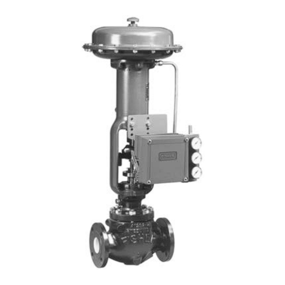
Figure 1. Typical Mounting for Fisher 3582 and 3582i Positioners and 3583 Transmitters
W5498-1
CONTROL VALVE WITH
3582 POSITIONER
www.Fisher.com
2
2
2
. . . . . . . . . . . . . . . .
6
6
7
7
. . . . . . . .
8
9
9
10
12
13
W8424
CONTROL VALVE WITH
3582i POSITIONER
. . . . . . . . . . . . . . . . . . . . . . . . . . . . . . . . . . . . . .
. . . . . . . . . . . . . . . . . . . . . . . . . .
. . . . . . . . . . . . . . . . . . . . . . . .
. . . . . . . . . . . . . . . . . . . . . . . . . . . . .
3582, 582i, and 3583
February 2015
. . . . . . . . . . . . . . . . . . . . . .
. . . . . . . . . . . . . . . . . . . . . . .
. . . . . . . . . . . . . . . . . . . . . .
. . . . . . . . . . . . . . . . . . . . . .
. . . . . . . . . . . . . . . . . .
. . . . . . . . . . . . . . . . . .
. . . . . . . . . . . . . . . . . . .
. . . . . . . . . . . . .
(continued on page 2)
W5499-1
CONTROL VALVE WITH
3583 TRANSMITTER
18
18
18
20
20
20
21
21
23
24
24
26
Advertisement
Table of Contents

Related Manuals for Fisher 3582


Summary of Contents for Fisher 3582
-
Page 1: Table Of Contents
....... . . Figure 1. Typical Mounting for Fisher 3582 and 3582i Positioners and 3583 Transmitters W5499‐1... -
Page 2: Introduction
Refer to separate instruction manuals for information on the control valve, actuator, and accessories. Do not install, operate or maintain a 3582 pneumatic valve positioner, a 3582i electro‐pneumatic valve positioner, or a 3583 pneumatic valve stem position transmitter without being fully trained and qualified in valve, actuator and accessory installation, operation and maintenance. - Page 3 Instruction Manual 3582, 582i, and 3583 D200138X012 February 2015 Table 1. Specifications for Fisher 3582 and 3582i Valve Positioners Note: Specifications for 3582 positioners include 3582i 3582A, 3582C, 3582D, 3582G, and 3582NS unless 1.4 bar (20 psig) Supply: 0.46 normal m otherwise indicated (17.2 scfh)
- Page 4 Instruction Manual 3582, 582i, and 3583 February 2015 D200138X012 Table 1. Specifications for Fisher 3582 and 3582i Valve Positioners (Continued) Operative Temperature Limits Hazardous Area Classification for 3582 Standard Construction 3582 valve positioners comply with the requirements 3582 and 3582i: -40 to +71_C (-40 to +160_F)
- Page 5 Instruction Manual 3582, 582i, and 3583 D200138X012 February 2015 Table 2. Specifications for Fisher 3583 Valve Stem Position Transmitters Input Signal Operating Influence 105 mm (4.125 inches) of valve stem travel; Output signal changes 1.67 percent per bar adjustable to obtain full output signal with lesser (0.23 percent per 2 psig) change in supply pressure...
-
Page 6: Type Number Descriptions
These can be supplied as 10CFR, Part 21 items. The 3582i is an electro‐pneumatic valve positioner, consisting of a 582i electro‐pneumatic converter installed on a 3582 pneumatic valve positioner. The 3582i valve positioner provides an accurate valve stem position that is proportional to a DC current input signal. -
Page 7: Educational Services
Instruction Manual 3582, 582i, and 3583 D200138X012 February 2015 Refer to the unit nameplate to determine the type of positioner or transmitter, supply pressure, etc. WARNING This product is intended for a specific current range, temperature range and other application specifications. Applying different current, temperature and other service conditions could result in malfunction of the product, property damage or personal injury. -
Page 8: Hazardous Area Classifications And Special
Typically, the positioner or transmitter is ordered with the actuator. If so, the factory mounts the valve positioner or valve stem position transmitter and connects the valve positioner output to the actuator. If a Fisher 67CFR filter‐regulator is specified, it may be integrally mounted to the valve positioner or valve stem position transmitter, except for the 3582NS positioner. -
Page 9: Csa
February 2015 Intrinsically Safe, Explosion proof, Type n, Dust‐Ignition proof, DIV 2 No special conditions for safe use. Refer to table 4 for additional information. Table 4. Hazardous Area Classifications for Fisher 582i Converter —CSA (Canada) Certification Certification Obtained Entity Rating... -
Page 10: Atex
Instruction Manual 3582, 582i, and 3583 February 2015 D200138X012 ATEX Standards Used for Certification EN 60079-0: 2012 EN 60079-31: 2009 EN 60079-1: 2007 EN 61241-0: 2006 EN 60079-11: 2012 EN 61241-1: 2004 EN 60079-15: 2010 EN 61241-11: 2006 Special Conditions for Safe Use Intrinsically Safe This equipment is intrinsically safe and can be used in potentially explosive atmospheres. - Page 11 Instruction Manual 3582, 582i, and 3583 D200138X012 February 2015 Table 6. Hazardous Area Classifications for Fisher 582i Converter —ATEX Certificate Certification Obtained Entity Rating Temperature Code II 1 G & D T4 (Tamb ≤ 71°C) Intrinsically Safe Ui = 30 VDC T5 (Tamb ≤...
-
Page 12: Iecex
Type n WARNING Disconnect power before opening. -40_C ≤ Ta ≤ +71_C; T6 (Ta ≤ +71_C) Refer to table 7 for approval information. Table 7. Hazardous Area Classifications for Fisher 582i Converter —IECEx Certificate Certification Obtained Entity Rating Temperature Code Ui = 30 VDC T4 (Tamb ≤... -
Page 13: Mounting
Key numbers used in this procedure are shown in figure 2 except where indicated. 1. Figure 2 shows the various mounting parts required for mounting on Fisher actuators. Mounting parts for actuators that require spacers have the spacers (key 50) included. 657 and 667 actuators, sizes 70 through 100, with or without a side‐mounted handwheel, use spacers (keys 97 and 102) between the stem connector and the connector... - Page 14 5. 4. Mount the 67CFR regulator: D 3582 valve positioners (except 3582NS) and 3583 valve stem position transmitters, mount the regulator on the integral boss on the bypass block. D 3582NS valve positioners, use the mounting plate with provision for separately mounting the 67CFR regulator.
- Page 15 If necessary, adjust the travel pin position so that the 30‐degree marks are the same distance from the respective case index mark at each end of actuator travel. Figure 3. Spacing for Mounting on Other than Fisher Actuators STEM TRAVEL 9.5 mm (0.375 Inch) Stem...
- Page 16 ARM (KEY 2) POSITIONER YOKE VALVE PLUG STEM CV1768-C A1397‐2 Figure 5. Mounting Plates Used with Fisher 3582 Valve Positioners and 3583 Valve Stem Position Transmitters SET NO. 1 SET NO. 2 SET NO. 3 SET NO. 4 HOLES FOR...
- Page 17 ARM AT MID‐TRAVEL POSITION ACTUATOR STEM TRAVEL INDEXES NOTES: ..MAXIMUM ROTATION FROM MID‐TRAVEL POSITION..ALIGN INDEX MARKS AS SHOWN FOR MID‐TRAVEL POSITION. 70CA0750‐C A2452‐2 Table 8. Fisher 3582 and 3583 Mounting Information MAXIMUM MAXIMUM MOUNTING HOLES MOUNTING ACTUATOR ACTUATOR TRAVEL PIN...
-
Page 18: Changing Cam Position
Instruction Manual 3582, 582i, and 3583 February 2015 D200138X012 Changing Cam Position Refer to figure 21 for a typical cam illustration and key number locations. Note For Valve Positioners: The small arrow on the cam must point in the direction of stem movement with increasing actuator diaphragm pressure. - Page 19 Instruction Manual 3582, 582i, and 3583 D200138X012 February 2015 Figure 7. Typical Dimensions and Connections 141.2 139.7 246.1 (5.56) (5.50) (9.69) 119.1 57.2 182.6 (4.69) (2.25) (7.19) OF ACTUATOR 12.7 (.31) (0.50) 1/2‐14 NPT CONDUIT CONN 8.6 (.34) ∅ HOLES SPACED 17.5 (.69)
-
Page 20: Output Connection
1/8‐inch stems are also included. Install the connectors on the 3582 block assembly or 582i housing as shown in figure 8. Before installing the connectors on the positioner, apply sealant to the threads. Sealant is provided with the diagnostic connections and hardware. -
Page 21: Vent
Instruction Manual 3582, 582i, and 3583 D200138X012 February 2015 Vent WARNING Personal injury or property damage could result from fire or explosion of accumulated gas if a flammable gas is used as the supply pressure medium and the positioner/actuator is in an enclosed area. The positioner/actuator assembly does not form a gas‐tight seal, and when the assembly is enclosed, a remote vent line, adequate ventilation, and necessary safety... - Page 22 FOR TROUBLESHOOTING OR MONITORING OPERATION, AN INDICATING DEVICE CAN BE A VOLTMETER ACROSS A 250 OHM RESISTOR OR A CURRENT METER. A3875 Figure 10. Input Equivalent Circuit for Fisher 582i Figure 11. Wiring Connections for Fisher 582i Converter Converter FIELD...
-
Page 23: Converter Installation
Note Before planning to retrofit an installed 3582 positioner, refer to the positioner mounting plate illustrations shown in figure 5. Mounting plates with a three‐hole mounting pattern (positioner to mounting plate) cannot support a 582i converter. Do not attempt to mount a 582i converter on an existing 3582 positioner which has a three‐hole mounting pattern. -
Page 24: Operating Information
Then, tighten the locking nut against the spring retainer bracket. Hook the spring into the spring retainer bracket. When shipped from the factory, 3582 valve positioners and the 3582i valve positioner have a linear cam, Cam A, installed in the operating position. Two characterized cams, Cams B and C, are available. These characterized cams may be used to modify the valve flow characteristics. - Page 25 Instruction Manual 3582, 582i, and 3583 D200138X012 February 2015 for example, the stem will travel 50 percent with cam A, 68 percent with cam B, and 32 percent with cam C. Figure 13 shows how the flow characteristics change when using the cams with a valve that has equal percentage characteristics.
-
Page 26: Valve Stem Position Transmitter Cam Information
Valve Positioner Bypass Operation 3582 and 3582D valve positioners, and 3582NS positioners with bypass, are supplied with a bypass assembly. A handle on the bypass assembly permits selecting positioner or bypass operation. Refer to figure 24 for key number locations. -
Page 27: Input Signal Ranges
To change to split‐range operation, perform the beam alignment procedures then perform the calibration procedure using the desired split range inputs that result in full valve travel. For example, for a 3582 positioner with a 0.2 to 1.0 bar (3 to 15 psig) input signal range in a two‐way split, a 0.6 bar (9 psig) input signal should completely stroke the valve for a 0.2 to 0.6 bar (3 to 9 psig) signal range. -
Page 28: Changing Valve Positioner Action
Note 3582 valve positioners require a relatively small percentage of the instrument pressure span to obtain full valve travel. With the travel pin set to equal the valve travel, the input signal change required to fully stroke the valve can be reduced to 33 percent of normal input signal change. -
Page 29: Calibration Of Valve Positioner Or Valve Stem Position Transmitter
Calibration Of Valve Positioner Or Valve Stem Position Transmitter The following beam alignment and calibration procedures are applicable for both 3582 and 3582i valve positioners and 3583 valve stem position transmitters. WARNING During calibration the valve may move. To avoid personal injury or property damage caused by the release of pressure or process fluid, provide some temporary means of control for the process. - Page 30 4. Connect the input to the valve positioner and set the input signal value at midrange. For example, for a 3582 valve positioner with a 0.2 to 1.0 bar (3 to 15 psig) input signal range, set the input signal at 0.6 bar (9 psig). Then apply supply pressure to the valve positioner.
-
Page 31: Calibration
3. Apply an input signal equal to the low value of the input signal range. For example, for a 3582 valve positioner with a 0.2 to 1.0 bar (3 to 15 psig) input signal range, set the input signal at 0.2 bar (3 psig). Loosen the nozzle locknut and adjust the nozzle until the actuator moves to the proper end of its travel. -
Page 32: Principle Of Operation
Principle of Operation 3582 Valve Positioners The 3582 (3582, 3582NS and 3582A, C, D, and G pneumatic valve positioners) accepts a pneumatic input signal from a control device. Figure 17 is an operational schematic for a direct‐acting pneumatic valve positioner. -
Page 33: 3582I Valve Positioner
Instruction Manual 3582, 582i, and 3583 D200138X012 February 2015 Figure 17. Schematic Illustration of Fisher 3582 Positioner OUTPUT TO ACTUATOR RELAY INSTRUMENT INPUT BELLOWS SUPPLY FEEDBACK AXIS PIVOT NOZZLE FLAPPER ASSEMBLY ROTARY SHAFT ARM DIRECT ACTING QUADRANT TRAVEL PIN INPUT AXIS... -
Page 34: 3583 Valve Stem Position Transmitters
Supply pressure is connected to the 83L relay. A fixed restriction in the relay limits flow to the nozzle so that when the flapper is not restricting the nozzle, air can bleed out faster than it is being supplied. Figure 19. Schematic Illustration of Fisher 3583 Transmitter OUTPUT TO STEM... -
Page 35: Maintenance
Instruction Manual 3582, 582i, and 3583 D200138X012 February 2015 the beam to pivot about the feedback axis and moving the flapper closer to the nozzle until equilibrium is reached. The position transmitter output pressure is again proportional to the valve stem position. -
Page 36: Changing The Range Spring
Unless otherwise noted, key numbers used in this procedure are shown in figures 24 and 25. A gasket (key 34C) is located behind the bypass handle (key 34D) of 3582 valve positioners or the manifold (key 34D) of 3583 valve stem position transmitters. -
Page 37: Replacing The Nozzle O-Ring
4. Set the new gasket in place on the four locating pins and replace the bypass handle or manifold. The case gasket (key 104) is located between the case (key 1 in figure 21) and the bypass block (key 34A) in a 3582 valve positioner or a 3583 valve stem position transmitter or the housing of the 582i converter (key 1 in figure 26). -
Page 38: Adjusting The Flapper Pivot
Instruction Manual 3582, 582i, and 3583 February 2015 D200138X012 1. For valve positioners using a bypass, direct action, and a full‐range input signal, place the positioner in bypass operation by moving the bypass handle to BYPASS. Then, shut off the supply pressure. For all other valve positioners and valve stem position transmitters, isolate the control valve from the system and shut off all pressure lines. -
Page 39: Reassembling The 582I Converter
Instruction Manual 3582, 582i, and 3583 D200138X012 February 2015 Note To check the operation of the I/P module, remove the pipe plug (key 12), and connect a pressure gauge. Provide a 1.4 bar (20 psig) supply pressure to the converter. With a 4 mA signal the pressure output should read 0.16 to 0.24 bar (2.3 to 3.5 psig). With a 20 mA input signal the pressure output should read 0.96 to 1.07 bar (14.0 to 15.5 psig). -
Page 40: Parts Ordering
Use only genuine Fisher replacement parts. Components that are not supplied by Emerson Process Management should not, under any circumstances, be used in any Fisher instrument. Use of components not supplied by Emerson Process Management may void your warranty, might adversely affect the performance of the instrument, and could cause personal injury or property damage. -
Page 41: Parts List
Nozzle, SST 3582 3583 Note Flapper Sub‐Assembly Parts in the following list are common to both 3582 valve positioners and 3583 position transmitters, unless identified by specific type number. Note Parts 19A through 19L are shown in figure 20. Note Part numbers are shown for recommended spares only. - Page 42 Instruction Manual 3582, 582i, and 3583 February 2015 D200138X012 Figure 21. Fisher 3582 and 3583 Positioners and Transmitters Assembly Drawing SECTION B‐B TYPICAL CAM (KEY 4) SECTION A‐A NOTE: APPLY A GOOD‐QUALITY THREAD LOCKING COMPOUND TO THE THREAD OF THE NOZZLE ADAPTOR (KEY 3).
- Page 43 46* Instrument Gauge, Dual Scale Pipe Plug, pl steel 0-30 psig/0-2 kg/cm Req'd when gauges or test connections are not used: (3-15 psig/0.2-1.0 kg/cm2 ranges) 11B4040X042 3 req'd for 3582 positioners 0-60 psig/0-4 kg/cm Plated carbon steel (6-30 psig/0.4-2.0 kg/cm2 ranges) 11B4040X052 316 SST...
- Page 44 Instruction Manual 3582, 582i, and 3583 D200138X012 February 2015 Description Part Number Description Part Number Test Connection 3582C, 3582D (3 req'd) 3583C (2 req'd) Adhesive, Loctite Retaining Compound 3582NS (3 req'd) (not furnished with positioner) Locking Nut, aluminum 103* O‐Ring, nitrile, (not shown) used with integrally Locking Sleeve, aluminum mounted 67CFR filter regulator...
- Page 45 34F Washer, polyethylene Block Assembly 34G Screw, pl steel 3582, 3582D 34K Spring Seat, SST 3582NS Spring Retainer, pl steel Figure 24. Fisher 3582 Block Assembly with Bypass 21B8560‐B 21B8562‐B 3582 3582D AND 3582NS TYPICAL SECTION AA NOTE: SECTIONAL OF 3582...
- Page 46 Hi‐temp. const. 34G Cap Screw, pl steel 3582A, 3582C 3583C 106 Pipe Plug, pl steel 3582NS For 3583 & 3583C (2 req'd) Figure 25. Fisher 3582 and 3583 Block Assemblies without Bypass 21B8565‐B 21B8564‐B 21B8567‐B 3582G 3582C AND 3582NS 3583...
- Page 47 Instruction Manual 3582, 582i, and 3583 D200138X012 February 2015 Description Part Number Description Part Number 582i (figure 26) 14* Supply Gauge, Dual Scale 0-30 psig/0-2 kg/cm 11B4040X042 I/P Module 0-60 psig/0-4 kg/cm 11B4040X052 Housing 14* Supply Gauge, Triple Scale 1/2‐14 NPT conduit connection 0-30 psig/0-0.2 MPa/0-2 bar...
- Page 48 D200138X012 Mounting Parts Description Washer, pl steel 657 For Mounting 3582, 3582i, or 3583 Only w/o side‐mtd. h'wheel (continued) Size 70 (2 req'd) (figure 2) up to 76 mm (3 inch) travel 78 to 102 mm (3.0625 to 4 inch) travel Sizes 80 &...
- Page 49 Instruction Manual 3582, 582i, and 3583 D200138X012 February 2015 Description Description Part Number Spacer, steel Hex Nut 657 (continued) 657NS or 667NS w/side‐mtd. h'wheel Size 80 (none req'd) Sizes 34, 50, & 60 (2 req'd) All other types and sizes (2 req'd) Size 40 (none req'd)
- Page 50 Instruction Manual 3582, 582i, and 3583 February 2015 D200138X012 Description Description Spacer, steel Cap Screw, pl steel (2 req'd) 657 or 667 w/ side‐mtd. h'wheel 657 w/side‐mtd. h'wheel (continued) Size 70 & 87 Size 100 up to 51 mm (2 inch) travel (2 req'd) 52 to 76 mm (2.0625 to 3 inch) travel (2 req'd)
- Page 51 For separately mounted 67CFR The following parts (key numbers 48 through 102) are used when mounting both a 3582 positioner and a 3583 transmitter on a 657 or Cap Screw, pl steel, all sizes (8 req'd) 667 actuator without a side‐mounted handwheel.
- Page 52 Instruction Manual 3582, 582i, and 3583 February 2015 D200138X012 Description Description Cap Screw, pl steel Cap Screw, pl steel (4 req'd) (continued) 657 657 or 667 w/side‐mtd. h'wheel (continued) Sizes 30 thru 60, & 80 Size 87 Size 100 up to 76 mm (3 inch) travel (none req'd) up to 64 mm (25 inch) travel...
- Page 53 The following parts (key numbers 48 through 87) are used when Hex Nut, pl steel, for 667 only (2 req'd) mounting both a 3582 positioner and a 3583 transmitter on a 657 or Lockwasher, pl steel 667 Size 45 actuator with side‐mounted handwheel.
-
Page 54: Loop Schematics
This section includes loop schematics required for wiring of intrinsically safe installations. If you have any questions, contact your Emerson Process Management sales office. Figure 28. CSA Loop Schematic for Fisher 582i Converter (Installation drawing GE28591) NOTES: 1. BARRIERS MUST BE CSA CERTIFIED WITH ENTITY PARAMETERS AND ARE TO BE INSTALLED IN ACCORDANCE WITH THE... - Page 55 3582, 582i, and 3583 D200138X012 February 2015 Figure 29. FM Loop Schematic for Fisher 582i Converter (Installation drawing GE28590) WARNING FOR INTRINSICALLY SAFE APPLICATIONS: THE APPARATUS ENCLOSURE CONTAINS ALUMINUM AND IS CONSIDERED TO CONSTITUTE A POTENTIAL RISK OF IGNTION BY IMPACT AND FRICTION.
- Page 56 Responsibility for proper selection, use, and maintenance of any product remains solely with the purchaser and end user. Fisher and FlowScanner are marks owned by one of the companies in the Emerson Process Management business unit of Emerson Electric Co. Emerson Process Management, Emerson, and the Emerson logo are trademarks and service marks of Emerson Electric Co.
Need help?
Do you have a question about the 3582 and is the answer not in the manual?
Questions and answers