Table of Contents
Advertisement
Instruction Manual
Form 5054
June 1998
3582 Series Valve Positioners, Type 3582i Valve
Positioner, and 3583 Series Valve Stem Position
Transmitters
Contents
. . . . . . . . . . . . . . . . . . . . . . . . . . . . . .
. . . . . . . . . . . . . . . . . . . . . . . . . . . . .
. . . . . . . . . . . . . . . . . . . . . . . . . . . . . . . . . .
. . . . . . . . . . . . . . . . . . . . . . . . . . . . . . .
. . . . . . . . . . . . . . . . . . . . . . . . . . . . . . . .
. . . . . . . . . . . . . . . . . . . . . . . . . . . . . . . . . . . .
. . . . . . . . . . . . . . . . . . . . . . . .
. . . . . . . . . . . . . . . . . . . . . . . .
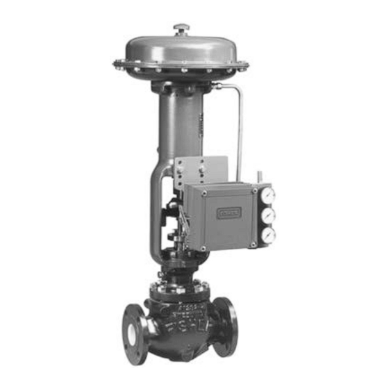
W5498/IL
Figure 1. Typical Mounting for the 3582 Series, Type 3582i, and 3583 Series Positioners and Transmitters
. . . . . . . . . . . . . . . . . . .
. . . . . . . . . . . . . . . . . . . . . . .
. . . . . . . . . . . . . . . . . . . . . . . .
. . . . . . . . . . . . . . . . . . . . .
W5500/IL
3582 and 3583 Series
. . . . . . . . . . . . . . . . . . . . . . . . . . . . . . . . . . . . . .
2
2
2
2
4
5
. . . . . . . . . . . . . . . . . . . . . . . . . . . . .
6
9
9
10
11
11
. . . . . . . . . . . . . . . . . . . . . . . . . . . . . . . . . .
. . . . . . . . . . . . . . . . . . . .
. . . . . . . . . . . . . . . . . . . . . . . . .
. . . . . . . . . . .
. . . . . . . . . . . . . . . . . .
. . . . . . . . . . . .
. . . . . . . . . . .
. . . . . . . . . . . . . . . . . . . . . . . .
. . . . . . .
. . . . . . . . . . . .
W5499/IL
11
12
12
13
14
14
15
15
16
16
17
17
Advertisement
Table of Contents

Related Manuals for Fisher 3582


Summary of Contents for Fisher 3582
-
Page 1: Table Of Contents
........W5498/IL W5500/IL W5499/IL Figure 1. Typical Mounting for the 3582 Series, Type 3582i, and 3583 Series Positioners and Transmitters... -
Page 2: Introduction
Type 582i electro-pneumatic con- tion for the 3582 Series pneumatic valve positioners, verter installed on a Type 3582 pneumatic valve posi- the Type 3582i electro-pneumatic valve positioner, tioner. The Type 3582i valve positioner provides an... - Page 3 3582 and 3583 Series Table 1. Specifications for 3582 Series and Type 3582i Valve Positioners Input Signal /hr) 35 Psig (2.4 bar) Supply: 285.5 scfh (8.1 normal 3582 Series: /hr) 3 to 15 psig (0.2 to 1.0 bar), 6 to 30 psig (0.4 to 2.0 bar), or...
-
Page 4: Specifications
3582 and 3583 Series Table 1. Specifications for 3582 Series and Type 3582i Valve Positioners (Continued) Pressure Gauges Maximum Valve Stem Travel 1-1/2 inch (40 mm) diameter with plastic case and 4-1/8 inches (105 mm); adjustable to obtain lesser brass connection... -
Page 5: Installation
3582 and 3583 Series Table 2. Specifications for 3583 Series Valve Stem Position Transmitters Input Signal Reference Accuracy 4-1/8 inches (105 mm) of valve stem travel; adjust- 1 percent of output signal span able to obtain full output signal with lesser stem... -
Page 6: Mounting
1. Figure 3 shows the various mounting parts required 2. As shown in figures 3 and 4, attach the connector for mounting on Fisher actuators. Mounting parts for arm (key 48) to the stem connector so that the con- Fisher actuators that require spacers have the spacers nector arm extends through the yoke legs on the side (key 50) included. - Page 7 3582 and 3583 Series Table 3. 3582 and 3583 Series Mounting Information MOUNTING MAXIMUM MAXIMUM MOUNTING HOLES ACTUATOR ACTUATOR TRAVEL PIN ACTUATOR ACTUATOR TRAVEL PIN TRAVEL TRAVEL HOLES SET NO. TYPE TYPE SIZE SIZE POSITION POSITION TYPE TYPE SIZE SIZE...
- Page 8 HOLES FOR MOUNTING POSITIONER TO PLATE BF2635-B/DOC Figure 5. Mounting Plates Used with 3582 Series Valve Positioners and 3583 Series Valve Stem Position Transmitters 6. Position the actuator to its mid-travel position using 11. Check the travel pin setting using the following a handwheel or manual loading regulator.
-
Page 9: Changing Cam Position
6.50 Millimeters 29 or less 30 MAX. 11B6520-C/DOC Figure 6. Spacing for Mounting on Other Than Fisher Actuators Changing Cam Position Refer to figure 21 for a typical cam illustration and key number locations. Note For Valve Positioners: The small... -
Page 10: Supply Connection
3582 and 3583 Series 9.88 5.50 5.56 .34 (8.6) HOLES (251.0) (139.7) (141.2) SPACED .69 (17.5) APART 2.25 4.69 (51.1) (119.1) 7.19 (182.6) (7.9) (12.7) 11.44 (290.6) 5.56 .34 (8.6) HOLES 5.50 (141.2) SPACED .69 (17.5) APART (139.7) 10.50 5.00 2.25... -
Page 11: Output Connection
If mounting the valve positioner in the field, Install the connectors on the 3582 block assembly or connect 3/8-inch tubing between the 1/4-inch NPT Type 582i housing as shown in figure 9. Before instal-... -
Page 12: Vent
3582 and 3583 Series Vent WARNING If a flammable, toxic, or reactive gas is to be used as the supply pressure me- dium, personal injury or property dam- age could result from fire or explosion of accumulated gas or from contact with toxic, or reactive gas. -
Page 13: Installation Of Type 582I Converter
3. Please contact your Fisher sales office or representative before planning to up- grade any existing 3582 Series valve positioner by field installation of a Type 582i electro-pneumatic converter. Also, refer to this section of the instruction manual... -
Page 14: Operating Information
12. Return the control valve package to service. When shipped from the factory, 3582 Series valve po- sitioners and the Type 3582i valve positioner have a linear cam, Cam A, installed in the operating position. -
Page 15: Valve Stem Position Transmitter Cam Information
Figure 14. Flow Characteristics with Different Cams and Equal Percentage Valve Plug Valve Positioner Bypass Operation Type 3582 and 3582D valve positioners, and Type 3582NS positioners with bypass, are supplied with a bypass assembly. A handle on the bypass assembly permits selecting positioner or bypass operation. -
Page 16: Input Signal Ranges
For example, for a 3582 Series po- Input Signal Ranges sitioner with a 3 to 15 psig (0.2 to 1.0 bar) input signal... -
Page 17: Changing Valve Positioner Action
Calibration Of Valve Positioner Or Changing Valve Positioner Action Valve Stem Position Transmitter Converting a 3582 Series valve positioner or Type 3582i valve positioner from direct acting (an increasing input signal, either pneumatic or electrical, increases Note... - Page 18 For example, for a adjustment. Continue this process until 3582 Series valve positioner with a 3 to 15 psig (0.2 to the required arm position can be at- 1.0 bar) input signal range, set the input signal at 9 tained.
-
Page 19: Calibration
3582 Series Valve Positioners nozzle squarely. If it does not, adjust the nozzle and The 3582 Series (the Type 3582, 3582NS and Types re-level the beam. After alignment, the valve positioner 3582A, C, D, and G pneumatic valve positioners) ac- is ready for calibration. -
Page 20: Type 3582I Valve Positioner
Figure 19. Schematic Illustration of Type 3582i Positioner 22A7965-A A2453-2*/IL 3583 Series Valve Stem Position Figure 18. Schematic Illustration of 3582 Series Positioner Transmitters 3583 Series (Type 3583, 3583C) pneumatic valve stem position transmitters are mechanically linked to When the input signal decreases, the bellows con-... -
Page 21: Maintenance
3582 and 3583 Series cannot suddenly open or close the valve. OUTPUT TO STEM Use bypass valves or completely POSITION INDICATOR OR RECORDER shut off the process to isolate the valve from process pressure. Relieve process RELAY pressure on both sides of the valve. -
Page 22: Changing The Range Spring
(key 1 in figure 21) and the bypass block (key is stamped on the nameplate. 34A) in a 3582 Series valve positioner or a 3583 Se- ries valve stem position transmitter or the housing of Perform the following procedure to change the range the Type 582i converter (key 1 in figure 27). -
Page 23: Removing And Replacing The Relay
3582 and 3583 Series 6. Reinstall the nozzle onto the nozzle adapter, leav- Obtain the relay repair kit listed in the parts kits. This ing the locking nut loose. kit provides the parts required to repair the relay as- sembly. -
Page 24: Adjusting The Flapper Pivot
15. Install the relay assembly on the positioner case. Fisher sales representative or sales of- fice for repair. 16. Apply supply pressure to the positioner case and check the relay assembly for leaks with soap solution. -
Page 25: Reassembling The Type 582I Converter
Note signal values may damage the converter module. Parts in the following list are common to both the 3582 Series valve positioners and the 3583 Series position 7. Apply a 20 milliampere dc current input signal to transmitters, unless identified by specific type or se- the converter. - Page 26 Type 3582NS 13A1451 X022 item. Note Description Part Number Parts 19A through 19L are shown in figure 23. For 3582 Series pneumatic valve positioners For units w/gauges 19A Adjustment Arm, pl steel 2V6066 25182 SST fittings 12B8045 X012 19B Flapper, SST...
- Page 27 3582 and 3583 Series NOTE: APPLY A GOOD-QUALITY THREAD LOCKING COMPOUND TO THE THREAD OF THE NOZZLE ADAPTOR (KEY 3). 41B8558-E/DOC Figure 21. 3582 and 3583 Series Positioners and Transmitters Assembly Drawing...
- Page 28 3582 and 3583 Series ASSEMBLE WITH LETTER T ON THIS SURFACE 12A7441-C / DOC Figure 22. Nozzle Sub-Assembly 13A1451-E/DOC Description Part Number Supply Gauge, Dual Scale Figure 23. Flapper Sub-Assembly (Key 19) Types 3582, 3582G, 3583 0–30 psig/0–2 kg/cm 11B4040 X042 0–60 psig/0–4 kg/cm...
- Page 29 3582 and 3583 Series 21B8560-B/DOC 21B8562-B/DOC Figure 24. 3582 Series Block Assembly with Bypass 21B8565-B/DOC 21B8564-B/DOC 21B8567-B/DOC 21B8563-B/DOC 21B8566-B/DOC NOTE: PIPE PLUG (KEY 106) ON 3583 AND 3583C ONLY. Figure 25. 3582 and 3583 Series Block Assemblies without Bypass...
- Page 30 Type 3582NS, EPDM 17B4780 X012 Hi-temp. const. 1U9018 X0072 34D Manifold For Type 3582NS, aluminum/SST/EPDM – – – 3582 Series, std. and hi-temp. const. 1V9429 08012 Diaphragm 3583 Series, std. and hi-temp. const. 10A0746 X012 Std. const., nitrile/nylon 1V5578 02032...
- Page 31 3582 and 3583 Series Description Part Number O-Ring Std. const., nitrile 1D1346 06992 Hi-temp. const., fluoroelastomer 1D2899 X0022 For Type 3582NS, EPDM Duro 80A – – – O-Ring (3 req’d) Std. const., nitrile 1D6875 06992 Hi-temp. const., fluoroelastomer 1N4304 06382...
- Page 32 Mounting Parts Size 34 thru 60 (none req’d) – – – Size 70 (2 req’d) For Mounting 3582, 3582i, or 3583 Only up to 3-inch (76 mm) travel 1K8995 25072 3-1/16 to 4-inch (78 to 102 mm) travel 1H7231 25072 (figure 3) Sizes 80 &...
- Page 33 3582 and 3583 Series Description Part Number Description Part Number Washer, pl steel (cont’d) Spacer, steel (cont’d) Size 100 (2 req’d) 1H7231 25072 3-1/16 to 4-inch (78 to 102 mm) travel Type 657NS or 667NS (2 req’d) 1R8019 24092 Size 40 (2 req’d)
- Page 34 3582 and 3583 Series Description Part Number Description Part Number Mounting Plate, steel (cont’d) Cap Screw, pl steel (cont’d) Type 1250 & 1250R 39A7852 X012 Size 70 All other types up to 3-inch (76 mm) travel (none req’d) – – –...
- Page 35 3582 and 3583 Series Description Part Number Description Part Number Cap Screw, pl steel (2 req’d) (cont’d) Mounting Bracket (cont’d) Size 100 Size 80 35A8821 X012 up to 2-1/2 inch (64 mm) travel 1A3525 24052 All other types (none req’d) –...
- Page 36 The following parts (key numbers 48 through 102) 2-1/16 to 3-inch (52 to 76 mm) travel 1A3525 24052 are used when mounting both a 3582 Series posi- 3-1/16 to 4-inch (77 to 102 mm) travel 1D7704 24052 tioner and a 3583 Series transmitter on a Type 657...
- Page 37 1R6839 99012 The following parts (key numbers 48 through 87) Cap Screw, pl steel, for Type 667 only are used when mounting both a 3582 Series posi- (5 req’d) 1A5534 24052 tioner and a 3583 Series transmitter on a Type 657 Spacer, pl steel for Type 667 only (5 req’d)
- Page 38 3582 and 3583 Series This section includes loop schematics required for wiring tions, contact your Fisher Controls sales representative of intrinsically safe installations. If you have any ques- or sales office. CSA Loop Schematic 21B5606-B Sheet 1 of 2 / DOC...
- Page 39 3582 and 3583 Series FM Loop Schematic 21B5607-D / DOC...
- Page 40 3582 and 3583 Series FlowScanner, Fisher, Fisher-Rosemount, and Managing The Process Better are marks owned by Fisher Controls International, Inc. or Fisher-Rosemount Systems, Inc. All other marks are the property of their respective owners. Fisher Controls International, Inc. 1989, 1998; All Rights Reserved...
Need help?
Do you have a question about the 3582 and is the answer not in the manual?
Questions and answers