Table of Contents
Advertisement
Quick Links
Specifications Information and Repair Parts Manual
Please read and save this Repair Parts Manual. Read this manual and the General Operating Instructions carefully before attempting to assemble, install, operate
or maintain the product described. Protect yourself and others by observing all safety information. The Safety Instructions are contained in the General Operating
Instructions. Failure to comply with the safety instructions accompanying this product could result in personal injury and/or property damage! Retain instructions
for future reference. AMT reserves the right to discontinue any model or change specifications at any time without incurring any obligation.
©2017 AMT Pump Company, A Subsidiary of The Gorman-Rupp Company, All Rights Reserved.
Periodic maintenance and inspection is required on all pumps to ensure proper operation. Unit must be clear of debris and sediment. Inspect for leaks and loose bolts. Failure to do so
voids warranty.
25FP Fire Pump Series
Refer to form 1808-633-00 for General Operating and Safety Instructions.
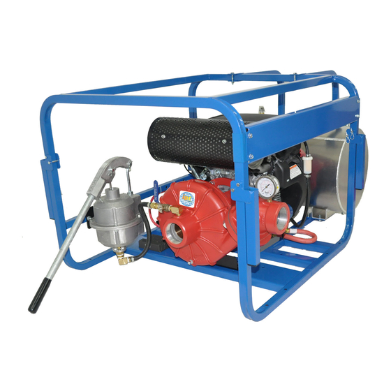
DESCRIPTION
This is a single-stage centrifugal pump designed for agriculture or fire fighting service. It is close coupled to an internal combustion air cooled engine and protected
by a roll frame equipped with four carry handles. The pump is compact and light-weight, designed for portability. Pump construction is rugged and allows for easy
maintenance.
Units are designed to handle clean water or water containing small (1/16" maximum spherical diameter) solids. Suction and discharge ports are 2-1/2" NPT
threaded. Discharge includes a built in bronze check valve to allow use of an exhaust or hand operated priming system.
Liquid temperature range is 40°F to 180° F (4°C to 82°C). Maximum casing pressure is 180 psi (1240 kPa). For use with nonflammable liquids that are chemically
compatible with pump component materials.
SPECIFICATIONS
Suction inlet.........................................................................2-1/2" NPT Female
Discharge outlet...................................................................2-1/2" NPT Female
Dimensions overall (Length x Width x Height)
25FP13AR & 25FP13HR..........................................................(32" x 32" x 25")
25FP23AR................................................................................(41" x 32" x 25")
Engine and fuel tank size
25FP13AR........................................................................B&S Vanguard 13HP
25FP13HR..................................................................................Honda GX390
25FP23AR........................................................................B&S Vanguard 23HP
25FP13ZR.........................................................................................Hatz 1B50
25FP10YR....................................................................................Yanmar L100
BASIC CONSTRUCTION
Pump is constructed of cast aluminum. Engine shaft is sealed with a self-
lubricating mechanical seal that consists of a silicon carbide stationary ring,
carbon rotating head, stainless steel spring and Viton® elastomer. Discharge
flange gasket and casing o-ring are Viton®.
UNPACKING
Refer to repair parts illustration and parts list to aid in identifying pump
components. Unpack and separate all pump components from shipping/
packaging materials, making sure all parts are accounted for. Retain all
manuals for future reference.
Package should contain:
•
Pump/engine completely assembled and mounted in roll frame.
•
Rubber feet with fasteners bag.
•
Frame handle parts bag.
•
Frame panel and parts bag.
•
Engine owner's manual
•
Pump general safety manual,
•
Specifications information and repair parts manual.
25FP-250-00
ASSEMBLY
Roll Frame Handle Assembly:
1.
Install pivot bearing (A6) in frame hole. Ends of bearing must be flush
with outside of frame rail.
2.
Hold handle (A3) perpendicular to frame tube.
3.
Slide handle end ears over frame tube until handle tube end contacts
frame.
4.
Align handle ear hole with bearing in frame.
5.
Install pivot pin (A5) and pin end cotter (A7).
6.
Install lock pin (A4) in other handle ear hole. Secure with cotter (A7).
7.
Handle can be locked in the up or down position with lock pin.
8.
Repeat procedure for [3] three remaining handles.
Roll Frame Panel Assembly:
1.
Slide panel mounting brackets (A10) over frame tube where panel will
be positioned.
2.
Align slots in end of panel (A9) with holes in mounting brackets.
3.
Fasten panel to brackets with bolts (A11) and nuts (A12) provided.
Rubber Feet Assembly:
1.
Install bolt (A20) through rubber foot (A19) center hole.
2.
Slide bolt through hole provided in lower tube of roll frame.
3.
Fix in position with nut (A21).
4.
Repeat for [3] three remaining feet.
Battery Tray Assembly:
1.
Locate battery tray (A14) on frame rail.
2.
Install mounting bolts (A15) with washers (A16), and nuts (A17).
3.
Install "J" bolts in tray slots.
4.
Install hold down angle on "J" bolt threaded ends, fix with wing nuts.
Install Battery:
1.
Maximum battery size is 5-1/4" wide X 7-3/4" long, 230 CCA (Cold
Cranking Amps) or greater U1/U1R Lawn and Garden battery.
2.
Position battery in tray with (+) terminal towards engine end of frame
and (-) battery terminal towards pump end of frame.
3.
Hold battery in position with hold down angle, "J" bolts, and wing nuts.
4.
Connect engine starter red cable to battery (+) terminal and ground
black cable to (-) terminal with fasteners (not provided).
1
25FP Series
10/2017
Advertisement
Table of Contents

Related Manuals for AMT 25FP13AR


Summary of Contents for AMT 25FP13AR
-
Page 1: Specifications
Instructions. Failure to comply with the safety instructions accompanying this product could result in personal injury and/or property damage! Retain instructions for future reference. AMT reserves the right to discontinue any model or change specifications at any time without incurring any obligation. -
Page 2: Installation
25FP Series Specifications Information and Repair Parts Manual 25FP Fire Pump Series Fuel Tank Frame Assembly: [25FP23AR] Mounting Position fuel tank frame (A32) on roll frame. Locate the pump in an accessible area as close as practical to the liquid being Align holes in tank frame ears with holes in roll frame tubes and cross pumped. -
Page 3: Operation
25FP Series Specifications Information and Repair Parts Manual 25FP Fire Pump Series Connections to Pump • Remove priming pump handle from bracket and install in priming pump. Since even a slight leak will affect priming, head and capacity, especially when •... -
Page 4: Maintenance
25FP Series Specifications Information and Repair Parts Manual 25FP Fire Pump Series MAINTENANCE Before attempting to service the pump: • Familiarize yourself with this manual. • Shut down the engine and remove the spark plug wires to ensure that the Preventative Maintenance pump will remain inoperative. -
Page 5: Pump Reassembly
To remove the valve body unthread from muffler outlet [25FP23] or loosen For pumps equipped with a balancing ring [25FP23AR], check for free rotation clamp (C11) [25FP13AR] and slide connecting nipple (C10) off of muffler of impeller. Make sure there is no binding against balancing ring. A slight rub outlet. - Page 6 AMT Pump Company (AMT). Any part deemed to be defective by AMT will be replaced at no charge and shipped directly to the end user or distributor for replacement. AMT may require the end user to first return the part in question for inspectionbefore replacement parts are shipped.
- Page 7 25FP Series Specifications Information and Repair Parts Manual 25FP Fire Pump Series For Repair Parts contact dealer where pump was purchased. Please provide following information: -Model Number -Serial Number (if any) Part description and number as shown in parts list Figure A - Complete Unit 25FP23AR Figure A - Complete Unit 25FP13HR ONLY 25FP-250-00...
- Page 8 25FP Series Specifications Information and Repair Parts Manual Repair Parts List - Complete Unit (Reference Figure A) Part Number of Model Description 25FP23AR 25FP13AR 25FP13HR 25FP13ZR 25FP10YR Roll Frame C404-100-00 C404-100-00 C404-100-00 C404-100-00 C404-100-00 Handle Kit C404-120-90 C404-120-90 C404-120-90 C404-120-90 C404-120-90 (includes Ref.
- Page 9 25FP Series Specifications Information and Repair Parts Manual 25FP Fire Pump Series For Repair Parts contact dealer where pump was purchased. Please provide following information: -Model Number -Serial Number (if any) Part description and number as shown in parts list Figure B - Pump/Engine 25FP-250-00 10/2017...
- Page 10 Intermediate/Adapter Kit 25FP-031-96 25FP-030-96 25FP-030-96 25FP-033-96 25FP-032-96 (includes Ref. Nos. B3 to B6 – 25FP23AR) (includes Ref. Nos. B3 to B5 – 25FP13AR & 25FP23AR) Intermediate/Adapter Incl. w/B2 Incl. w/B2 Incl. w/B2 Incl. w/B2 Incl. w/B2 Stud (NO LONGER USED) Incl.
- Page 11 25FP Series Specifications Information and Repair Parts Manual 25FP Fire Pump Series For Repair Parts contact dealer where pump was purchased. Please provide following information: -Model Number -Serial Number (if any) Part description and number as shown in parts list Figure C - Hand &...
- Page 12 25FP Series Specifications Information and Repair Parts Manual Repair Parts List – Hand & Exhaust Primer (Reference Figure C) Part Number of Model Description 25FP23AR 25FP13AR 25FP13HR 25FP13ZR 25FP10YR Exhaust Primer Assembly 25FP-401-90 25FP-400-90 (includes Ref. Nos. C2 to C11) Valve Body Incl.
- Page 13 25FP Series Specifications Information and Repair Parts Manual 25FP Fire Pump Series For Repair Parts contact dealer where pump was purchased. Please provide following information: -Model Number -Serial Number (if any) Part description and number as shown in parts list Figure D - Fuel Tank 25FP-250-00 10/2017...
- Page 14 25FP Series Specifications Information and Repair Parts Manual Repair Parts List – Fuel Tank (Reference Figure D) Part Number of Model Description 25FP23AR 25FP13AR 25FP13HR 25FP13ZR 25FP10YR Fuel Tank C404-170-00 Fuel Cap Kit C404-172-90 Tank Mount Hardware Kit C404-171-90 (includes Ref. Nos. D4 & D5) Bolt 5/16-18 x ¾”...
- Page 16 www.amtpump.com...
Need help?
Do you have a question about the 25FP13AR and is the answer not in the manual?
Questions and answers