Advertisement
Quick Links
Specifications Information
Operating Instructions & Parts Manual
and Repair Parts Manual
Please read and save this Repair Parts Manual. Read this manual and the General Operating Instructions carefully before attempting to
assemble, install, operate or maintain the product described. Protect yourself and others by observing all safety information. The Safety
Instructions are contained in the General Operating Instructions. Failure to comply with the safety instructions accompanying this product
could result in personal injury and/or property damage! Retain instructions for future reference.
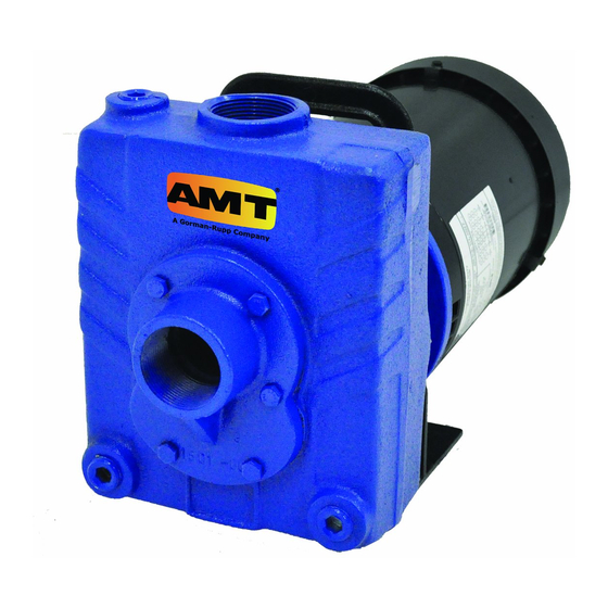
Self-Priming Centrifugal Pumps
High Volume Dewatering
Stainless Steel Models
Refer to form 1808-634-00 for General Operating and Safety Instructions.
Description
These centrifugal pumps are self-priming (to 20 ft. lift) units designed for high
volume liquid transfer - irrigation, de-watering, lawn sprinkling, etc. They can also
accommodate semi-solids (up to 3/8" dia.), sediment laden liquids, and liquids
with entrained air or gases. Units are constructed of 316 stainless steel and include
Viton elstomers. They are direct coupled to NEMA 56J frame, 3450 RPM motors
which require field wiring, no controls are supplied. Each pump is equipped with
a flapper valve to shorten re-prime time. Handles liquids from 40º to 200º F (4º to
93º C). For use with non-flammable, non-abrasive liquids compatible with pump
component materials.
Maintenance
Make certain
that unit is
disconnected from power source before
attempting to service or remove any
component!
NOTE: The pump casing should be
removed and inspected periodically to
insure that any foreign material is not
clogging internal pump parts. This unit
is equipped with a dual volute pump
casing. One of the volutes runs 180°, all
the way from the side opposite the
discharge into the discharge through a
completely enclosed passageway. If
foreign material clogs this area, it can
be dislodged by using a wire or long
spring.
MECHANICAL SEAL REPLACEMENT
Refer to Figure 1
Performance
Model
2827, 282J, 282D, 282F
2825, 2826, 282C, 282K
2821, 2822, 282A, 282B
2828, 282L, 282E, 282M
2762, 2764, 276B, 276D
2761, 2763, 276A, 276C
2767, 2766
(*) Shut-off; To convert to psi, multiply by SG (specific gravity of liquid), then dived by 2.31.
2761-255-00
IMPORTANT: Always replace both seal
seat (Ref. No. 8) and seal head (Ref. No.
9) to ensure proper mating of
components!
1. Unthread fasteners (Ref. No. 6) and
remove casing (Ref. No. 14) and
casing seal (Ref. No. 7) from adapter
(Ref. No. 5).
2. Unscrew impeller fastener (Ref. No.
13), and impeller (Ref. No. 11)
separately by turning each
counterclockwise.
NOTE: Most motors use an open end
7/16" wrench across flats on rear of
motor shaft (remove bearing cap for
access) to prevent shaft from turning.
Other motor shafts have a screwdriver
slot instead of flats.
3. Unscrew fasteners (Ref. Nos. 4 & 18)
and remove adapter, foot (Ref. No.
GPM of Water at Total Head in Feet
10'
20'
30'
58
51
44
78
72
64
99
92
84
117
112
102
111
96
85
127
115
103
148
136
123
XXXXX, XXXXX and XXXXX
4. Push seal seat from adapter recess
5. Clean adapter recess before
6. Carefully wipe polished surface
7. Wet rubber portion of seal seat with
8. Press new seal seat squarely into
9. After seal seat is in place, insure
10. Using a clean cloth, wipe shaft and
NOTE: If removed, slide slinger washer
(Ref. No. 2) onto shaft until it is located
approximately 1/8" from face of motor
40'
50'
60'
37
28
18
56
46
35
75
65
54
92
82
70
75
60
48
90
76
60
110
95
82
2761-98 thru 282D-98 &
2821-98 thru 282M-98
19), and handle (Ref. No. 3) from
motor (Ref. No.1) mounting face.
Seal head will come loose at this
time.
with a screwdriver.
inserting new seal seat.
of new seal seat with a clean cloth.
a light coating of soapy water.
cavity in adapter. If seal seat does
not press squarely into cavity, it can
be adjusted in place by pushing on
it with a piece of pipe. Always use a
piece of cardboard between pipe
and seal seat to avoid scratching
seal seat. (This is a lapped surface
and must be handled very carefully.)
that it is clean and has not been
marred.
make certain that it is perfectly
clean.
70'
80'
90'
7
—
—
20
—
—
43
31
15
56
42
24
30
15
—
40
20
—
68
49
30
Max.
Head*
74 ft.
78
93
95
86
93
101
06/2001
Advertisement

Related Manuals for AMT 2827-98


Summary of Contents for AMT 2827-98
- Page 1 2761-98 thru 282D-98 & Specifications Information XXXXX, XXXXX and XXXXX Operating Instructions & Parts Manual 2821-98 thru 282M-98 and Repair Parts Manual Please read and save this Repair Parts Manual. Read this manual and the General Operating Instructions carefully before attempting to assemble, install, operate or maintain the product described.
- Page 2 Stainless Steel Models Specifications DRIVER PUMP Power Supply Suction x Weight Model Enclosure @60 Hz Discharge* (lbs.) 2827-98 115/230VAC, 1 Phase ” x 1 ” 282J-98 230/460VAC, 3 Phase 282D-98 TEFC 115/230VAC, 1 Phase 282F-98 TEFC 230/460VAC, 3 Phase 2825-98...
- Page 3 -Serial number (if any) -Part description and number as shown in parts list Figure 1 – Repair Parts Illustration Repair Parts List Part Number for Models: 2827-98 (1/2HP) 2825-98 (3/4HP) 2821-98 (1 2828-98 (2HP) 282J-98 (1/2HP) 2826-98 (3/4HP) 2822-98 (1 282L-98 (2HP) Ref.
- Page 4 Specifications Information 2761-98 thru 276D-98 and Repair Parts Manual For Repair Parts, contact dealer where pump was purchased. Please provide following information: -Model number -Serial number (if any) -Part description and number as shown in parts list Figure 2 – Repair Parts Illustration Repair Parts List Part Number for Models:...
Need help?
Do you have a question about the 2827-98 and is the answer not in the manual?
Questions and answers