Table of Contents
Advertisement
Quick Links
KINNEY
®
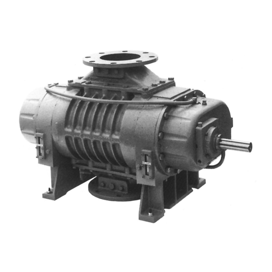
Mechanical Vacuum Boosters
Models
200
INSTALLATION
OPERATION
MAINTENANCE
REPAIR MANUAL
WARNING
DO NOT OPERATE
BEFORE READING MANUAL
07/2014
KMBD™ SERIES
240
400
540
720
850
1600
Tuthill Vacuum & Blower Systems
4840 West Kearney Street
Springfield, Missouri USA 65803-8702
o 417.865.8715 800.825.6937 f 417.865.2950
www.tuthillvacuumblower.com
Manual 1814-3
2000
2700
Advertisement
Table of Contents

Related Manuals for Tuthill KINNEY KMBD Series

Summary of Contents for Tuthill KINNEY KMBD Series
- Page 1 ® Mechanical Vacuum Boosters Models 1600 2000 2700 INSTALLATION OPERATION MAINTENANCE REPAIR MANUAL WARNING DO NOT OPERATE BEFORE READING MANUAL Tuthill Vacuum & Blower Systems 4840 West Kearney Street Springfield, Missouri USA 65803-8702 o 417.865.8715 800.825.6937 f 417.865.2950 www.tuthillvacuumblower.com 07/2014...
-
Page 2: Safety Precautions
• Booster heat can cause burns if touched. TUTHILL VACUUM AND BLOWER SYSTEMS — SPRINGFIELD, MO USA IMPORTANT In order to assure you of the full benefits of our product warranty, please complete, tear out and return the warranty registration card located on the back cover of this manual, or you can register your product online at: http://www.tuthillvacuumblower.com/index.cfm/contact-us/product-registration/... -
Page 3: Table Of Contents
TABLE OF CONTENTS SECTION PAGE SAFETY PRECAUTIONS INTRODUCTION DESCRIPTION INSTALLATION GENERAL SAFETY LUBRICATION PIPING CONNECTIONS COOLING WATER SPECIFICATIONS MOTOR DRIVES DIRECT COUPLED V-BELTS ELECTRICAL CONNECTIONS OPERATION STARTING OPERATING STOPPING MAINTENANCE GENERAL SPARE PARTS REPAIR SERVICE DISASSEMBLY AND ASSEMBLY INSTRUCTIONS 8-12 DISASSEMBLY —... -
Page 4: Introduction
INTRODUCTION CONGRATULATIONS on your purchase of a new Mechanical Vacuum Booster from Tuthill Vacuum & Blower Systems. Please examine the booster for shipping damage, and if any damage is found, report it immediately to the carrier. If the booster is to be installed at a later date make sure it is stored in a clean, dry location and rotated regularly. -
Page 5: Piping Connections
Figure 2 - Location of oil fill, drain and level plugs and level gauges Kinney KV-100 oil is recommended for use on boosters with typical vacuum applications. Consult Tuthill Vacuum & Blower Systems about oils for use where hazardous or chemically active materials may be present. NOTE: See “Frequently Asked Questions” on page 15 for additional information regarding lubrication. -
Page 6: Cooling Water Specifications
The air-cooled configuration requires no cooling water. However, INTERCONNECTING cooling water can be circulated through the seal adapter housing LINES on most models without modification to the booster. Cooling the bearing housing will prolong the life of the mechanical seal therein. An on-off valve should be provided on the incoming line and a SEAL regulating valve located in the drain line. -
Page 7: Electrical Connections
for an extended period of time. For INTAKE DISCHARGE DISCHARGE INTAKE more specific information consult the drive manufacturer. ELECTRICAL CONNECTIONS Wire the motor and other electrical devices such as solenoid valves and temperature switch to the proper voltage and amperage as indicated on the nameplate of each component DISCHARGE INTAKE... -
Page 8: Spare Parts
REPAIR SERVICE With proper care, Tuthill Vacuum & Blower Systems Mechanical Vacuum Boosters will give years of reliable service. The parts are machined to very close tolerances and require special tools by mechanics who are skilled at this work. Should major repairs become necessary, it is strongly recommended that the booster be returned to the factory for repair or to one of the authorized service facilities that specialize in vacuum booster repair. -
Page 9: Assembly - Kmbd-200, 400
Be sure they are in place. It is recommended that the gear end rotor shaft bearings be purchased from Tuthill Vacuum and Blower Systems, as they are specially ground to locate the rotors with correct end clearance Driven Gear relative to the gear end plate. - Page 10 direction, to the right. Carefully install gear end plate over rotor shafts. NOTE: The drive rotor should always be on the left side. Make sure the end plate feet are facing in the proper direction so the assembled unit will have the same drive shaft location as before. Mechanical Seal Series - Some earlier models used an O-ring [314] under the mating portion of the mechanical seal.
-
Page 11: Disassembly - Kmbd-540, 720, 850, 1600, 2000, 2700
mm) T.I.R. Install lockwire [49]. 20. Install bearing [50] on drive shaft with shield towards gear, and shim pack [118]. 21. Remove temporary cap screws from gear end plate and apply a bead of sealer around end plate (not cover), encircling all holes, and install gear cover [6] and secure with cap screws [26A]. -
Page 12: Assembly - Kmbd-540, 720, 850, 1600, 2000, 2700
It is recommended that the gear end rotor shaft bearings be purchased from Tuthill Vacuum & Blower Systems, as they are specifically ground to locate the rotors with correct end clearance relative to the gear end plate. Do not use standard bearings which have not been flush ground within .001”... - Page 13 sealer from carbon surface. Carefully wipe carbon with soft tissue and cleaning agent (acetone) before continuing assembly. Slinger Seal Series - Press in new oil slinger stators [79] if required. Stand rotors [1] on arbor press table with gear end shafts up. See Figure 10. Two keyways should point in the same direction, to the right.
-
Page 14: Frequently Asked Questions
20. Bend over lock tabs of gear lockwasher [36] and gear screw locks. KMBD-1600, 2000, and 2700 only - Mechanical Seal series (top drive only). Reinstall oil slinger [20] to lower rotor and secure with washer [136 & 80] and cap screw [396], if furnished. Not used on older models. - Page 15 is increased causing them to run hotter. Since it is thicker, it will not flow as readily into the gears and it will reduce the available backlash. Lubricants at our conditions are incompressible. What is the functional detriment if the oil is not serviced? If the lubricant is not serviced at the proper interval the shearing action in the bearing and the gears will begin to take their toll and the lubricant will thicken, making matters worse.
-
Page 16: Clearances
CLEARANCES Values shown in inches and millimeters. MODEL GEAR END FREE END INTERLOBE TIP-DOWEL TIP-PORT .006 - .010 240C .15 - .25 .003 - .005 CENTER .0065-.0075 .08 - .13 TIMED .165 - .190 .012 - .017 400C .30 - .43 400BP .004 - .007 .011 - .016... -
Page 17: Bypass Models - Kmbd-400Bp & Kmbd-720Bp
BYPASS MODELS - KMBD-400BP & KMBD-720BP PUMP MODEL KMBD-400BP KMBD-720BP Displacement Inlet/Outlet Motor Bypass valve 1-1/2 Valve item # 520356 B000 520357 B000 Tubing item # 520366 B000 520365 B000 Cracking pressure 50 Torr 50 Torr Max. Pressure Diff. 75 Torr 75 Torr These models are designed for applications such as vacuum packaging, where there is rapid cycling of evacuation of small volumes. -
Page 18: Drawings And Parts Lists
KMBD-200 AND KMBD-300 PARTS LIST ITEM MECHANICAL SLINGER ITEM MECHANICAL SLINGER PART DESCRIPTION PART DESCRIPTION SEAL SEAL SEAL SEAL Rotor Mechanical Seal Housing Spacer End Plate Oil Retainer — Drive End Cover Washer Free End Cover Locknut Timing Gear Set Pipe Plug Bearing Seal Adapter Housing... -
Page 19: Kmbd-540 And Kmbd-720 Parts List
KMBD-540 AND KMBD-720 PARTS LIST ITEM MECHANICAL SLINGER ITEM MECHANICAL SLINGER PART DESCRIPTION PART DESCRIPTION SEAL SEAL SEAL SEAL Rotor Washer Housing Locknut End Plate Pipe Plug Drive End Cover Shim Free End Cover Sleeve Timing Gear Set O-ring Bearing Spacer Bearing Screw... -
Page 20: Kmbd-850, 1600, 2000, And 2700 Parts List
KMBD-850, 1600, 2000, AND 2700 PARTS LIST ITEM MECHANICAL SLINGER ITEM MECHANICAL SLINGER PART DESCRIPTION PART DESCRIPTION SEAL SEAL SEAL SEAL Rotor Washer Housing Locknut End Plate Pipe Plug Drive End Cover Shim Free End Cover Sleeve Timing Gear Set O-ring Bearing Spacer... - Page 27 KMBD-240 AND KMBD-400 KMBD-240 AND KMBD-400 SEAL PRESSING TOOL SEAL PRESSING TOOL T32018-1 T32018-2 1.50 (38.1) 3.25 (82.6) (18.8) (12.7) (6.3) Ø 1.62 MIN R Ø 2.044 ± .001 (41.1) Ø 2.50 (51.90 ± .03) (63.5) Ø 1.885 ± .001 - A - Ø...
- Page 28 KMBD-850, 1200, 1600, 2000, 2700 KMBD-850, 1200, 1600, 2000, 2700 SEAL PRESSING TOOL SEAL PRESSING TOOL T11449-1 T11449-2 3.00 4.00 1.12 .835 MIN R Ø 3.151 Ø 3.147 ± .001 ± .001 Ø 2.50 .002 Ø 1.38 REF - A - Ø...
- Page 29 KMBD-850, 1200, 1600, 2000, 2700 DRIVE SHAFT SEAL ASSEMBLY FIXTURE T22180 5.00 1.00 2.00 1.63 .060 1.13 Ø 1.3760 Ø 2.00 REF MIN R .12 × 45° Ø 23/32 × 1.63 DP 1/2 NPT MATL P/N: CR1215R0-0200 × 5.25 LG TOLERANCES MATL: COLD ROLLED STEEL BAR, Ø...
-
Page 30: Warranty - Vacuum Products
WARRANTY – VACUUM PRODUCTS Subject to the terms and conditions hereinafter set forth and set forth in General Terms of Sale, Tuthill Vacuum & Blower Systems (the seller) warrants products and parts of its manufacture, when shipped, and its work (including installation and start-up) when performed, will be of good quality and will be free from defects in material and workmanship. - Page 31 IMPORTANT All mechanical vacuum boosters manufactured by Tuthill Vacuum & Blower Systems are date coded at time of shipment. In order to assure you of the full benefits of the product warranty, please complete, tear out and return the product registration card below, or you can visit our product registration web page at: http://www.tuthillvacuumblower.com/index.cfm/contact-us/product-registration/...
- Page 32 NECESSARY IF MAILED IN THE UNITED STATES BUSINESS REPLY MAIL FIRST-CLASS MAIL PERMIT NO. 2912 SPRINGFIELD MO POSTAGE WILL BE PAID BY ADDRESSEE ATTN. CUSTOMER SERVICE – VACUUM PRODUCTS TUTHILL VACUUM & BLOWER SYSTEMS PO BOX 2877 SPRINGFIELD MO 65890-2150...
Need help?
Do you have a question about the KINNEY KMBD Series and is the answer not in the manual?
Questions and answers