Table of Contents
Advertisement
Advertisement
Table of Contents

Related Manuals for REWIRE SECURITY DB3


Summary of Contents for REWIRE SECURITY DB3
-
Page 1: User Manual
DB3 Plug & Play GPS Tracker User Manual... -
Page 2: Table Of Contents
Package Contents ...................... 10 Basic Characteristics ....................10 Technical Features ..................... 12 Connection, Pinout ......................15 How To Insert SIM Card Into DB3 Plug&Play Device ..........15 Installing DB3 Plug&Play Drivers................17 Navigate LED ......................19 Status LED ........................19 ODB II ......................... - Page 3 System Settings ......................33 Record Settings ......................35 5.10 GSM Settings ......................36 5.10.1 GPRS ........................36 5.10.2 SMS ........................36 5.10.3 SMS Events ......................38 5.10.4 Operator List ....................... 40 5.11 Data Acquisition Mode Settings ................40 5.11.1 Scenarios Settings ....................44 5.11.2 Trip Settings ......................
- Page 4 6.1.12 Getparam #### ....................67 6.1.13 Setparam #### ....................67 6.1.14 Flush #,#,#,#,#,#,# ....................67 6.1.15 Banlist ........................ 68 6.1.16 Crashlog ......................69 6.1.17 Defevt ........................ 69 6.1.18 Battery ....................... 69 6.1.19 Cleardtc ......................69 6.1.20 Obdinfo ....................... 69 6.1.21 Faultcodes ......................
- Page 5 9.4.4 APN Password (ID=1244) ..................81 9.4.5 Main Server Domain (ID=1245) ................81 9.4.6 Backup Server Domain (ID=1241) ..............82 9.4.7 Target Main Server Port (ID=1246) ..............82 9.4.8 Target Backup Server Port (ID=1248) ..............83 9.4.9 Protocol (ID=1247) ..................... 83 9.4.10 Backup Server Protocol (ID=1249) ..............
- Page 6 9.6.12 Crash Detection (ID=1612) ................101 9.6.13 Trip (ID=1280) ....................102 9.6.14 Start Speed (ID=1281) ..................102 9.6.15 Ignition Off Timeout (ID=1282) ............... 102 9.6.16 Distance Mode (ID=1283) ................103 9.6.17 Trip Continuous Distance Counting ..............103 9.6.18 Odometer Value (ID=1284) ................103 9.6.19 Frame Border (ID=1020) ...................
- Page 7 9.9.2 OBD Fuel calculation method (ID=2101) ............115 9.9.3 Fuel type (ID=102) .................... 115 9.9.4 Engine Volume (ID=2104) ................. 115 9.9.5 Correction (ID=2103) ..................115 9.9.6 OBD I/O Configuration ..................116 9.9.7 I/O#1 Element SMS Event Configuration (ID=100) ..........117 Module installation .......................
-
Page 8: Introduction
Rewire Security is not responsible for any harm caused by using wrong cables for PC <-> DB3 Plug&Play connection. Warning! Do not use the DB3 Plug&Play device if it distracts the driver or causes inconvenience due to OBD II placement. -
Page 9: Safety Instructions
The device uses a 10 V...16 V DC power supply. The nominal voltage is 12 V DC. The allowed range of voltage is 10 V...16 V DC. To avoid mechanical damage, it is advised to transport the DB3 Plug&Play device in an impact-proof package. -
Page 10: Basic Description
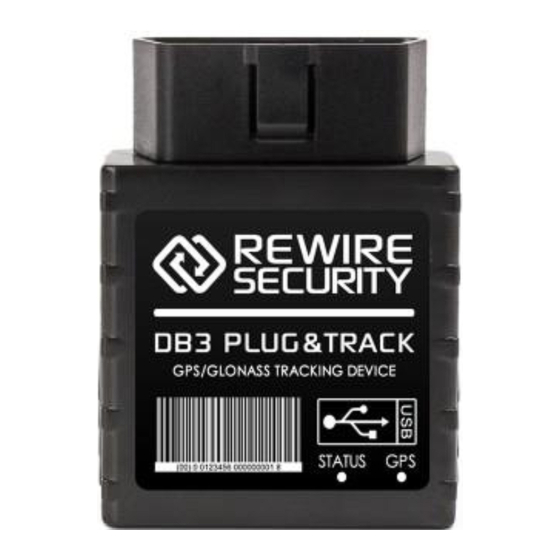
170mAh Li-ion battery; 2.2 Basic Characteristics GSM / GPRS features: DB3 TM11Q quad band module (GSM 850 / 900 / 1800 / 1900 MHz); GPRS class (text, data). Package content depends on Order Code, and can be customized by customer needs. - Page 11 GNSS features: TG3300 32 channel (or equivalent) receiver; Up to -161 dBm sensitivity. Hardware features: • Cortex®-M3 processor; • 1 MB internal Flash memory; • Built-in accelerometer; • OBD to UART interpreter ▪ Interface features: Power supply; 10 ÷ 16V; USB port;...
-
Page 12: Technical Features
Storage temperature: -40 °C ... +70 °C. Storage relative humidity 5 ... 95 % (no condensation) Table 1 DB3 Plug&Play specifications Energy consumption has been tested at 12V voltage. When in Deep Sleep mode no data storing and sending is activated. - Page 14 Figure 1 DB3 Plug&Play view & dimensions (tolerance ±1 mm) Absolute Maximum Ratings VALUE Min. Typ. Max. Unit CHARACTERISTIC DESCRIPT IO N Supply Voltage (Absolute Maximum Ratings) - 16 Digital Input Ignition Voltage (Absolute Maximum - 32 Ratings)
-
Page 15: Connection, Pinout
3. Connection, Pinout 3.1 How To Insert SIM Card Into DB3 Plug&Play Device Gently open DB3 Plug&Play case using screwdrivers... - Page 16 Remove DB3 Plug&Play case Insert SIM card as shown Insert battery wire to connector* Attach top housing cover...
-
Page 17: Installing Db3 Plug&Play Drivers
MS .NET Framework V3.5 or later (http://www.microsoft.com or • Installing drivers: Extract and run VCPDriver_V1.3.1_Setup.exe. This driver is used to detect DB3 Plug&Play device connected to the computer. Click 'Next' in driver installation window (figures below): Figure 2 Driver installation window... - Page 18 Figure 3 Driver installation window Setup will continue installing drivers and will display a window about the successful process at the end. Click 'Finish' to complete setup: Figure 4 Driver installation window You have now installed drivers for DB3 Plug&Play device successfully.
-
Page 19: Navigate Led
3.3 Navigate LED Behaviour Meaning Permanently switched on GNSS signal is not received Blinking every second Normal mode, GNSS is working GNSS is off because: turned Deep sleep mode GNSS antenna short-circuited 3.4 Status LED Behaviour Meaning Blinking every second Normal mode Blinking every 2 seconds Deep sleep mode... - Page 20 GND (-) Ground pin GND (-) Ground pin CAN H K-Line PWM BUS- CAN L L-Line Power range +(10...16) V DC to ground Power +(10 16) V DC Table 2 OBD II pinout description Figure 5 OBD II pinout...
-
Page 21: Usb
3.6 USB Mini USB connector Figure 6 Mini USB type B connector DB3 Plug&Play connected to PC creates an STM Virtual COM Port, which can be used as a system port (to flash firmware and configure the device): Figure 7 COM-Ports... -
Page 22: Firmware
Configurator. See configuration description for details. Contact sales manager to get the latest firmware. The device must be powered on. Connect DB3 Plug&Play to PC with the USB cable. Launch “Firmware Updater”, select COM port to which device is connected, click connect, and when IMEI and Firmware version fields are filled, start the update. -
Page 23: Operational Basics
5. Operational Basics 5.1 Operational Principals DB3 Plug&Play module is designed to acquire records and send them to the server. Records contain GNSS data and I/O information. The module uses GNSS receiver to acquire GNSS data and is powered by three data acquire methods: time-based, distance-based and angle-based method. -
Page 24: Sleep Modes
DB3 Plug&Play has to be configured to work in Sleep mode; The device must be synchronized time with GNSS satellites; DB3 Plug&Play has to be in „X on Stop Mode“ (Configured by Mode switch parameter); Ignition (Configured to be detected by Power Voltage, Ignition or Accelerometer) is off;... - Page 25 Active Data Link Timeout parameter, that DB3 Plug&Play could close GPRS link. Send period (Data Acquisition Mode settings) minus Active Data Link Timeout must be more than 90 sec., that DB3 Plug&Play could close GPRS link for at least 90 sec. USB cable is not connected.
-
Page 26: Virtual Odometer
5.3 Virtual Odometer The virtual odometer is used to calculate travelled distance in DB3 Plug&Play as a separate I/O element. If Between Records is selected as Distance Mode, then if DB3 Plug&Play detects movement, it starts counting distance using GNSS signal: every second it checks current location and calculates the distance between current and previous point. -
Page 27: Trip
Vehicle speed is equal or higher than 30km/h. Note: Green Driving Scenario is a factor in various cars and various drivers testing phase and can be subject to changes. Rewire Security is constantly working on the improvement of the functionality of the devices, and strongly recommends using the latest version of the firmware. -
Page 28: Geofencing
(Configured to be detected by Power Voltage, Ignition or Accelerometer). In case of theft, the car leaves Auto Geofencing zone without authorization DB3 Plug&Play device automatically sends high priority record to AVL application. 5.5 Configuration Installing DB3 Plug&Play for configuration:... -
Page 29: Configurator
Module configuration is performed over USB cable. Configuration process starts from starting DB3 Plug&Play Configurator program and then connecting to DB3 Plug&Play device via Connect button located on the top left corner of the configurator. If connected successfully IMEI, Version fields which were empty, now are filled with certain numbers depending on Modem IMEI and firmware version of your device (figure below). - Page 30 Figure 11 Configurator recommended configuration window Recommended device configuration is simple and is performed as follows: Connect device to configurator Enter GSM provided APN; APN user name; password; domain; Target server port Save configuration and disconnect Plug device to your vehic le and it is ready to use...
- Page 31 The user can also reset to default settings, by pressing Load Defaults button. After any modification of configuration settings it has to be saved to DB3 Plug&Play device, otherwise, it will not be written to the device.
- Page 32 The keyword is 4 – 10 symbol length. If the keyword is set, every time user reconnects DB3 Plug&Play to the USB port, the user will be asked to provide valid keyword when connecting DB3 Plug&Play to the configurator. The user is given 5 attempts to enter a keyword.
-
Page 33: Record Storage
It will send data later when GPRS is available again. Note that DB3 Plug&Play can have a memory full of records. In such case, it will start deleting oldest records in order to save new ones. Sending all the data records to the server may take some time. - Page 34 Records Settings, where the user can turn on saving/sending without time synchronization. LED Settings, where the user can enable/disable LED indication (both – GSM and GPS). This configuration parameter is saved in FLASH and when LED indication is disabled and the device is turned on, an indication will be enabled until configuration will be read from FLASH (maybe a few seconds delay).
-
Page 35: Record Settings
AVL application. Activate Data Link Timeout is used to set a timeout of the link between DB3 Plug&Play and AVL application termination. If DB3 Plug&Play has already sent all records it waits for new records before closing link. -
Page 36: Gsm Settings
Essential fields in ‘SMS’ are ‘SMS Login’ and ‘SMS Password’. The login and password are used with every SMS sent to DB3 Plug&Play. If login and password are not set, in every SMS sent to DB3 Plug&Play device two spaces before command have to be used (<space><space><command>). - Page 37 SMS login and password and authorized number list are used to protect DB3 Plug&Play module from unauthorized access. The module accepts messages only from a list of authorized numbers...
-
Page 38: Sms Events
I/O, OBD events. Figure 17 SMS Events configuration When any of the above events is triggered, DB3 Plug&Play sends a configured SMS message to a defined phone number. If SMS events are activated, but there are no numbers defined in the SMS events PreDefined Numbers list... - Page 39 The sent SMS messages format is according to: “Date Time EventText” For example, if DB3 Plug&Play is configured to send an SMS, when Digital Input 1 reaches High level, with priority High and configured to generate an event on both ranges enter and exit, then the sent SMS is: “2015/4/1 12:00:00 Digital Input 1”...
-
Page 40: Operator List
Figure 21. Operator list configuration 5.11 Data Acquisition Mode Settings Data Acquisition Modes are an essential part of DB3 Plug&Play device, it is also highly configurable. By configuration, the user defines how records will be saved and sent. There are three different modes: Home, Roaming and Unknown. - Page 41 The vehicle moving or stop state is defined by Mode Switch parameter. There are 3 ways for DB3 Plug&Play to switch between Vehicle on Stop and Vehicle Moving modes see section 5.711.
- Page 42 New GPRS context is opened if time is 10 minutes till time checked in the table. Therefore if all boxes are checked, DB3 Plug&Play is able to open new connection anytime. At scheduled time match DB3 Plug&Play...
- Page 43 GPRS session activity. If GPRS session is alive, DB3 Plug&Play sends data to the server according to Send period parameter. If it is not, DB3 Plug&Play checks if it is able to re-establish the session. Figure 21 GPRS Week Time configuration Device checks if the time between last saved record and the current time is equal or higher than Time-based acquire interval.
-
Page 44: Scenarios Settings
DB3 Plug&Play is able to collect records using three methods at the same time: time, distance and angle based data acquisition: Time-based data acquiring (Min. period) – records are being acquired every time when defined interval of time passes. Entering zero disables data acquisition depending on time. -
Page 45: Trip Settings
Figure 22 Scenarios configuration Green Driving: Eventual Record is generated when driving over allowed (configured) parameters. Over Speeding: Eventual Record is generated when driving over allowed (configured) speed and returning to normal speed. Excessive Idling Detection: If the ignition is ON and no movement, the event will be generated when TMO reached. - Page 46 Figure 24 Trip continuous distance counting parameter example The user can configure vehicle’s real odometer value. This value will be incremented by odometer functionality. If DB3 Plug&Play is used in another vehicle, the new value should be entered and synchronization reset by pressing...
-
Page 47: Geofencing Settings
Figure 25 Odometer value configuration 5.11.3 Geofencing Settings DB3 Plug&Play has 5 configurable Geofence zones and it can generate an event when defined Geofence zone border is crossed. Frame border – frame border is an additional border around Geofence zone. It... -
Page 48: Autogeofencing Settings
Figure 26 Geofence border Shape – can be rectangle or circle. Priority – the priority of Geofence event: low, high or panic. These levels define the priority of event information sending to the server. See I/O element description for more details about priorities. Generate event (On entrance, On exit, On Both) –... - Page 49 GNSS visibility. If vehicle stopped and activation timeout has passed, an AutoGeofence will be created around vehicle’s last position with set Radius value. AutoGeofence event generation works the same as Geofencing mentioned above. Figure 28 AutoGeofence configuration Note: DB3 Plug&Play operates in GMT:0 time without daylight saving.
-
Page 50: I/O Settings
5.12 I/O Settings When no I/O element is enabled, AVL packet comes with GNSS information only. After enabling I/O element(s) AVL packet along with GNSS information contains current value(s) of enabled I/O element. Name Description Ignition Logic: 0 / 1 External Voltage Voltage: mV, 0 –... - Page 51 Location Area code (LAC), it depends on GSM GSM Area Code operator. It provides a unique number which assigned to a set of base GSM stations. Max value: 65536 GPS HDOP Probability * 10; 0-500 GPS PDOP Probability * 10; 0-500 Eventual I/O elements (generate and send the record to the server only if appropriate conditions are met)
- Page 52 Priority (AVL packet priority) can be low, high or panic. Regular packets are sent as Low priority records. When low priority event is triggered, DB3 Plug&Play makes an additional record with an indication that the reason for that was I/O...
-
Page 53: Event Generating
High and Low levels – define I/O value range. If I/O value enters or exits this range, DB3 Plug&Play generates an event. “Generate event” parameter defines when to generate event – when value enters defined range, exits it or both. -
Page 54: Hysteresis
Generate event on interval enter, on interval exit, on both enter and exit Average constant 1 – 2 (4 Bytes) Figure 30 Digital Input event generation example 5.12.2 Hysteresis Figure 31 Hysteresis parameter configuration I/O elements can generate events according to hysteresis algorithm. If I/O event operand “Hysteresis”... -
Page 55: Obd Functionality Description
Figure 32 Event generation according to hysteresis algorithm 5.13 OBD Functionality Description 5.13.1 Supported OBD Protocols SAE J1850 PWM (41.6 kbaud); SAE J1850 VPW (10.4 kbaud); ISO 9141-2 (5 baud init, 10.4 kbaud); ISO 14230-4 KWP (5 baud init, 10.4 kbaud); ISO 14230-4 KWP (fast init, 10.4 kbaud);... - Page 56 Figure 33 available OBD IO elements on configurator window OBD IO list: Nr. Name Unit Size Multiplier “Number of DTC” “Calculated engine load value” 0 “Engine coolant temperature” °C “Short term fuel trim 1” -100 “Fuel pressure” “Intake manifold absolute pressure”...
- Page 57 “Runtime since engine 65535 s start” “Distance travelled MIL 65535 km on” “Relative fuel rail 51772 kPa X0.1 pressure” “Direct fuel rail pressure” 65535 kPa X0.1 “Commanded EGR” “EGR error” -100 “Fuel level” “Distance traveled codes 0 65535 km since cleared” “Barometric pressure”...
-
Page 58: Fuel Consumption Calculation
More information on OBD PIDs: http://en.wikipedia.org/wiki/OBD-II_PIDs 5.13.3 Fuel Consumption Calculation If data from OBD is not available (PID 94), DB3 Plug&Play can do calculations with other OBD parameters: Speed, Throttle, MAF, MAP, RPM, Engine Load. Calculation method can be configured: Figure 34 Fuel consumption on configurator window Auto –... -
Page 59: Accelerometer
6. SMS Command List All commands are case sensitive. While DB3 Plug&Play operates in Deep Sleep mode and the user tries to send SMS message it cannot arrive to DB3 Plug&Play device because GSM/GPRS module is disabled most of the time (wake up depends on Send Period parameter). -
Page 60: Sms Command List
6.1 SMS Command List Command Description Response getstatus Modem Status information getweektime Current device time, Day of Week and amount of minutes passed since the start of the week getops List of currently available GSM operator getcfgtime Date and Time of last successful configuration ggps Google Map Link information getgps... -
Page 61: Getstatus
flush #,#,#,#,#,#,# Initiates all data sending to specified target server 1.# - IMEI 2.# - APN 3.# - LOGIN 4.# - PASS 5.# - IP 6.# - PORT 7.# - MODE (0-TCP/1-UDP) banlist Banned operators information crashlog Device last information before unexpected reset bbread Device debug information delete_all_sms... -
Page 62: Getweektime
Phone Voice Call status: 0 – ready, 1 – unavailable, 2 – unknown, 3 – ringing, 4 – call in progress, 5 – asleep SIM Status: 0-ready, 1-pin, 2-puk, 3-pin2, 4-puk2 Connected to GSM Operator: numerical id of the operator Signal GSM Signal Quality [0-5] NewSMS... -
Page 63: Getcfgtime
Response Description details LIST Returns list of current available allowed operators. Example: GSM OP LIST: 0. 24602 6.1.4 Getcfgtime Response Description details Date/Time Returns last performed configuration date and time. Example: Last Configuration was performed on: 2010.4.15 5:45:19 6.1.5 Ggps Response Description details... -
Page 64: Getinfo
Response Description details GNSS Indicates valid (1) or invalid (0) GNSS data Count of currently available satellites Latitude (Last good Latitude) Long Longitude (Last good Longitude) Altitude Speed Ground speed, km/h Ground direction, degrees Date Current date Time Current GMT time Example: GNSS:1 Sat:7 Lat:54.71473 Long:25.30304 Alt:147 Speed:0 Dir:77 Date: 2007/8/24 Time: 13:4:36 6.1.7 Getinfo... -
Page 65: Getver
Failed link counter UPD Timeout counter Sent SMS Counter NOGNSS No GNSS Timer GNSS GNSS receiver state. 0 – OFF, 1 – restarting, 2 – ON but no fix, 3 – ON and operational, 4 – sleep mode Average satellites Reset Source Identification 1 –... -
Page 66: Allver
Modem App Ver Version of modem application Example: FW Ver:00.06.02 R0 Device IMEI:X DeviceID:00000E BL Ver:07.01 Modem FW Ver:TM11Q_R_01.04.07.00_001 HW: DB3 Plug&Play FULL GGG ST. 6.1.9 Allver Response Description details Device name Firmware version Firmware revision IMEI Firmware compile date... -
Page 67: Readio
Response Description details Digital Input 1 state Example: DI1:0 6.1.11 Readio # Response Description details I/O element ID Value I/O Element value Example: I/O ID:3 Value:0 6.1.12 Getparam #### Read parameter value. ID consists of 3 or 4 digits. Detailed list of parameters and IDs can be found in chapter number 8 “Parameter List”... -
Page 68: Banlist
# – APN; # – GPRS LOGIN; # – GPRS PASSWORD; # – IP; # – PORT; # – MODE (0 – TCP; 1 – UDP). Parameters are separated by a comma (no spaces needed). In case you don’t need to enter the parameter (Login/Pass) – do not put space, simply put a comma and write next parameter. -
Page 69: Crashlog
6.1.17 Defevt This SMS command resets SMS Events configuration to default. Example: SMS Event default parameters loaded. 6.1.18 Battery Returns DB3 Plug&Play battery information. Example: BatState: 1 FSMState: ACTIVE ChargerIC: CHARGING ExtV: 14020 BatV: 3800 BatI: 50 PCBTemp: 35.2. 6.1.19 Cleardtc Clears all vehicle stored trouble codes and turns the MIL off. -
Page 70: Faultcodes
Example: “P0100,P0200,P0300,C0300,B0200,U0100”. 7. GPRS Commands It is possible to send commands to DB3 Plug&Play using GPRS. When DB3 Plug&Play sends records periodically to a server, a message could be sent from the server and DB3 Plug&Play will reply to it. - Page 71 #GET Get GSM operator to which device is connected NETWORK #GET IMSI Get IMSI of the device #DO REPORT Save a record Reset FM5302 or GPS module, XXX – FM5X or GPS RESET=XXX #GET Get operator from the list of a certain profile, X – profile, ROAMINGX=Y Y –...
- Page 72 #SET Set MinAngle to the configuration of a certain profile, X – REPANGX=Y profile, Y – MinAngle value #GET Get SendPeriod from the configuration of a certain SENDPERIODX profile, X – profile #SET Set SendPeriod to the configuration of a certain profile, X SENDPERIODX=Y –...
- Page 73 getops List of currently used and available GSM operators readops# Emergency gsm operator readout from active profile # – 1,2,3 – operators [1-20] – operators [21-40] – operators [41-50] getnmeainfo Nmea error debug sms getcfgtime Date and Time of last successful configuration getgps Current GPS data and time loadprofile#...
-
Page 74: Debug Mode
GPRS commands, please contact your local sales representative. 8. Debug mode DB3 Plug&Play is able to transmit its current state when connected to PC using the USB cable. It is used to detect errors and provide information to possible solutions when operating as unexpected. -
Page 75: Parameter List
Log’ button and save a new file. Enable DTR and then click ‘Connect’ to start receiving messages from DB3 Plug&Play. Also, you can log NMEA data directly. To get NMEA data, simply enter the following command into the command field: .log_nmea:1$0a. -
Page 76: Sleep Timeout (Id=1001)
9.2.2 Sleep Timeout (ID=1001) Sleep timeout is time after which DB3 Plug&Play goes to sleep or deep sleep if other requirements are met. It is measured in minutes. Maximum Recommended Goes with (depends on) Value... -
Page 77: Static Navigation Settings (Id=1004)
Level (1007) 9.2.5 Static navigation settings (ID=1004) When static navigation is enabled, DB3 Plug&Play filters out GPS jumps, when it is not moving. When it is disabled, it does not make any changes to collected GPS data. 0 - disabled (default); 1 - enabled. -
Page 78: Power Voltage High Level (Id=1007)
Ignition Source (ID=1003) 30000 Power Voltage Level High Level (1007) 9.2.8 Power Voltage High Level (ID=1007) When ignition source is selected as Power Voltage High level for ignition detection must be set. Minimum Maximum Recommended Goes with (depends on) Value value value parameters... -
Page 79: Records Parameters
9.3 Records Parameters 9.3.1 Sorting (ID=1010) Record sorting parameter is responsible for record sorting order. Value of 0 arranging data starting from the newest, while the value of 1 arranging data starting from the oldest. Minimum Maximum Recommended Goes with (depends on) Value value value... -
Page 80: Gsm Parameters
depends solely on the operator. For example, if active data link timeout is set to maximum, 259200 seconds (72 hours), and the device sends data to the server every 86400 seconds (24 hours), the operator might disconnect the link earlier and the device will have to connect to the server anew. This may cost extra, depending on the operator GPRS data charge. -
Page 81: Apn Username (Id=1243)
APN Password (ID=1244) 9.4.3 APN Username (ID=1243) The parameter defines APN username. In case the operator does not use the username for login, the value should be empty. Minimum Maximum Recommended Goes with (depends on) Value value value parameters type value 30 char GPRS content activation... -
Page 82: Backup Server Domain (Id=1241)
Minimum Maximum Recommended Goes with (depends on) Value value value parameters type value 50 char GPRS content activation string (ID=1240) Main Server S8[16] Domain (ID=1245) 9.4.6 Backup Server Domain (ID=1241) Parameter defines AVL data destination server IP address for backup server. Minimum Maximum Recommended... -
Page 83: Target Backup Server Port (Id=1248)
Target Main Server Port (1246) GPRS content activation (ID=1240) Main Server Domain (ID=1245) 9.4.8 Target Backup Server Port (ID=1248) Parameter defines AVL data destination backup server port number. Minimum Maximum Recommended Goes with (depends on) Value value value parameters type value GPRS content activation (ID=1240) -
Page 84: Backup Server Protocol (Id=1249)
GPRS content activation (ID=1240) 9.4.10 Backup Server Protocol (ID=1249) Parameter defines GPRS data transport protocol for backup server. Module can use TCP or UDP transport protocol to send data to server. For TCP protocol value is 0, for UDP protocol value is 1. Minimum Maximum Recommended... -
Page 85: Sms Data Sending Settings (Id=1250)
9.4.13 SMS Data Sending Settings (ID=1250) Parameter allows or does not allow sending AVL data using binary SMS. If SMS use is not allowed value is 0 and 1 if SMS use is allowed. Minimum Maximum Recommended Goes with (depends on) Value value value... -
Page 86: Location By Call (Id=1251)
9.4.16 Location by Call (ID=1251) The user can select what to do with the incoming call: 0-Do nothing (default), 1- Just hang up, 2hang up with position SMS. Minimum Maximum Recommended Goes with (depends on) Value value value parameters type value S8[17] 9.4.17 Operator List (ID=1271) - Page 87 2592000 9.5.1.2 Min Saved Records (ID=1543) This parameter defines the minimum number of records in one data packet that can be sent to the server. It has higher priority than Data Send Period (ID=1544). Minimum Maximum Recommended Goes with (depends on) Value value value...
-
Page 88: Home Network Gsm Operator Code "Vehicle Moving" Parameters
context is closing (for example changing network) it is allowed to open it only at a defined time. It is possible to allow connections every 10 minutes up to once per day. Example value: 7F,FF,FF,FF,FF,FF,FF,FF,FF,FF,FF,FF,FF,FF,FF,FF,FF,FF,FF Schedule parameter format: Time is defined as 19-byte array. The first byte of array defines weekdays;... - Page 89 Min Distance (ID=1551) 2592000 Min Angle (ID=1552) GPRS Week Time (ID=1555) 9.5.2.2 Min Distance (ID=1551) This parameter indicates distance in meters in order to acquire new record. The record is stored when the distance between previous records is greater than parameters value.
- Page 90 Min Period (ID=1550) Min Distance (ID=1551) GPRS Week Time (ID=1555) 9.5.2.4 Min Saved Records (ID=1553) This parameter defines the minimum number of records in one data packet that can be sent to the server. It has higher priority than Data Send Period (ID=1554).
-
Page 91: Roaming Network Gsm Operator Code "Vehicle On Stop" Parameters
Read GPRS Week Time (ID=1545) 9.5.3 Roaming Network GSM Operator Code “Vehicle On STOP” Parameters 9.5.3.1 Min Period (ID=1560) This parameter indicates time interval in seconds in order to acquire new record. If the value is 0 it means no records by min period will be saved. Minimum Maximum Recommended... -
Page 92: Roaming Network Gsm Operator Code "Vehicle Moving" Parameters
(ID=1563) GPRS Week Time (ID=1565) 9.5.3.4 GPRS Week Time (ID=1565) Read GPRS Week Time (ID=1545) 9.5.4 Roaming Network GSM Operator Code “Vehicle MOVING” Parameters 9.5.4.1 Min Period (ID=1570) This parameter indicates time interval in seconds in order to acquire new record. - Page 93 value Min Period (ID=1570) Min Angle (ID=1572) 65535 GPRS Week Time (ID=1575) 9.5.4.3 Min Angle (ID=1572) This parameter indicates angle in degrees in order to acquire new record. If angle difference between last recorded coordinate and current position is greater than the defined value, a new record is stored. This parameter is operational when speed is higher than 10km/h.
-
Page 94: Unknown Network Gsm Operator Code "Vehicle On Stop" Parameters
GPRS Week Time (ID=1575) 9.5.4.5 Send Period (ID=1574) This parameter indicates frequency (time interval in seconds) of sending data to the server. Minimum Maximum Recommended Goes with (depends on) Value value value parameters type value Min Saved Records 2592000 (ID=1573) GPRS Week Time (ID=1575) 9.5.4.6 GPRS Week Time (ID=1575) Read GPRS Week Time (ID=1545) -
Page 95: Unknown Network Gsm Operator Code "Vehicle Moving" Parameters
9.5.5.2 Min Saved Records (ID=1583) This parameter defines the minimum number of records in one data packet that can be sent to the server. It has higher priority than Data Send Period (ID=1584). Minimum Maximum Recommended Goes with (depends on) Value value value... - Page 96 Minimum Maximum Recommended Goes with (depends on) Value value value parameters type value Min Distance (ID=1571) 2592000 Min Angle (ID=1572) GPRS Week Time (ID=1575) 9.5.6.2 Min Distance (ID=1591) This parameter indicates distance in meters in order to acquire new record. The record is stored when the distance between previous records is greater than parameter’s value.
- Page 97 Min Period (ID=1570) Min Angle (ID=1572) GPRS Week Time (ID=1575) 9.5.6.4 Min Saved Records (ID=1593) This parameter defines the minimum number of records in one data packet that can be sent to the server. It has higher priority than Data Send Period (ID=1594).
-
Page 98: Features Parameters
9.5.6.6 GPRS Week Time (ID=1595) Read GPRS Week Time (ID=1545) 9.6 Features Parameters 9.6.1 Scenarios Enable (ID=1600) The device can operate in its scenario according to selected value: No Scenario selected (value 0); Green Driving selected (value 1), Overspeeding selected (value 2), Green Driving &... -
Page 99: Max Angular Velocity (Id=1604)
0.25 0.85 0.35 Scenarios Enable Float (ID=1600) 9.6.4 Max Angular Velocity (ID=1604) It is max allowed cornering angle which can be reached while cornering without triggering harsh cornering event. Minimum Maximum Recommended Goes with (depends on) Value value value parameters type value Scenarios Enable... -
Page 100: Time To Stationary (Id=1608)
Time to movement (ID=1609) 9.6.7 Time to Stationary (ID=1608) If ignition is ON and no movement, the event will be generated when TMO reached. This functionality is 1-enabled, 0-disabled (default). Minimum Maximum Recommended Goes with (depends on) Value value value parameters type value... -
Page 101: Alarm (Id=1610)
Minimum Maximum Recommended Goes with (depends on) Value value value parameters type value 9.6.10 Alarm (ID=1610) The alarm can be set to generate low or high priority event: 0 – disabled (default), 1 – low priority event, 2 – high priority event. Minimum Maximum Recommended... -
Page 102: Trip (Id=1280)
9.6.13 Trip (ID=1280) This parameter enables the ability to detect START and STOP of the trip. Possible values are: 0 – disabled (default), 1 – standard, 2 – private/business. Minimum Maximum Recommended Goes with (depends on) Value value value parameters type value 9.6.14 Start Speed (ID=1281) -
Page 103: Distance Mode (Id=1283)
9.6.17 Trip Continuous Distance Counting This parameter removed from DB3 Plug&Play firmware version >00.06.xx. The odometer is always counting distance continuously (from Trip start to Trip stop) when Distance Mode parameter is set to continuous. 9.6.18 Odometer Value (ID=1284) -
Page 104: Geofence Zone #1 Shape (Id=1030)
1000000 1000 All Geofencing parameters 9.6.20 Geofence Zone #1 Shape (ID=1030) Geofence shape parameter can be: circle – value 0; rectangle – value 1. Minimum Maximum Recommended Goes with (depends Value value value on) parameters type value All Geofencing parameters 9.6.21 Geofence Zone #1 Priority (ID=1031) Parameter defines Geofence priority... -
Page 105: Geofence Zone #1 Longitude (X1) (Id=1033)
On both – value 3. Minimum Maximum Recommended Goes with (depends on) Value value value parameters type value All Geofencing parameters 9.6.23 Geofence Zone #1 Longitude (X1) (ID=1033) The parameter has two meanings dependent on zone shape. If the shape is a rectangle, then ID=10333 is left down corner X coordinate. -
Page 106: Geofence Zone #1 Longitude (X2) (Id=1035)
All Geofencing Float parameters 9.6.25 Geofence Zone #1 Longitude (X2) (ID=1035) The parameter has two meanings depending on zone shape. If the shape is a rectangle, then ID=1035 is right upper corner X coordinate. If the shape is a circle, then ID=1035 is the radius of a circle with the center of ID=1033 and ID=1034. -
Page 107: Enable/Disable (Id=1101)
GeoFence Geofence Zone Zone’s Number parameters 1030-1036 1040-1046 1050-1056 1060-1066 1070-1076 9.6.27 Enable/Disable (ID=1101) Enable – value 1; disable – value 0. Minimum Maximum Recommended Goes with (depends on) Value value value parameters type value 9.6.28 Activation Timeout (ID=1102) The parameter represents AutoGeofencing activation timeout in seconds. -
Page 108: Autogeofence Event Priority (Id=1103)
9.6.29 AutoGeofence event Priority (ID=1103) The parameter defines AutoGeofence event priority: 0 is low, 1 – high. Minimum Maximum Recommended Goes with (depends on) Value value value parameters type value Enable/Disable (ID=1101) AutoGeofence event generating (ID=1104) 9.6.30 AutoGeofence event generating (ID=1104) Generate event: 0 –... -
Page 109: Accelerometer Parameters
9.7 Accelerometer parameters 9.7.1 Acceleration Range Configuration (ID=1290) Parameter represents range of movement detection in G force. Minimum Maximum Recommended Goes with (depends on) Value value value parameters type value Ignition Source (ID=1003) U32 9.7.2 Movement Filter Start (ID=1293) The parameter represents how long it takes to generate movement event in seconds. -
Page 110: I/O Parameters
9.8 I/O parameters I/O properties are additional data sources which are recorded along with usual GNSS data. 9.8.1 I/O#1 Property Parameter (ID=1300) Parameter defines I/O property value. Possible values: enabled (1), disabled (0). Minimum Maximum Recommended Goes with (depends on) Value value value... -
Page 111: I/O#1 High Level (Id=1302)
I/O#1 property parameter (ID=1300) I/O#1 High level (ID=1302) I/O#1 Low level (ID=1303) I/O#1 logic operand (ID=1304) I/O#1 averaging length (ID=1305) 9.8.3 I/O#1 High Level (ID=1302) The parameter defines the high value of triggered I/O property. This parameter is used to set thresholds for I/O properties to generate events. Minimum Maximum Recommended... -
Page 112: I/O#1 Low Level (Id=1303)
9.8.4 I/O#1 Low level (ID=1303) The parameter defines the low value of triggered I/O property. This parameter is used to set thresholds for I/O properties to generate events. Minimum Maximum Recommended Goes with (depends on) Value value value parameters type value I/O#1 property parameter (ID=1300) -
Page 113: I/O#1 Averaging Length (Id=1305)
I/O#1 averaging length (ID=1305) 9.8.6 I/O#1 Averaging Length (ID=1305) The parameter defines I/O property sample length to average. If no averaging needed default value is 1. Minimum Maximum Recommended Goes with (depends on) Value value value parameters type value I/O#1 property parameter (ID=1300) I/O#1 priority (ID=1301) -
Page 114: Obd Parameters
I/O#3 – External Voltage 1330 – 1335 I/O#4 – Movement 1340 – 1345 I/O#5 – Trip Distance 1350 – 1355 I/O#6 – Active GSM 1360 – 1365 Operator I/O#7 – GPS Speed 1370 – 1375 I/O#8 – Data Mode 1380 – 1385 I/O#9 –... -
Page 115: Obd Fuel Calculation Method (Id=2101)
9.9.2 OBD Fuel calculation method (ID=2101) 0 – Disabled (default); 1 – Auto; 2 – PID; 3 – Calculate by OBD data; 4 – Calculate by norm value (not implemented yet). Minimum Maximum Recommended Goes with (depends on) Value value value parameters type... -
Page 116: Obd I/O Configuration
Default value is 100 (it corresponds to actual value 1). SMS configuration value is multiplied by 100. Minimum Maximum Recommended Goes with (depends on) Value value value parameters type value OBD Fuel calculation 1000 method (ID=2101) 9.9.6 OBD I/O Configuration OBD I/O configuration is the same as general I/O (See I/O parameters). -
Page 117: I/O#1 Element Sms Event Configuration (Id=100)
2260 – 2265 2270 – 2275 2280 – 2285 2290 – 2295 2300 – 2305 2310 – 2315 2320 – 2325 2330 – 2335 2340 – 2345 For example, SMS command “setparam 2250 12” will configure Engine RPM PID for 11th slot. Then other parameters can be configured similar to I/O parameters: 2251 –... - Page 118 Other I/O element SMS events can be configured in same logic. All I/O element SMS event IDs are listed in the next table. OBD Iox (x – any number between 1 to 20) defines SMS event text for configured OBD IO slot. Element name (default SMS Event Text)
- Page 119 OBD IO2 OBD IO3 OBD IO4 OBD IO5 OBD IO6 OBD IO7 OBD IO8 OBD IO9 OBD IO10 OBD IO11 OBD IO12 OBD IO13 OBD IO14 OBD IO15 OBD IO16 OBD IO17 OBD IO18 OBD IO19 OBD IO20 Geo Zone 1 Geo Zone 2 Geo Zone 3 Geo Zone 4...
-
Page 120: Module Installation
Locate OBD-II connector in your car (see car owner’s manual for the location of the connector); Plug in DB3 Plug&Play device in OBD-II connector or use an optional extension cable (Figure 37); If status and navigate LED lights turn on, the device is ready to use. - Page 121 (if there is not enough space for the device near the OBD-II connector, an extension cable may be necessary, which can be ordered as an accessory – not included in the package). Figure 38 Correct placement of DB3 Plug&Play...
- Page 122 Start Move Timeout – is a time interval required for the accelerometer to be in the moving state, to consider the vehicle as moving. Warning! Do not use the DB3 Plug&Play device if it distracts the driver or causes inconvenience due to OBD II placement. The device must not interfere with the driver! Thank you for purchasing DB3 Plug&Play GPS Tracker.
Need help?
Do you have a question about the DB3 and is the answer not in the manual?
Questions and answers