Table of Contents
Advertisement
Quick Links
GRD
GRD-2
DELTA-3
GATE
RECEIVER
Installation Instructions
For more information: www.devancocanada.com
(800) 421-1587 • www.linearcorp.com
STEP 2A
GRD & GRD-2 Channel 1 code
setting.
T o s e t a c o d e , s e l e c t a n y v a l i d
combination of ON and OFF positions for the
switch keys numbered 1- 8. Use a paper clip to
set the eight keys.
SET CODE
SWITCH KEYS
CHANNEL ONE
SWITCH KEYS
THIS SWITCH
HAS 2, 3 & 6 ON
DO NOT USE:
ALL ON; ALL OFF;
ALT ON/OFF, OR OFF/ON
STEP 5
C o n n e c t r e c e i v e r t o p o w e r .
Connect the red power input wire to the 24VDC
radio power and the black wire to the common
terminal on the gate operator. Alternately connect
wires to a 12-24 VAC transformer.
GATE OPERATOR
MANUAL
ACCESS REQUEST
OBSTACLE
BLACK
1
COMMON
2
RELAY
RED
24 V RADIO POWER
3
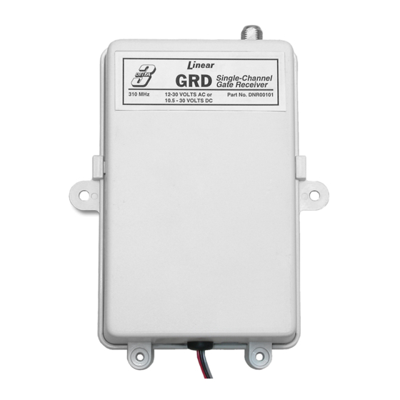
INPUT VOLTAGE REQUIREMENT
12 TO 30 VOLTS AC
10.5 TO 30 VOLTS DC
DESCRIPTION
The GRD is a digital receiver designed for use with automatic
gate operators or systems where a remote antenna is
needed. The GRD-2 will operate two gates, one gate and
an obstacle sensor, or channel one can open the gate and
channel two can close the gate.
All of the Delta-3 transmitters, including the two and
four-channel transmitters, are compatible with the GRD.
The Delta-3 radio format provides 256 different digital codes.
The codes are set using the 8-position coding switches in
the units. In order to avoid the possibility of duplicating codes
in adjacent systems, factory set codes should not be used.
The receivers can operate from 12-30 volts AC or 10.5-30
volts DC and are normally powered from the gate operator.
The relay contact(s) are rated at 5 amps @ 32 volts AC/DC
NEC Class 2 circuit.
STEP 2B
GRD-2 Channel 2 code setting.
Select any valid combination of ON and OFF
positions for each of the switch keys numbered
1 - 8. Use a different code combination than that
used for channel one switch.
SET CHANNEL TWO
CODE SWITCH KEYS
CHANNEL TWO
SWITCH KEYS
THIS SWITCH
HAS 2, 4 & 6 ON
DO NOT USE:
ALL ON; ALL OFF;
ALT ON/OFF, OR OFF/ON
STEP 6
Mounting the receiver. U s e t h e
screws provided to mount the receiver within the
operator housing. This provides protection from
the elements. Secure case with case screws.
MOUNT RECEIVER
INSIDE GATE
HOUSING
SECURE CASE
CLOSED WITH TWO
SCREWS AT BOTTOM
OF CASE
The GRD has a "F" connector for attaching an antenna. The
receiver is supplied with a 9-inch local antenna, a three foot
75 ohm coaxial cable, and a bulkhead connector for
mounting the antenna outside the gate operator enclosure.
RECEIVER
3-FOOT
CABLE
CASE SCREWS
MOUNTING
HARDWARE
LOCAL
NUT
ANTENNA
BULKHEAD
CONNECTOR
STEP 3
Transmitter code setting. Locate
the coding switch on the transmitter and set the
eight keys identical to those on the desired
channel of the receiver. Be sure they match
exactly. I f u s i n g a t w o o r f o u r - c h a n n e l
transmitter, refer to the coding instructions
included with the transmitter for proper system
coding.
REMOVE BATTERY
ACCESS DOOR
SWITCHES IN
TRANSMITTER
CODING
SWITCH
THIS SWITCH
HAS 2, 3 & 6 ON
STEP 7
Connect antenna. C o n n e c t t h e
coaxial cable to the "F" connector on the receiver.
Drill a 3/8" hole on the top of the operator housing
for the bulkhead connector. Insert the connector
and secure it with the nut and lock washer.
Connect the cable and antenna to the bulkhead
connector.
SLIDE WEATHER
RESISTANT CAP
OVER CONNECTION
CONNECT COAXIAL
CABLE TO "F"
CONNECTOR
INSERT BULKHEAD
CONNECTOR THROUGH
OPERATOR HOUSING
SECURE CONNECTOR
TO HOUSING USING
WASHER AND NUT
CONNECT CABLE TO
BULKHEAD CONNECTOR
STEP 1
Open receiver case. To open case,
squeeze sides of case and rotate upward.
SQUEEZE BOTH SIDES AT TABS
WASHER
AND TILT UPWARD
STEP 4
Connect receiver relay output.
Connect the appropriate channel wires (Ch. 1 -
two gray wires), (Ch. 2 - two yellow wires) to the
appropriate activation terminals on the gate
operator.
GATE OPERATOR
1
CHANNEL
2
ONE
GRAY
3
OBSTACLE INPUT
YELLOW
1
CHANNEL
TWO
2
LINEAR LIMITED WARRANTY
This Linear product is warranted against defects in material and workmanship for twelve
(12) months. The Warranty Expiration Date is labeled on the product. This warranty
extends only to wholesale customers who buy direct from Linear or through Linear's
normal distribution channels. Linear does not warrant this product to consumers.
Consumers should inquire from their selling dealer as to the nature of the dealer's
warranty, if any. There are no obligations or liabilities on the part of Linear
Corporation for consequential damages arising out of or in connection with use
or performance of this product or other indirect damages with respect to loss of
property, revenue, or profit, or cost of removal, installation, or reinstallation. All
implied warranties, including implied warranties for merchantability and implied
warranties for fitness, are valid only until Warranty Expiration Date as labeled on the
product. This Linear Corporation Warranty is in lieu of all other warranties express
or implied.
All products returned for warranty service require a Return Product Authorization
Number (RPA#). Contact Linear Technical Services at 1-800-421-1587 for an RPA#
and other important details.
IMPORTANT !!!
Linear radio controls provide a reliable communications link and fill an important need
in portable wireless signaling. However, there are some limitations which must be
observed.
1
For U.S. installations only: The radios are required to comply with FCC Rules and
Regulations as Part 15 devices. As such, they have limited transmitter power and
therefore limited range.
1
A receiver cannot respond to more than one transmitted signal at a time and may be
blocked by radio signals that occur on or near their operating frequencies, regardless of
code settings.
1
Changes or modifications to the device may void FCC compliance.
1
Infrequently used radio links should be tested regularly to protect against undetected
interference or fault.
1
A general knowledge of radio and its vagaries should be gained prior to acting as a
wholesale distributor or dealer, and these facts should be communicated to the ultimate
users.
Copyright © 2003 Linear Corporation
MANUAL ACCESS
REQUEST
COMMON
RELAY
24 V RADIO POWER
COMMON
OBSTACLE
220812 A
Advertisement
Table of Contents

Related Manuals for Linear GRD


Summary of Contents for Linear GRD
-
Page 1: Installation Instructions
Insert the connector Consumers should inquire from their selling dealer as to the nature of the dealer’s warranty, if any. There are no obligations or liabilities on the part of Linear wires to a 12-24 VAC transformer. - Page 2 HOW TO ORDER REPAIR PARTS DEVANCO CANADA 19192 HAY ROAD, UNIT Q SUMMERSTOWN, ON K0C 2E0 TOLL FREE: 855-931-3334 www.devancocanada.com WHEN ORDERING REPAIR PARTS PLEASE SUPPLY THE FOLLOWING INFORMATION: 3 PART NUMBER 3 DESCRITPION 3 MODEL NUMBER...
Need help?
Do you have a question about the GRD and is the answer not in the manual?
Questions and answers