Table of Contents
Advertisement
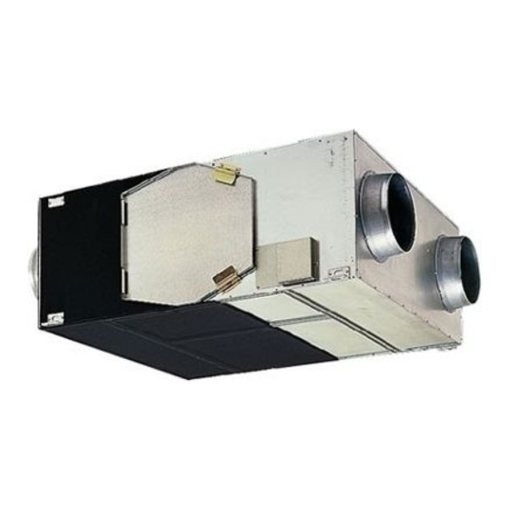
LOSSNAY
HANDBOOK
Model:
Model:
Model:
LGH-15RX
LGH-25RX
LGH-35RX
LGH-50RX
LGH-65RX
LGH-80RX
LGH-100RX
LGH-150RX
LGH-200RX
Remote controller
PZ-60DR-E
Filter
(Parts number is not set.)
PZ-25RF
PZ-50RF
PZ-80RF
Repair work must be performed by
the manufacturer, its service agent or
a similarly qualified person in order to
avoid hazards.
December 2012
-E
5
-E
5
-E
5
-E
5
-E
5
Nameplate
-E
5
-E
5
-E
5
-E
5
Nameplate
(Parts number is not set.)
-E
PZ-35RF
8
-E
PZ-65RF
8
-E
PZ-100RF
8
No. U155-A
-E
8
-E
8
-E
8
Advertisement
Table of Contents


Need help?
Do you have a question about the LGH-15RX5-E and is the answer not in the manual?
Questions and answers