
Subscribe to Our Youtube Channel
Related Manuals for Mitsubishi VD-10Z4T


Summary of Contents for Mitsubishi VD-10Z4T
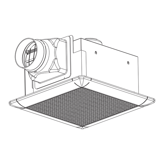
- Page 1 VENTILATING FAN MODEL: MANUAL AND INSTALLATION PROCEDURE PRODUCT APPEARANCE ADDITIONAL PART SCREW (9 PCS) REMARK : IS THE ALPHABET OF DEVELOPEMENT NUMBER CAREFULLY READ INSTALLATION MANUAL AND THE PRODUCT SHOULD BE INSTALLED BY THE SPECIALIZED TECHNICIAN.
-
Page 2: Essential Safety Precautions
ESSENTIAL SAFETY PRECAUTIONS WARNING FAILURE TO COMPLY DEATH OR BODILY INJURY MAY RESULT. 1. Do not use the ventilator when damages found on wire or other components. This may cause fire and electric shock. 2. Do not switch on the ventilator when the assembling is not completed with all components such as airguide and propeller as bodily injury may result. - Page 3 In case of installation at high temperature area, the Should inclined install smoke pipe by additional duct capacity of insulator parts such as motor, capacity higher than smoke pipe on the wall might drop and be cause of electric leakage. 1mm/100mm to protect the rain water.
- Page 4 (A3) To install the wing of additional duct under sub (A2) To take off additional duct as the arrow beam and fix additional duct with main duct. Then direction as Figure.3 fix additional duct with sub beam at “A” position with screw as Figure.4 ADDITIONAL DUCT Remark...
- Page 5 Table shown dimension of position of “L” Fix plate each model as followed MODEL Dimension Dimension Dimension Unit:mm. As shown at Figure.9 L fix plate Figure. SCREW P-08TK (ADDITIONAL PART) L FIX PLATE HOOK NUT (B1.2) To fix the product with hook nut and horizontal install the product as right picture.
- Page 6 (B2.2) To set 2 wooden parts with sub frame (B2.3) To Install sub frame to ceiling with Hook nut as by using screws as the Figure.13 the Figure.14 Caution :Do not obstruct hook nut-hole on sub frame. HOOK-NUT SUB FRAME Figure.
- Page 7 TO INSTALL PIPE FROM BODY TO WELL EXHAUST PIPE To adhere aluminium tape at connecting point TAPE between exhaust pipe and additional duct to protect air leakage as Figure.21 DUCT Figure. ADDITIONAL PART(NOT INCLUDE ON PRODUCT) “L” fix plate, Sub frame, Duct (Iron, plastic, Aluminium, Stainless steel), Hood. TO INSTALL LEAD WIRE SHOULD BE DONE AS NECESSARY LEAD WIRE INATALLATION CAUTION 1.Fan and lead wire installation should be suggested by service center or specialize...
- Page 8 VENTILATOR MAIN UNIT HOOK Thermal fuse SLIDE COVER WALL SWITCH is obtained from hardware store. Remark : 1. Installation location of circuit breaker should be easy to operation and shut off. LEAD WIRE 2. The circuit breaker shall have a contact separation in 1.6 mm or all poles and provide full disconnection under 2.0 mm...
- Page 9 TERMINAL Model: as Figure. COVER SCREW (1) Remove screw and unlock cover, weave VVF (Ø1.6, Ø2.0) through rubber button until it can be completely passed. (2) The product is used in high humidity area, the ground wiring should be installed. LEAD WIRE (3) To lock the cover and fix to screw.
-
Page 10: Operating Procedure
USAGE For VD-10Z , VD-10Z -C, VD-15Z VD-15Z -C, VD-15ZP 4T , CAUTION USAGE Various parts are made from plastic material, do not In case of installed in restroom having hot bathtub, bring flammable objects to be near them that they after draining the hot water, please cover bathtub might possibly be deformed or melted. - Page 11 REPAIRING PRODUCT 1. This product must not be assembled under any circumstances. Only authorized repair technicians are qualified to conduct diassembly and repairs. (Failure to heed this warning may result infire, electric shock or injury.) 2. Must use genuine spare part from Service center or Sales Agency. 3.
- Page 12 Each part dimension of TABLE: PART NAME MODEL PART NAME PICTURE PLASTIC METAL ADDITIONAL ALL MODEL DUCT BODY ALL MODEL PROPELLER AIR GUIDE ORIFICE GRILLE REMAR NOT HAVE ORIFICE (No. 5) IN THIS FOLLOWED MODEL K0588N41401...
Need help?
Do you have a question about the VD-10Z4T and is the answer not in the manual?
Questions and answers