Hotsy 790SS Operating Instructions And Parts Manual
Hide thumbs
Also See for 790SS:
- Operating instructions and parts manual (17 pages) ,
- Operating instructions and parts manual (36 pages)
Table of Contents
Advertisement
Quick Links
Read instructions carefully before attempting to assemble, install, operate or service this pressure
washer. Failure to comply with instructions could result in personal injury and/or property damage!
SERIAL NUMBER:
DATE PURCHASED:
FOR SALES AND SERVICE, PLEASE CONTACT:
MODELS 790SS, 795SS,
795SS-208, 895SS
OPERATING INSTRUCTIONS
AND PARTS MANUAL
8.914-355.0
Advertisement
Table of Contents
Troubleshooting

Subscribe to Our Youtube Channel
Related Manuals for Hotsy 790SS


Summary of Contents for Hotsy 790SS
-
Page 1: Operating Instructions
MODELS 790SS, 795SS, 795SS-208, 895SS OPERATING INSTRUCTIONS AND PARTS MANUAL Read instructions carefully before attempting to assemble, install, operate or service this pressure washer. Failure to comply with instructions could result in personal injury and/or property damage! SERIAL NUMBER: DATE PURCHASED: FOR SALES AND SERVICE, PLEASE CONTACT: 8.914-355.0... - Page 3 790SS 795SS Pump Volume At Pump Head: 2.8 gpm/168 gph Pump Volume At Pump Head: 3.5 gpm/210 gph ● ● Pump Pressure At Pump Head: 2000 psi Pump Pressure At Pump Head: 2000 psi ● ● Burner Type: Fuel Oil Fired, 289,900 BTU/Hr.
-
Page 4: Table Of Contents
Troubleshooting 14-15 Exploded Views & Parts List 16-19 Control Panel Assembly & Parts List 790SS & 795SS Control Panel Assembly & Parts List 895SS Burner Assembly & Parts List Fuel Tank Assembly & Parts List Float Tank Assembly & Parts List Pump Assembly &... -
Page 5: Important Safety Information
INTRODUCTION & IMPORTANT SAFETY INFORMATION DANGER: Improper connection of the equipment- Thank you for purchasing this Pressure Washer. grounding conductor can result in a risk of elec- We reserve the right to make changes at any time trocution. Check with a qualified electrician or without incurring any obligation. - Page 6 IMPORTANT SAFETY INFORMATION WARNING: High pressure spray WARNING: High pressure de- WARNING WARNING can cause paint chips or other veloped by these machines will particles to become airborne cause personal injury or equip- and fly at high speeds. To avoid ment damage.
-
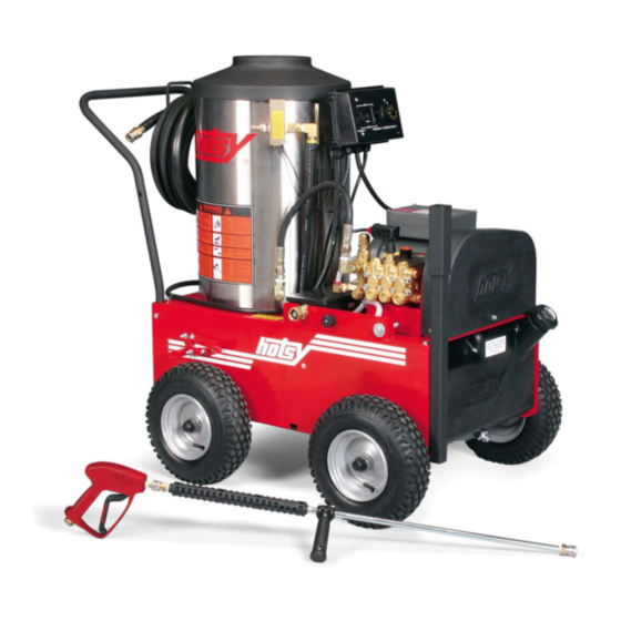
Page 7: Component Identification
IMPORTANT SAFETY INFORMATION Follow the maintenance instructions specified in the manual. COMPONENT IDENTIFICATION Adjustable Coil Thermostat Hose Reel Bracket Burner Switch Pump Switch Unloader Valve Pump Motor Fuel Oil Tank GFCI Detergent Line High Pressure Hose Spray Gun High Pressure Nozzle Wand Pump —... -
Page 8: Assembly Instructions
ASSEMBLY INSTRUCTIONS Unpacking gun assembly as shown in Figure 2. Handle Unpack carefully. Wear safety glasses or goggles while unpacking, assembling or operating pressure washer. If there are missing components or hidden damage Wand immediately contact distributor or carrier concerning Assembly discrepancies. -
Page 9: Installation Instructions
INSTALLATION INSTRUCTIONS Getting Started IMPORTANT: The use of a backflow preventer on the water supply hose is recommended and may be required by local code. The pressure washer should be run on a level surface where it is not readily influenced by outside sources such as strong winds, freezing temperatures, rain, etc. -
Page 10: Installation Instructions
INSTALLATION INSTRUCTIONS Burner Air Adjustment Crossfire Oil Burner The oil burner on this machine is preset for operation at Burner Air Adjustment: The oil burner on this machine altitudes below 500 feet. If operated at higher altitudes, is preset for operation at altitudes below 500 feet. If it may be necessary to adjust the air band for a #1 or operated at higher altitudes, it may be necessary to #2 smoke spot on the Bacharach scale. -
Page 11: Operation Instructions
2. Connect water supply hose to the standard garden hose connector. The water faucet and supply hose must be capable of providing 3.0 gpm for 790SS, and 4 gpm for 795SS, 795SS-208. 3. Fill fuel tank. Use kerosene, #1 grade home heating oil, #1 or #2 diesel fuel. -
Page 12: General Cleaning Techniques & Storage
GENERAL CLEANING TECHNIQUES & STORAGE RINSING CLEANING TECHNIQUES Pre-rinse cleaning surface with fresh water. Place de- It will take a few seconds for the detergent to clear. tergent suction tube directly into cleaning solution and Apply safety latch to spray gun. Select and install de- sired high pressure nozzle. -
Page 13: Maintenance
MAINTENANCE Pump Motor WARNING: Unauthorized machine modification or use of non-approved replacement parts may cause On a yearly basis, oil pump motor per instructions on personal injury and/or property damage and will void motor nameplate. the manufacturer warranty. Relief Valve Pump WARNING: The relief valve on this pressure washer Lubrication: To lubricate pump, use 30W non-detergent... -
Page 14: Troubleshooting
TROUBLESHOOTING SYMPTOM POSSIBLE CAUSES CORRECTIVE ACTION PUMP MOTOR WILL GFCI tripped. Reset and test GFCI with every use. Follow NOT RUN. Instructions under Operation. No voltage to machine. Test power supply and correct. Pump motor reset button (thermal Push reset button on control box. If tripped, overload protector) tripped. -
Page 15: Troubleshooting
IMPORTANT If the pressure washer demonstrates other symptoms or the corrective actions listed do not correct the problem, contact the local authorized Hotsy Service Center. The Hotsy Service Center can be identified by visiting www.hotsy.com. When ordering from your dealer, please provide the following:... -
Page 16: Exploded Views & Parts List
EXPLODED VIEW - LEFT SIDE Brake Assembly Detail See Coil Outlet Assy. Foot Brake Detail (Reversed View) Detail See Control Box Assy. Only 21,76 895SS To Float Tank Detergent Injector 895SS Only 8.914-355.0 • Rev. 07/17... - Page 17 EXPLODED VIEW - RIGHT SIDE Detail See Float Tank Assy. Detail See Brake Assy. Detail See Detergent Valve Assy. Detail See Detail See Burner Fuel Tank Assy. Assy. 8.914-355.0 • Rev. 07/17...
-
Page 18: Exploded View Parts List
Motor, 1725RPM 230V 1 Ph 1 9.803-098.0 Holder (790SS) 9.802-341.0 Motor, 3450RPM 230V 1 Ph 1 8.901-136.0 Label, Use Hotsy Detergent 1 (795SS) 9.803-845.0 Bolt, 1/2" x 5" Nc Hh Tap, 8.715-144.0 Motor, 3450RPM 200V 1 Ph 1 All Thread (795SS-208) 9.802-809.0... - Page 19 Bolt, 1/4-20 x 1/2", Nc Hh 8.706-577.0 Trim, Edge Guard, Blk/Ft 8.706-731.0 Bushing, 3/4" Snap 8.752-969.0 Strain Relief, 1/2 NPT (790SS Only) 9.802-518.0 Strain Relief, 3/4 Npt.49-.71D 1 (895SS, 795SS, 795SS-208) 9.802-767.0 Screw, 3/8" x 3/4" Nc, Whiz Loc Flange (895SS) 9.803-277.0...
-
Page 20: Control Panel Assembly & Parts List 790Ss & 795Ss
CONTROL PANEL ASSEMBLY, 790SS, 795SS, 795SS-208 16, 17 17, 16 CONTROL PANEL PARTS LIST ITEM PART NO. DESCRIPTION ITEM PART NO. DESCRIPTION 8.901-142.0 Label, Control Box 9.802-514.0 Strain Relief, 1/2 Npt, 8.716-053.0 Switch, Toggle, 40A/230V (795SS, 795SS-208, 790SS) 2 8.718-569.0 Screw, 10-32 x 1/2"... -
Page 21: Control Panel Assembly & Parts List 895Ss
CONTROL PANEL ASSEMBLY, 895SS CONTROL PANEL PARTS LIST ITEM PART NO. DESCRIPTION ITEM PART NO. DESCRIPTION 9.802-521.0 Strain Relief, Cg75-850, 3/4" 1 8.901-142.0 Label, Control Box 9.802-523.0 Locknut, 3/4" Conduit 8.716-053.0 Switch, Toggle, 40A/230V 9.802-434.0 Gfci, 240V 1 Ph 40A, 36' 8.718-569.0 Screw, 10-32 x 1/2"... -
Page 22: Burner Assembly & Parts List
1/8" - 5/16" 8.706-297.0 Bushing, 3/8" Steel Yellow 8.754-911.0 Check Valve, 1 way, Chrome 1/4" BARB 8.709-153.0 Filter, Fuel Hotsy, 3/8" Fem 1 8.717-711.0 ▲Screen Fuel Filter 8.706-965.0 Hose Barb, 9.802-649.0 ▲Blower Wheel 1/4" Barb x 3/8" ML Pipe, 9 8.750-520.0... -
Page 23: Fuel Tank Assembly & Parts List
FUEL TANK ASSEMBLY AND PARTS LIST ITEM PART NO. DESCRIPTION To Burner 8.706-614.0 Tank, Fuel, 8 Gal Hotsy Inlet 9.803-535.0 Cap With Fuel Display 14" 9.802-053.0 Bushing, Fuel Line, Rubber 2 9.802-141.0 Hose Barb, 1/4" Barb x 3/8" 1 Barb, Dou 9.802-254.0... -
Page 24: Pump Assembly & Parts List 790Ss & 795Ss
PUMP ASSEMBLY 790SS, 795SS PUMP PARTS LIST ITEM PART NO. DESCRIPTION ITEM PART NO. DESCRIPTION 8.705-173.0 Elbow, MPT (BR) 8.754-753.0 Pump, Leuco LB4025R, 1/2'M x 1/2M 4.0@2500, 1550RPM 8.706-947.0 Hose Barb 8.754-696.0 Unloader, VBT BANJO TO Male Pipe 1/2M 3/8M, 3000PSI 9.804-022.0... -
Page 25: Pump Assembly & Parts List 895Ss
ITEM PART NO. DESCRIPTION ITEM PART NO. DESCRIPTION 8.706-984.0 Adapter, 1/2" Fpt x 1/2" Mpt 1 8.751-179.0 Pump, Hotsy HM3540r.3, Brass 3.5@4000 1850 rpm 9.803-900.0 Unloader, (VBA)LM/LS 9.802-039.0 Elbow 1/2" JIC x 3/8" MPT 8.705-974.0 Nipple, 3/8" Hex Steel 8.706-207.0 Elbow, 3/8", Street 90 Deg... -
Page 26: Coil Outlet Assembly & Parts List
COIL OUTLET ASSEMBLY AND PARTS LIST ITEM PART NO. DESCRIPTION 9.149-003.0 Manifold Coil Outlet Discharge 8.706-241.0 Plug, 3/8", Sq Head, Galv 9.196-012.0 Screw, 10-24 x 1/4" Hex Set 1 9.802-041.0 Elbow, 3/8" Street 45 Dgr Steel 9.802-171.0 Coupler, 3/8" Plug, Male Steel / Zinc 8.902-433.0 Valve, Safety Relief Vsa... -
Page 27: Hose, Gun & Wand Assembly & Parts List
ITEM PART NO. DESCRIPTION 8.712-345.0 Nozzle, 0004 Red 8.916-740.0 Hose, 3/8" x 50', 1W, Ts, (790SS, 895SS) So x Sw ((All Except 895SS) 8.712-353.0 Nozzle, 0005 Red 8.739-183.0 Hose, 3/8" x 50', 2W, Tf, (795SS, 795SS-208) So x Sw (895SS) REPLACEMENT PARTS 8.712-346.0... -
Page 28: Pump - Exploded View & Parts List
PUMP - EXPLODED VIEW 8.754-753.0 HB4052R TORQUE SPECS Item # Ft.-lbs PUMP - EXPLODED VIEW PARTS LIST ITEM PART NO. DESCRIPTION 8.754-841.0 Crankcase 8.754-846.0 O-ring Ø1.78 X 72.75 See Kits Below Plunger Oil Seal See Kits Below O-ring Ø1.78 X 26.7 See Kits Below Washer, Pressure Ring 16 mm See Kits Below U-Seal, 16 mm See Kits Below Pressure Ring, 16 mm... -
Page 29: Pump - Exploded View & Parts List
PUMP - EXPLODED VIEW PARTS LIST ITEM PART NO. DESCRIPTION 8.717-137.0 Bearing Cover 9.803-954.0 Bearing Seal 8.754-843.0 Seal Spacer, Crankshaft 9.802-914.0 Snap Ring, 25 mm 9.803-955.0 Bearing, Ball 8.754-830.0 Shaft, 24 mm 4025 9.803-167.0 Key, Crankshaft 8.754-219.0 Oil Dipstick 8.933-010.0 Seal, Crankshaft 8.754-855.0 Bolt, Plunger... -
Page 30: Mt Pump - Exploded View & Parts List
HM PUMP EXPLODED VIEW - PUMP PARTS LIST TORQUE SPECS Item # Ft.-lbs HM PUMP - EXPLODED VIEW PARTS LIST ITEM PART NO. DESCRIPTION 9.803-178.0 Shim 8.751-216.0 Crankcase 8.717-209.0 Bearing Housing See Kits Below Plunger Oil Seal See Kits Below Plunger Nut, M8 See Kits Below O-Ring, 1.78 X 31.47 See Kits Below Copper Spacer See Kits Below Pressure Ring... - Page 31 HM PUMP EXPLODED VIEW - PUMP PARTS LIST CONT. REPAIR KIT NO. 8.725-360.0 8.725-362.0 8.725-358.0 8.725-361.0 8.725-363.0 8.725-359.0 8.751-237.0 8.751-238.0 8.933-023.0 9.802-603.0 9.802-609.0 Complete Complete Complete Seal Seal Seal Plunger Seal Plunger Seal Plunger Seal Packing Packing Packing Plunger Plunger Plunger 4035 4030, 4031...
-
Page 32: Burner Hotsy Crossfire Exploded View And Part List
WAYNE BURNER EXPLODED VIEW Replacement Parts For best performance specify genuine replacement parts 8.914-355.0 • Rev. 07/17... -
Page 33: Replacement Parts
WAYNE BURNER PART LIST Replacement Parts For best performance specify genuine KNA replacement parts ITEM PART NO. DESCRIPTION 101396-002 Tube/Hous-21922-001/7A/3.75"/.88"I 101391-002 Ignitor-D W/M Plate 230V 100990-001 Spring, Contact 21319-002 J-Box,3" x 4" M/F 21319 20601-002 Band, Air Inner-Mod-M 20602-002 Band, Air Outer 8-Hole Mod-M 13392 Plate, Slot Cover 30537-028... -
Page 34: Vba Unloader Exploded View And Parts List
VBA UNLOADER EXPLODED VIEW 8.715-491.0 5-3303 #921460 8.715-490.0 5-3300 #921465 VBA UNLOADER EXPLODED VIEW PARTS LIST ITEM PART NO. DESCRIPTION ITEM PART NO. DESCRIPTION Body Valve (KG) Poppet Body Valve (KS) 9.802-893.0 Seal Washer 3/8 O-Ring 9.803-915.0 Banjo Bolt 3/8" w 1/8" Pilot Seat 9.803-919.0 Banjo Bolt 3/8"... -
Page 35: Wiring Diagram
VBT UNLOADER EXPLODED VIEW 8.754-696.0 Unloader, VBT Banjo 1/2M 3/8M, 3000PSI (SPARE) VBT UNLOADER EXPLODED VIEW PARTS LIST ITEM PART # DESCRIPTION KIT QTY ITEM PART # DESCRIPTION KIT QTY 8.754-929.0 Stem 9.803-914.0 Seal Washer 1/2) 9.803-912.0 Backup Ring 8.754-937.0 Bypass Manifold 8.754-930.0 O-ring, Ø2.62 x 6.02 9.802-892.0 Outlet Connector 3/8 MPT 8.730-882.0 Stem Connector... - Page 36 WIRING DIAGRAM- 790SS, 795SS 8.914-355.0 • Rev. 07/17...
- Page 37 WIRING DIAGRAM- 895SS 8.914-355.0 • Rev. 07/17...
- Page 39 If you need SERVICE on your pressure washer, contact your local Hotsy dealer or visit www.Hotsy.com. Smart phone users scan the code below to link directly to the Service Request page. To REGISTER your pressure washer, please visit our Warranty Registra- tion page at www.hotsy.com/WarrantyRegistration.aspx or scan the code...
Need help?
Do you have a question about the 790SS and is the answer not in the manual?
Questions and answers