Advertisement
its Space. its Budget
Approx. 30 minutes
Recomm. 2 Person
Tool Required
Tool Required
Customer Support
NEED HELP? For help with assembly, or if you are missing a
part, please call Furinno Customer Service, 1-773-299-8111
from Mon-Fri, 9am-5pm (CST) or email: support@furinno.com
www.furinno.com
STEP 1
Insert Mini Fix Cam (3) to Panel (A&B), as shown.
STEP 2
2.1 Install L Bracket (7) to Bar (D) with Small Screw (2).
2.2 Attach assembled unit to Panel (B) with Small Screw (2).
Assembly Instruction
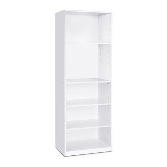
Furinno 5 Tier Shelf Bookcase
14110R1
MODEL
:
DIMENSION :
24.5"(W) x 71.2"(H) x 9.5"(D)
14110R120151111
No
Hardware List
Large Screw
1
2pcs
2
Small Screw
4pcs
3
Mini Fix Cam
12pcs
4
Mini Fix Bolt
12pcs
5
Power Pin
46pcs
6
Shelving Support
12pcs
7
L Bracket
2pcs
Wall Mounting Set
8
2sets
STEP 3
3.1 Insert Mini Fix Bolt (4) into Panel (I) using screwdriver.
3.2 Attach Panel (I) to assembled unit in Step 2, as shown.
STEP 4
Insert Mini Fix Bolt (4) into Panel (H) and attach Panel (H) to Panel (B), as shown.
Qty
No
Parts List
Top Panel
A
Bottom Panel
B
C
Shelf Panel
D
Bottom Bar
E
Center Panel
F
Top Left Side Panel
Top Right Side Panel
G
Bottom Left Side Panel
H
I
Bottom Right Side Panel
J
Bottom Back Panel
Top Back Panel
K
Qty
1pc
1pc
3pcs
1pc
1pc
1pc
1pc
1pc
1pc
1set
1set
Advertisement
Table of Contents

Related Manuals for Furinno 14110R1


Summary of Contents for Furinno 14110R1
- Page 1 Recomm. 2 Person Tool Required Tool Required Customer Support NEED HELP? For help with assembly, or if you are missing a part, please call Furinno Customer Service, 1-773-299-8111 from Mon-Fri, 9am-5pm (CST) or email: support@furinno.com www.furinno.com 14110R120151111 STEP 3 STEP 1 3.1 Insert Mini Fix Bolt (4) into Panel (I) using screwdriver.
- Page 2 STEP 5 STEP 7 Insert Mini Fix Bolt (4) to Panel (G) and attach Panel (G) to Panel (A), as shown. Combine both assembled unit in Step (4&6), as shown. STEP 6 STEP 8 6.1 Insert Mini Fix Bolt (4) to Panel (E&F). Attach Back Panel (J&K) to the back of the assembled unit using Power Pin (5).
Need help?
Do you have a question about the 14110R1 and is the answer not in the manual?
Questions and answers