Sign In
Upload
Download
Table of Contents
Contents
Add to my manuals
Delete from my manuals
Share
URL of this page:
HTML Link:
Bookmark this page
Add
Manual will be automatically added to "My Manuals"
Print this page
×
Bookmark added
×
Added to my manuals
Manuals
Brands
Bosch Manuals
Temperature Controller
8733951033
Installation & operation manual
Bosch 8733951033 Installation & Operation Manual
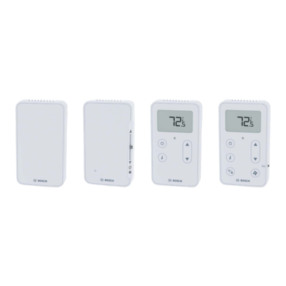
Zs series zone sensors r1 compatible with ddc control air 5600, 5830, and 6120 controllers
Hide thumbs
1
2
Table Of Contents
3
4
5
6
7
8
9
10
11
12
13
14
15
16
17
18
19
20
21
22
23
24
page
of
24
Go
/
24
Contents
Table of Contents
Troubleshooting
Bookmarks
Table of Contents
Table of Contents
1 Key to Symbols and Safety Instructions
Key to Symbols
Safety
2 Overview
3 Available Models
4 Specifi Cations
5 Features
6 Addressing Sensors
7 Multiple Sensors
8 Formatting Sensors
9 ZS Push/Manager Sensors
Navigating the Push/Manager Sensor's Screens
ZS Push Sensor Display
To Make the Zone Warmer or Cooler Using a ZS Push/Manager
To Override the Schedule Using a ZS Push/Manager
To Lock the Sensor Buttons of a ZS Push/Manager
To Edit Displayed Values Using a ZS Push/Manager
Rnet Tags
10 Troubleshooting
Battery Reset
11 Wiring and Mounting
12 ZS Series Zone Sensor R1 Dimensions
13 Compatible Controllers
14 Electrical Schematic
15 Terminology
16 Common Abbreviations
17 Control Signals
Advertisement
Quick Links
1
Key to Symbols and Safety Instructions
2
Overview
3
Available Models
4
Features
5
Navigating the Push/Manager Sensor's Screens
6
Troubleshooting
7
Wiring and Mounting
Download this manual
Bosch ZS Series Zone Sensors R1
Compatible with DDC Control Air 5600, 5830, and 6120 Controllers
Installation & Operation Manual
Table of
Contents
Previous
Page
Next
Page
1
2
3
4
5
Advertisement
Table of Contents
Need help?
Do you have a question about the 8733951033 and is the answer not in the manual?
Ask a question
Questions and answers
Related Manuals for Bosch 8733951033
Temperature Controller Bosch C1210ES Technical Service Bulletin
Checking and replacing temperature sensors (2 pages)
Temperature Controller Bosch FR 100 Installation And Operating Manual
Room temperature controller with solar control (88 pages)
Temperature Controller Bosch FW 100 Operating Instructions Manual
Weather-compensated controller with solar control (40 pages)
Temperature Controller Bosch FR 120 Operating Instructions For The User
Room temperature controller with solar control (36 pages)
Temperature Controller Bosch EMS plus MM100 Installation Instructions Manual
Skilled labour (104 pages)
Temperature Controller Bosch HEZ39050 Instruction Manual
Wireless temperature sensor (140 pages)
Temperature Controller Bosch YPRM66XB Operation Handbook
(13 pages)
Temperature Controller Bosch CRC200 Installation Instructions For Contractors
Comfort room controller (32 pages)
Temperature Controller Bosch HEZ39050 Instruction Manual
Wireless temperature sensor (164 pages)
Temperature Controller Bosch Junkers NTC 10K Manual
(56 pages)
Temperature Controller Bosch FR 120 Installation And Operating Instructions Manual
Room temperature controller with solar control (68 pages)
Temperature Controller Bosch CLIMO A D00 A40 103 Manual
Micro climate monitoring system (18 pages)
Temperature Controller Bosch FB 100 Operating Instructions Manual
Remote control and room sensor (32 pages)
This manual is also suitable for:
Zs-1
8733951034
Zs-1h
Zs-1s
8733951035
Zsp-1
...
Show all
8733951036
Zsp-1h
8733951037
Zsp-1hc
Zsm-1
8733951039
8733951038
Zsm-1h
8733951040
Zsm-1hc
8733951041
Table of Contents
Print
Rename the bookmark
Delete bookmark?
Delete from my manuals?
Login
Sign In
OR
Sign in with Facebook
Sign in with Google
Upload manual
Upload from disk
Upload from URL


Need help?
Do you have a question about the 8733951033 and is the answer not in the manual?
Questions and answers