
Related Manuals for Cornelius SPIRE 4.1


Summary of Contents for Cornelius SPIRE 4.1
- Page 1 SPIRE 4.1 Installation Manual Release Date: September 18, 2017 Publication Number: 620066826INS Revision Date: December 18, 2017 Revision: B...
-
Page 2: Contact Information
Commercial Warranty. Cornelius will not be responsible for any repair, replacement or other service required by or loss or damage resulting from any of the following occurrences, including but not limited to, (1) other than normal and proper use and normal... -
Page 3: Table Of Contents
Marking and Cutting the Counter - Spire 4.1 ....... . . - Page 4 Service Mode - Service Screen ........... 24 Mapping the Valves .
-
Page 5: Safety Instructions
Spire 4.1 Installation Manual SAFETY INSTRUCTIONS AFETY VERVIEW • Read and follow ALL SAFETY INSTRUCTIONS in this manual and any warning/caution labels on the unit (decals, labels or laminated cards). • Read and understand ALL applicable OSHA (Occupational Safety and Health Administration) safety regulations before operating this unit. -
Page 6: Safety Precautions
Spire 4.1 Installation Manual AFETY RECAUTIONS This unit has been specifically designed to provide protection against personal injury. To ensure continued protection observe the following: Disconnect power to the unit before servicing following all lock out/tag out procedures established by the user. Verify all the power is off to the unit before any work is performed. Failure to disconnect WARNING the power could result in serious injury, death or equipment damage. -
Page 7: Spire 4.1 System Overview
4.1: D PIRE ESCRIPTION Spire 4.1 solves your ice and beverage service needs in a sanitary, space saving, economical way. It is designed to manually fill with ice from any remote ice-making source. The unit includes the following components: •... -
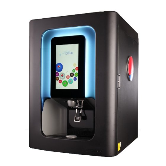
Page 8: Spire 4.1: Physical Dimensions
Spire 4.1 Installation Manual 4.1: P PIRE HYSICAL IMENSIONS Figure 1. Spire 4.1 Physical Dimensions Publication Number: 620066826INS - 8 - © 2017, Cornelius Inc. -
Page 9: Delivery, Inspection & Unpacking
ELIVERY AND NSPECTION NOTE: Cornelius is not responsible for damaged freight. If damage is found, you must save all packaging material and contact the freight carrier. Failure to contact the carrier within 48 hours of receipt may void your claim. -
Page 10: Preparing The Counter
Spire 4.1 Installation Manual PREPARING THE COUNTER To place the Spire 4.1 unit on a counter, the counter must be prepared by cutting a slot in the counter to accommo- date the syrup lines and power cord connection to the unit. -
Page 11: Sanitizing The Ice Bin
Spire 4.1 Installation Manual ANITIZING THE It is easier to sanitize the ice bin before placing the unit on the counter. This procedure can be performed after posi- tioning the unit on the counter, if desired. Perform the following steps to sanitize the ice bin:... - Page 12 Spire 4.1 Installation Manual Bottom Agitator over the spindle 5. Place the bottom agitator over the spindle as shown in Figure 7. Figure 7 Top and Bottom Agitator Assembly 6. Then, place the top agitator in place over the bottom agita- tor making sure the two agitator components are seated properly as shown in Figure 8.
-
Page 13: Positioning The Spire Dispenser On The Counter
Spire 4.1 Installation Manual OSITIONING THE PIRE ISPENSER N THE OUNTER The Spire unit is very heavy and extreme care should be taken when moving or lifting the unit. Do not attempt to lift the unit manually. Failure to comply could result in serious injury, death or damage to the equipment. -
Page 14: Ice Maker Mounting
Make sure Ice flow from the dispenser ice chute is sufficient for ice type. (See “Ice Chute Restrictor Adjustment” on page 36). • Note that if chew-able ice is used, additional parts and components must be ordered from Cornelius. Publication Number: 620066826INS - 14 -... -
Page 15: Connecting The Unit
Spire 4.1 Installation Manual CONNECTING THE UNIT EMOVING THE NCLAVE The Enclave provides access to service lines to support installing and servicing water, CO syrup and drain lines. Read all steps first, then, perform the following steps to remove and replace the Enclave. -
Page 16: Replacing The Enclave
Spire 4.1 Installation Manual 4. With each Enclave tab released from a tab hold- ers, guide the Enclave forward and out of the unit. Place it in a safe place. Result: The Enclave is removed from the unit and the service lines are exposed to support installation and service activities. -
Page 17: Installing Water, Co2 And Syrup Lines
Spire 4.1 Installation Manual , CO NSTALLING ATER 2 AND YRUP INES Once the unit is located in its final position on the counter, the unit must be plumbed by connecting the supply lines (water, CO and syrup lines). Perform the procedure below to plumb the unit. -
Page 18: Installing The Drain
Spire 4.1 Installation Manual NSTALLING THE RAIN After installing the syrup, water and CO lines, the drain lines must be installed. Perform the following steps to install the drain line: 1. Pull the drain tube stub from the storage space in the bottom of the unit and route it through the cut-out in the counter. -
Page 19: Filling The Ice Bin (Manual)
Spire 4.1 Installation Manual ILLING THE ANUAL For an Ice Maker equipped unit, refer to the ice maker manufacturer's manual to begin filling the ice hopper with ice. The dispenser cannot be used with crushed or flaked ice. Use of bagged ice which has frozen into large chunks can void warranty. -
Page 20: Initial Setup
On the Spire 4.1 unit, the carbonator tank relief valve is located to the right of the agitator motor on the far right side of the unit. To open the Tank valve, pull on the valve ring. - Page 21 Spire 4.1 Installation Manual Pressure Gauge 5. Verify that the pressure gauge on the cylinder reads over 110 PSI. Figure 27 6. Plug the Spire unit into an AC power source. This supplies power to the Spire unit. NOTE: After AC power is supplied to the Spire unit, power is also supplied to the carbonator pump deck assembly as long as the dedicated power cord from the Spire unit was routed and connected to the electri- cal junction box or other connection providing power to the pump.
-
Page 22: Accessing The Service Menu And Service Mode
Spire 4.1 Installation Manual CCESSING ERVICE ENU AND ERVICE The unit provides a service mode feature to allow service personnel access to a set of service menu items used to setup and service the dispenser. Perform the following steps to access the Service Menu and place the unit in Service Mode: 1. -
Page 23: Service Mode - Initial Setup
Spire 4.1 Installation Manual ERVICE NITIAL ETUP The initial setup process establishes various configuration parameters for the unit. Review the following, and all steps in the process, before performing Initial Setup. • After entering a PIN on the Enter PIN screen to put the unit in Service Mode, if configuration parameters need to be provided to the unit, the EDIT SPIRE FIRST TIME SETUP SETTINGS screens appear to prompt the user through an Initial Setup process. -
Page 24: Service Mode - Service Screen
Spire 4.1 Installation Manual ERVICE ERVICE CREEN After Initial Setup, the Service button on the Service Menu will display the Service screen as described below and shown in Figure 34 Figure 34 Service Screen Interface The Service screen contains icons categorized in the three sections, described below. Note that screens for your unit may be slightly different than screens shown in example figures provided here. -
Page 25: Mapping The Valves
Spire 4.1 Installation Manual APPING THE ALVES Mapping the valves is the process where icons on the display screen are assigned to the valves associated with plumbed lines matching a brand or product to be dispensed. To simplify the mapping process, make sure each plumbed line is labeled appropriately to represent the brand or product for each valve. - Page 26 Spire 4.1 Installation Manual 5. Repeat steps 1 through 4 to assign (map) the following valves: • Map PW-R-V2 to High Still • Map CW-L-V3 to Low Carb • Map PW-L-V4 to Low Still Result: Valves 1 through 4 are assigned (mapped) to High Carb, High Still, Low Carb, Low Still, respectively as in Figure 39.
-
Page 27: Changing Valve Assignments
Spire 4.1 Installation Manual HANGING ALVE SSIGNMENTS After establishing valve assignments to map brand icons to valves, changes can be made to map a brand icons to dif- ferent valves associated with a different brand or product to be dispensed. -
Page 28: Priming Lines
Spire 4.1 Installation Manual RIMING INES Priming a line can be done individually or up to five (5) lines can be purged simultaneously. Read all the information and activity steps before priming the lines. To prime an individual line, see “Priming Individual Lines” on page 28. -
Page 29: Priming Multiple Lines
Spire 4.1 Installation Manual 5. Make sure the correct water is being dispensed (Carb or Plain depending on the valve selected). Then, press the Stop Prime Dispense button. Result: The flow stops and the Current Assignment screen for the valve appears. - Page 30 Spire 4.1 Installation Manual 3. With the valve icons identified as Selected, start the prime function. To do this, press the Start button. Result: The prime function starts for the valve lines selected and the Stop button appears at the bottom of the screen.
-
Page 31: Adjust Water To Syrup Ratio (Brix)
Spire 4.1 Installation Manual (BRIX) DJUST ATER TO YRUP ATIO The BRIX process adjusts the water to syrup ratio for a brand or flavor. Read all and steps before conducting the pro- cedure. • Lines must be purged prior to brixing. - Page 32 Spire 4.1 Installation Manual 6. From the BRIX Calibration screen, select BRIX Dis- pense. Result: The brixing process starts and a Calibrating icon appears on the BRIX Calibration screen. Figure 53 7. During the brixing process, you may need to adjust the flow of the valve selected. To adjust the flow of a valve, do the following: To increase the flow of a valve, turn the valve clockwise.
-
Page 33: Viewing Valve Layout
Spire 4.1 Installation Manual IEWING ALVE AYOUT To support service operations, the unit can provide a view of the valve layout and assignments. Note that screens for your unit may be slightly different than screens shown in example figures provided here. -
Page 34: Viewing Defined Flow Rates
Spire 4.1 Installation Manual IEWING EFINED ATES Perform the following steps to view the defined flow rates. 1. Enter Service Mode and access the Service Screen. See “Accessing The Service Menu and Service Mode” on page 22. 2. From the Service Screen, in the Actions section, select the Define Flow Rates icon. -
Page 35: Off-Cycle Agitator Settings
Spire 4.1 Installation Manual YCLE GITATOR ETTINGS It is important to correctly set the ON/OFF times for off-cycle ice agitation to prevent ice dispense and storage issues. The default factory timer settings are set at 4 seconds ON / 1 hour OFF. It may be necessary to adjust these times based on ice type and quality used with this dispenser. -
Page 36: Ice Chute Restrictor Adjustment
Spire 4.1 Installation Manual HUTE ESTRICTOR DJUSTMENT To adjust ice flow rate out of the ice chute, it may be necessary to increase or decrease flow rate based on customer use and/or ice type. The default factory ice opening is 1.5”. -
Page 37: Diagrams
Spire 4.1 Installation Manual DIAGRAMS Figure 60 © 2017, Cornelius Inc. - 37 - Publication Number: 620066826INS... - Page 38 Spire 4.1 Installation Manual Figure 61 Publication Number: 620066826INS - 38 - © 2017, Cornelius Inc.
-
Page 39: Troubleshooting
Spire 4.1 Installation Manual TROUBLESHOOTING NOTE:Refer to the electrical and flow diagrams located inside of the E-Box cover for troubleshooting. CAUTION: Only qualified personnel should service internal components or electrical wiring. WARNING: If repairs are to be made to a product system, remove quick disconnects from the applicable product tank, then relieve the system pressure before proceeding. - Page 40 Spire 4.1 Installation Manual Valve brix requires adjustment Adjust valve brix Carbonator is not operating Repair carbonator Beverage is too sweet No CO in carbonator Restore CO pressure in carbonator Booster pump must be used if dynamic water City water pressure supply low or inconsistent pressure drops below 40 psig.
-
Page 41: Diagnostics Guide For Agitator Timer Board
Spire 4.1 Installation Manual Poor electrical connections between carbon- Check connections at carbonator tank and at ator tank and main control board connector J4 on the main control board. Carbonator tank over- fills, overflows through Broken wires between carbonator tank and... - Page 42 Spire 4.1 Installation Manual Publication Number: 620066826INS - 42 - © 2017, Cornelius Inc.
- Page 44 Cornelius Inc. www.cornelius.com...
Need help?
Do you have a question about the SPIRE 4.1 and is the answer not in the manual?
Questions and answers
How to connect usb and change drink flavor icon