Table of Contents
Advertisement
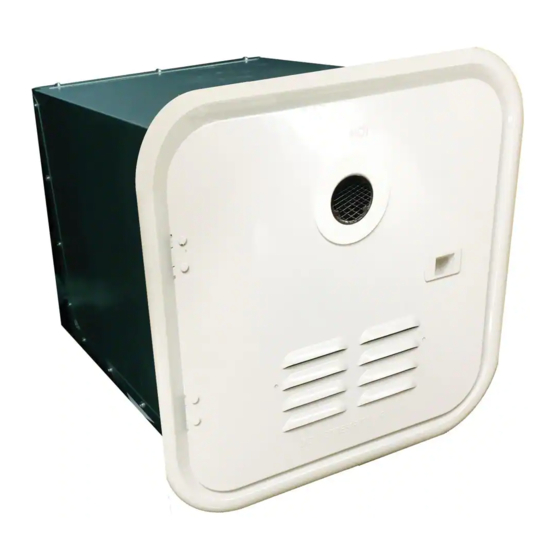
Technical Manual
Model: GSWH-2
Features:
• Demand Tankless Water Heater
• LP Gas / Induced Draft
• Constant Outlet Temperature
• Linear Gas Control Valve
• Electronic Gas Modulation
• Microprocessor Controls
Operation
Functional Tests
Troubleshooting
Service and Maintenance
Service must be performed by a
certified installer, service agency
or gas supplier.
This water heater is certified for
installation in Recreation Vehicles
(RV's) and is not for use in Marine
or Space Heating Applications
Girard Products LLC, 1361 Calle Avanzado, San Clemente CA 92673 USA
For service and spare parts:
Girard Products LLC
2515 Lombardy Dr.
Goshen, IN 46526
866-559-1221
.
Patent Pending
1
Advertisement
Table of Contents
Troubleshooting

Related Manuals for Girard Products GSWH-2


Summary of Contents for Girard Products GSWH-2
-
Page 1: Troubleshooting
2515 Lombardy Dr. Goshen, IN 46526 866-559-1221 This water heater is certified for installation in Recreation Vehicles (RV’s) and is not for use in Marine or Space Heating Applications Girard Products LLC, 1361 Calle Avanzado, San Clemente CA 92673 USA Patent Pending... - Page 2 TANKLESS WATER HEATER - Model GSWH-2 CONSUMER SAFETY WARNING! • Use with Universal LPG only. • Shut off all gas appliances and pilot lights when refueling. • Turn gas OFF at the LP tank when vehicle is in motion. This disables all gas appliances and pilot lights.
- Page 3 The Girard Products model GSWH-2 introduces a new generation of smart tankless water heater designed specifically for Recreation Vehicles (RV). Its configuration and size are consistent with the tank based RV water heaters currently in use and is designed for OEM’s and after-market use by the RV Industry.
- Page 4 It is dangerous to operate a Tankless Water Heater unattended. This may occur accidentally if a sufficient leak develops in the water system or if a faucet is left open. For this reason, The GSWH-2 will automatically turn off after operating for 20 minutes and displays Error “En” on the Display.
-
Page 5: Sequence Of Operation
Troubleshooting & Repair Guide Sequence of Operation a. Tools required: 1. Multi-meter 4. Thermocouple readout or Thermometer 2. Gas pressure manometer 5. Wrenches (23MM, 19MM, 15MM) 3. Screwdrivers (Slot and Phillips heads) 6. Pliers (Regular and Needle Nose) b. Installation verification: en the door and verify that: There is no obstruction to the air flow within the housing (Objects, dirt or other) The Exhaust tube is free and clear of any obstruction (Leafs, insect nests, other) - Page 6 Static Operation – No Water Flow Input 12VDC Power: Red wire positive and black wire ground to back of the water heater Confirm that you have a good power source with filtered voltage. Older linear type converters can cause issues with the operation of this more advanced board.
- Page 7 Pull Wires through cut out. Note: Wires are soldered to switch Loosen 15 mm nut on the fuse. Pull fuse forward and then pull wires through the cut out. Power wire connector for incoming 12VDC to the Board Operational Indicator LED’s These LED’s indicate proper voltage and operation of the water heater.
-
Page 8: User Control Panel
User control panel Recommended Setting 115 degrees. Icons showing temperature setting, Output Temperature, Fan, Flame and Water Flow. These are important to troubleshooting. Confirm that you can change the temperature setting on the UCP. Wire connections. ... -
Page 9: Water Flow Sensor
Hot water flow on - Pre-Trial for Ignition Water Flow Sensor: As the water flow increases the board will increase the BTU’s to compensate for the lower temperature rise. As the water flow decreases the board will decrease the BTU’s to compensate for the higher temperature rise. The water flow sensor or water flow meter gives the actual water flow measurement to the control board. -
Page 10: Voltage Test
Mixing of hot and cold water will restrict the water flow through the water heater. When mixing hot and cold water at the faucet you will start to diminish the flow through the water heater. When the flow is low enough the board will no longer sense that there is enough flow of water and the board will turn off the operation of the water heater. - Page 11 Removal and Replacement of the Flow Meter Remove the set screw on the front of the flow meter. Loosen the compression fitting on the top of the flow meter using a 5/16” or a 23mm wrench. Twist the flow meter plumbing and pull the flow meter upward.
- Page 12 Once the board senses water flow then the board will read the ECO to ensure it is not open. The wire connections on the ECO are clip type spade connections. Pull back the insulation over the spade connection and push the clip down and pull simultaneously. If the ECO is tested open by the control board when the hot water faucet is turned on then the control panel will show the water flow symbol and an E3 fault.
- Page 13 If the temperature of the water displayed at the UCP is nowhere near the temperature of the water coming out of the water heater you may have a thermistor out of calibration. Check the temperature on the copper pipe where the output thermistor is located with a laser thermometer to confirm the temperature.
- Page 14 Blower Motor Operation This water heater is equipped with a 4 wire variable speed brushless motor. The motor operates with a 24VDC pulse width modulation system. Which means there is Voltage at all 4 wires on the CN1 plug with or without the motor running. When the hot water faucet is turned on the water flow symbol (showerhead) will turn on at the UCP.
-
Page 15: Pressure Switch
Pressure Switch The pressure switch is the air proving device on the water heater. It is vital that the fan is operating before the board goes into ignition mode. The pressure switch contacts close as the air from the fan passes over the Petit Tube inside the blower housing. This creates a suction on the hose that connects the fan housing to the pressure switch. -
Page 16: Control Board
Trial for ignition Control Board Once the board senses the water flow meter, ECO, Thermistor, Motor Operation and Pressure switch activation then the board will power the gas valve and send high voltage for the spark. This is a two try board. If there is no ignition then you will get an E1 fault code and you will need to perform a soft reset by turning the water flow off and then back on again. - Page 17 Girard GSWH-2: E-1 Code/Gas Valve Trouble-Shooting and R&R The E1 fault code tells you that the water heater tried to ignite twice but did not ignite. An E1 fault code is not always caused by a failure of the gas valve to open. Additional diagnosis needs to be performed since this fault code may be caused by a number of issues.
- Page 18 5. Check voltage between the brown and the black wires during the Gas Valve trial for ignition. You should have 12VDC Output Test Port 6. The resistance on the coil should be approximately 110 ohms. 7. The output gas pressure of the gas valve can be measured at the test port on the right side of the board.
- Page 19 Vent Do not attempt to repair gas valves. If an E7 fault code appears then the board is not sensing the linear valve. If this occurs, then you will need to check the connection of the white and red wires on the 8 wire plug as well as the connections behind the firewall. The resistance of the coil of the linear valve can be measured at the white and red wires of 8 wire connector when it is unplugged.
- Page 20 Top tab 15mm showing Disconnect red and black wire Pull forward connector and through the Cut Out 5. Pull the fuse holder out and the wires through the cut out. 6. Disconnect the input power connector and pull it through the board panel. High Voltage Wires and Connections...
- Page 21 8. Remove the Philips screws secure the fire wall to the blower housing, gas valve bracket, ground, gas test port and bottom case. Remove 2 Top Screws Remove 2 valve bracket screws and the 1 case screw Remove 1 screw from the case, 1 screw for ground and 1 screw for the gas pressure test port...
- Page 22 10. Remove the gas line from the orifice block using a 19 mm or 3/4 inch wrench. 11. Remove the gas line from the water heater and cover to prevent damage. Warning: Do not over overtighten gas connection when reattaching it to the orifice block 12.
-
Page 23: Gas Valve Assembly
Gas Valve Assembly Once removed 14. Remove the output gas line from the gas valve. Note the position of the O Ring. Loosen the set screws that hold the gas line place. 15. Remove the set screws that hold the input gas line in place. - Page 24 Orifice Block: The orifice block is located under the burner. It has 6 orifices metering gas into the burners. Three to the left and three to the right. Debris in the orifices can cause poor flame quality and can cause insufficient temperature rise. Removal and replacement: Remove Gas line 19mm or ¾”...
-
Page 25: Burner Assembly
Burner Assembly Removal and replacement Bracket - Catch Once the orifice block is removed the only thing holding the burner assembly in is the bracket in the catch Reach into the back under the burner and bend the bracket to about a 45 degree angle and pull the burner bracket out of the catch. -
Page 26: Flame Sense
Flame sense The flame sense probe is the right hand post of the igniter assembly which wires into the red wire on the board. There is a 7 second trial for ignition. Once the flame is lit and on the flame sense probe it should take a second for the control board to recognize the flame. - Page 27 Freezing water inside of the heat exchanger (just like a tank water heater) will expand and cause a bulging crack on one of the copper tubes of the heat exchanger. Winterization can be accomplished using on the two common methods of winterization used for RV systems.
-
Page 28: Faqs And Troubleshooting
FAQ’s and Troubleshooting The new GSWH-2 water heater differs from its predecessors in that it allows the customer to operate the product just as they would a regular tank water heater. By this we mean that they simply turn on the hot side and add cold water to their desired temperature. - Page 29 Smell for gas coming out of the exhaust. If the weather is cold, do they have enough propane in the tank? Is the regulator on the tank working? Replace gas valve. Water heater comes on and immediately gives an E-5 code (motor failure). ...
- Page 30 Malfunction 1: Unit does not attempt to light when water is turned on Error codes: E0, E3, E4, E5, E7, E8, E9 Procedure: If any of the above Error codes are displayed proceed as follows: E0 - Verify connections to the Probe. Verify with a Voltmeter that the resistance of the outlet probe is not an open circuit or a short. If it is install a new Probe.
- Page 31 Error Codes on User Control Panel E0: Water Outlet Temperature Probe failure. An open circuit or short circuit condition is detected: This could be due to an internal failure in the Temperature Probe or to a faulty connection (Wires) E1: Ignition failure or accidental flame off during ignition. If the established flame signal is lost while the burner is operating, the control will respond within 0.8 seconds, the gas valve is de-energized and a new inter-purge and ignition routine will begin.
-
Page 32: Exploded View
Exploded View... - Page 33 Replacement Parts: Components Description Photo Qty. Description Photo Pressure Relief Valve Shell Top Direction Tube Proportional Pressure Valve (Gas Valve) Relief Valve Valve Water Pipe Bracket Assembly Power switch & Fuse Flow Switch Inlet holder Assy External Fuse10A Filter Screen Inlet Controller Dust Cap: Bracket...
-
Page 34: Functional Diagram
Functional Diagram Wire Diagram... - Page 35 Operational failure caused by improper installation or the use of non GSWH-2 components will result in the warranty claim being denied. All warranty parts in the first year of warranty will be ship FedEx ground. Contact Girard Products Customer Service with questions or concerns about labor hour’s guidelines or labor functions (949) 259-4024.
- Page 36 [Type here] [Type here]...