Table of Contents
Advertisement
Sigma Air Conditioning NYC
is proud to be have been servicing the Greater New York City area for over
25 years. Our team of experts is here to work with you to meet all your air conditioning needs. We
provide air conditioning service, sales, and will install your new air conditioning if you require it.
212.686.3121
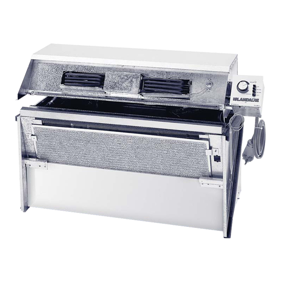
Islandaire Manual Model # EZ Series 25
Advertisement
Table of Contents

Related Manuals for Islandaire EZ Series 25


Summary of Contents for Islandaire EZ Series 25
- Page 1 25 years. Our team of experts is here to work with you to meet all your air conditioning needs. We provide air conditioning service, sales, and will install your new air conditioning if you require it. 212.686.3121 Islandaire Manual Model # EZ Series 25...
- Page 2 Operating & Maintenance Manual for Islandaire Packaged Terminal Thru-Wall Air Conditioners & Heat Pumps *THIS BOOK CONTAINS INFORMATION ON THE OPERATION OF YOUR UNIT. KEEP IN A SAFE PLACE FOR READY REFERENCE. SHOULD YOU REQUIRE ANY FURTHER INFORMATION, CONTACT YOUR DEALER OR...
- Page 3 OUR TECHNICAL SUPPORT DEPARTMENT AT 1-800-886-2759. THE INFORMATION IN THIS MANUAL MUST BE FOLLOWED. IMPROPER INSTALLATION, ADJUSTMENT, ALTERATION, SERVICE, OR MAINTENANCE CAN VOID WARRANTY, CAUSE PROPERTY DAMAGE, PERSONAL INJURY, OR LOSS OF LIFE. A QUALIFIED INSTALLER OR SERVICE AGENCY MUST PERFORM INSTALLATION OR SERVICE. ALL LOCAL AND NATIONAL CODES MUST BE ADHERED TO WHEN INSTALLING THIS PRODUCT! TO MAINTAIN WARRANTY COVERAGE THE CONDENSER COIL SURFACE MUST BE CLEANED REGULARLY, AND THE ROOM AIR FILTER MUST BE CLEANED REGULARLY.
-
Page 4: Table Of Contents
Table of Contents Page Contents Section Receiving Units Installation Checklist & Notes Operating Instructions Electronic Board Diagnosis/Test Heat Pump Units Start Up Checklist Routine Maintenance Operational Practices Troubleshooting Guide - 1 -... -
Page 5: Receiving Units
RECEIVING UNITS Upon receipt of equipment, check carton for visible damage. Make a notation on the shipper’s delivery ticket of any damages before signing. If there is any evidence of rough handling, the cartons should be opened at once to check for concealed damage. If any damage is found, notify the carrier within 48 hours to establish your claim, and request an inspection report from the carrier. -
Page 6: Installation Checklist
INSTALLATION CHECKLIST The following instructions cover the installation of replacement PTAC units where existing wall sleeves are utilized. Instructions for the installation of a new wall sleeve are not covered in this manual. In- stallation and maintenance should be performed by qualified personnel who are familiar with local codes and regulations, and are experienced with this type of equipment. -
Page 7: Installation Notes
INSTALLATION NOTES 1- Inspect the existing wall sleeve to insure it is not damaged and that it is securely mounted in the wall. Use a level gauge to insure the sleeve is pitched properly. Be sure that any gaskets originally mounted on the wall sleeve that are missing or worn be replaced. - Page 8 (Installation Notes, continued) 6- Ensure that there is adequate clearance for servicing and proper operation. A minimum of 18 inches in front of the chassis is required. Provide additional space for service technician to work on the unit. 7- Units must be installed in accordance with all applicable codes. 8- To prevent damage, this unit should NOT be operated to provide supplementary heating &...
- Page 9 Electrical Circuit Ratings Receptacle Receptacle Maximum Line Rated Configuration Number Amperage Voltage Amperage NEMA 5-15P NEMA 5-20R 208/230 NEMA 6-15R 208/230 NEMA 6-20R 208/230 NEMA 6-30R NEMA 7-20R Note: Use HACR circuit breaker or time delay fuse. Table 1 - 6 -...
-
Page 10: Operating Instructions
OPERATING INSTRUCTIONS This manual will describe the three types of control systems found on most Islandaire units: 1. Mechanical Push button Switch (5 button) 2. Base Electronic Controls (keypad switch) 3. Intellitemp Electronic Controls (keypad switch) Note: For operation of systems other than those referenced above consult installing contractor. - Page 11 - 8 -...
- Page 12 2- Base Electronic Control Operation (Refer to Fig. 2) Turning Unit ON for Heating and Cooling: 1- Press POWER button. 2- Press the MODE button, select the operation mode: heat/cool/fan. 3- Press WARM or COLD button, to set your desired temperature. The setting temperature range is 60 - 90 °F (16 - 32 °C).
- Page 13 - 10 -...
- Page 14 3. Intellitemp Electronic Control Operation (Refer to Fig. 3) Turning Unit ON for Heating and Cooling: 1- Press ON/OFF key (room temperature will appear in display) 2- Adjust set point by pressing WARM (up arrow) or COLD (down arrow) key. (While adjusting, temperature set point will appear in display.) 3- Mode operation (HEAT or COOL) will automatically be selected based on room temperature and set point temperature.
- Page 15 Fig. 3 NOTE: When unit is shut off, current settings are saved in memory. When unit is turned back on, these settings are restored. - 12 -...
- Page 16 Intellitemp Mode Selection (Refer to Fig. 4) On the Intellitemp control, the mode of operation (cool, heat, or auto) may be selected by the user by pressing and holding the VENT and ON/OFF keys simultaneously. The display will scroll through the modes described below. When the desired mode is in the display, release the keys and that mode will be locked in.
- Page 17 For all units equipped with electronic controls - Low Temperature Protection (Refer to Fig. 5) A standard feature of the Islandaire electronic control system is the ‘Low Temperature Protection’ option. If an indoor temperature of 50 degrees Fahrenheit (or lower) is detected then the heat cycle will automatically activate (even if the unit is in the OFF position).
- Page 18 PROGRAMMABLE CAPABILITIES Temperature shift key: Press + and - button at the same time for 3 seconds, the temperature is shifted between Fahrenheit and Centigrade. Temperature setting limiting: Press + and SPEED button at the same time to enter the maxi- mum and minimum temperature setting.
- Page 19 Remote Thermostat Change: On standby off mode, press MODE and + button for 3 seconds, the buzzer will chime and LED display will read “ P ” or “ ”. WALL MOUNTED THERMOSTAT INTERFACE P: Unit control has control of unit : Wall thermostat has control of unit R LS GH B Y W GL C RED-24VAC...
- Page 20 ELECTRONIC BOARD DIAGNOSIS/TEST Each unit has two ‘built-in’ tools to assist the technician in the troubleshooting of the entire system. The first tool is the ‘Continuous System Diagnostics’, and the second tool is the ‘Automatic System Component Test’. 1- Continuous System Diagnostics: (Base or Intellitemp) The control incorporates continuous self-diagnostic checking of several system parameters and reports the status by an LED blink code on the main board.
- Page 21 (Continued) 9 blinks = Fan-limit switch open (only if Hydronic heat or gas heat configured by DIP switch) – Disables fan in gas heat mode and Hydronic heat mode k. 10 blinks = Configuration read failure (check setting on configuration switch) l.
- Page 22 3- Automatic System Component Test: Intellitemp Control (to be performed only by a qualified service technician) 1- Un-plug or disconnect power to the unit. 2- Gain access to the electric box with the main board mounted within. Locate the 9-pin connector labeled EXPANSION on the main board. Pin #1 is located closest to the smaller connector labeled IAT.
- Page 23 3- Place a jumper between pin #6 and pin #9 of the EXPANSION connector. 4- Be sure any wires or parts moved during installation of jumper will not cause an electrical short. 5- Reapply power to the unit and wait approximately 20 seconds, after which the unit will enter an auto- matic system component test sequence.
- Page 24 Table 2 Phase Display LEDs Unit Operation Time Notes (seconds) ‘F1’ Low Fan LO FAN ‘F2’ Med-Low Fan MED-LO FAN Will skip if base Will skip if base ‘F3’ Med-High Fan MED-HI FAN Will skip if base Will skip if base ‘F4’...
-
Page 25: Heat Pump Units
HEAT PUMP UNITS A heat pump operates by reversing the refrigeration cycle, absorbing heat from the outside air, and transferring this heat to the indoor air. The heat output of the heat pump reduces as outdoor temperature drops. As a result, the discharge air temperature may not be sufficiently warm to provide heating comfort in certain locations. -
Page 26: Start Up Checklist
START UP CHECKLIST Note: Units are to be installed and checked for proper function by qualified service personnel ONLY. Check the following: • • Unit is installed in compliance with all codes Smoke and odor can occur on initial use and ordinances. -
Page 27: Routine Maintenance
ROUTINE MAINTENANCE • Keep air intake filter clean. A dirty filter reduces the efficiency of the system and can cause erratic performance of controls. It can also result in damage to the heating element and compressor. The unit is provided with a washable filter that can be cleaned with soap and water. Inspect and clean the filter at least once a month or more often as conditions dictate. -
Page 28: Operational Practices
OPERATIONAL PRACTICES • Do not block airflow. Efficient operation of the unit depends on free circulation of air over the coils. Paper, leaves, and other debris can reduce efficiency and cause serious damage to the com- pressor. • Ensure that objects such as drapes, furniture, or plants are not blocking supply and return airflow. •... -
Page 29: Troubleshooting Guide
TROUBLESHOOTING GUIDE SYMPTOM CAUSE CHECK/CORRECTION Sleeve seals worn or missing allow- Inspect and replace if necessary. Unit does not properly ing outdoor air to be passed over the control room temperature, thermostat-sensing bulb. runs continuously, or causes Defective thermostat. Test and replace if necessary. abnormal cycles in heating or cooling mode. - Page 30 TROUBLESHOOTING GUIDE (CONTINUED) SYMPTOM CAUSE CHECK/CORRECTION Thermostat bulb or thermistor is not Ensure bulb is located at original factory specified location. Compressor short cycles (In return air) properly located. (continued). Check for correct overload model number and replace if Faulty or incorrect compressor overload. incorrect.
- Page 31 TROUBLESHOOTING GUIDE (CONTINUED) SYMPTOM CAUSE CHECK/CORRECTION Broken, shorted, loose, or miswired Inspect and correct. Compressor will not run wiring. (continued). Defective compressor capacitor. Test and replace if necessary. Defective compressor overload. Test and replace if necessary. Low voltage or no voltage to compres- Check voltage and ensure that it is within nameplate limits.
- Page 32 TROUBLESHOOTING GUIDE (CONTINUED) SYMPTOM CAUSE CHECK/CORRECTION Fuse or breaker setting too low. Check nameplate fuse size. Unit trips fuse/circuit Inspect and correct. breaker (continued). Broken, shorted, loose, or miswired wiring. Low voltage or no voltage. Check voltage with unit running and ensure it is within specifi- cations.
- Page 33 TROUBLESHOOTING GUIDE (CONTINUED) SYMPTOM CAUSE CHECK/CORRECTION Evaporator coil frosts Faulty thermostat. Test and replace if necessary. (continued). Defective compressor. Check and replace if necessary. Unit rattles or is noisy. Refrigerant line hitting. Bend tube slightly to obtain clearance. Loose fan, blower, or motor mounts. Check and tighten if necessary.
- Page 34 TROUBLESHOOTING GUIDE (CONTINUED) SYMPTOM CAUSE CHECK/CORRECTION Faulty thermostat. Test and replace if necessary. Heater output intermittent or insufficient. Automatic reset high limit control cali- Replace high limit. bration defective. Dirty air filter. Clean or replace. Dirty evaporator coil. Clean as necessary. Blower motor operating intermittently, Check free rotation of the motor shaft.
-
Page 35: Return Material Authorization Procedure
Return Material Authorization Procedure The following guidelines must be adhered to when returning units, parts, and warranty parts to Islandaire. 1- Before returning parts, contact our Customer Service Department at 631-471-2900 to request a Return Material Authorization (R.M.A.). When returning units, the model number and the serial number of the item(s) be- ing returned is required along with a brief explanation of the reason for return. - Page 36 Fill in information below Model # Serial # Part # Date of Start Up Installing Company Telephone #...
- Page 37 22 Research Way East Setauket, NY 11733 Toll Free: 1-800-886-2759 Fax: (631) 471-2913 Website: www.islandaire.com E-Mail: sales islandaire.com Manufacturer of Quality Air Conditioning and Heating Products 6140014-I...
Need help?
Do you have a question about the EZ Series 25 and is the answer not in the manual?
Questions and answers