
Related Manuals for ABB ACS550-CC


Summary of Contents for ABB ACS550-CC
- Page 1 User’s Manual ACS550-CC Packaged Drive with Bypass Supplement for ACS550-01/U1 Drives User’s Manual...
- Page 2 Supplement to ACS550-01/U1User’s Manual • Safety • Installation • Start-Up • Technical Data ACS550-CC Packaged Drive with Bypass Supplement for ACS550-01/U1 User’s Manual • Safety • Installation • Start-Up • Maintenance • Technical Data © 2009 ABB Inc. All Rights Reserved.
- Page 3 ACS550 with Bypass is connected to the line. Disconnect and lock out power to the drive before servicing the drive. Failure to disconnect power may cause serious injury or death. Note! For more technical information, contact the factory or your local ABB sales representative. Safety...
-
Page 4: Safety
ACS550-CC Packaged Drive with Bypass Use of Warnings and Notes There are two types of safety instructions throughout this manual: • Notes draw attention to a particular condition or fact, or give information on a subject. • Warnings caution you about conditions which can result in serious injury or death and/or damage to the equipment. -
Page 5: Table Of Contents
ACS550-CC Packaged Drive with Bypass Table of Contents Safety Use of Warnings and Notes ........2... -
Page 6: Installation
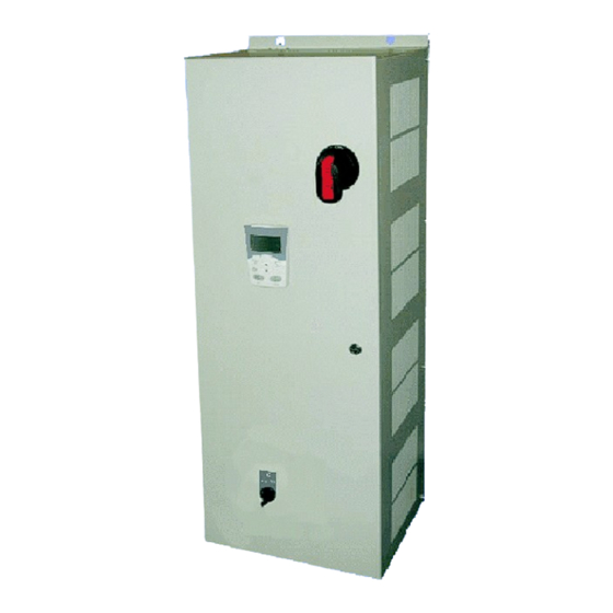
ACS550-CC Packaged Drive with Bypass Installation Study these installation instructions carefully before proceeding. Failure to observe the warnings and instructions may cause a malfunction or personal hazard. WARNING! Before you begin read "Safety" on page 1. WARNING! When the ACS550 with Bypass is connected to the line power, the Motor Terminals T1, T2, and T3 are live even if the motor is not running. - Page 7 ACS550-CC Packaged Drive with Bypass The following shows the front view of a typical ACS550 Bypass wall mount configuration, and identifies the major components. ACS-CP-A Control Panel Operating handle for Circuit Breaker Cover Control The following shows the front view of a typical ACS550 Bypass floor mount configuration, and identifies the major components.
-
Page 8: Installation Flow Chart
ACS550-CC Packaged Drive with Bypass The following is a typical power diagram. Drive with Bypass Drive Output Circuit Breaker Contactor ACS550 3 Phase Motor Drive Input Power Service Switch Bypass (Optional) Contactor Installation Flow Chart The installation of Bypass Configurations for ACS550 drives follows the outline below. -
Page 9: Preparing For Installation (Supplement To Acs550-01/U1 User's Manual)
ACS550-CC Packaged Drive with Bypass Preparing for Installation Lifting the Drive Floor Mounting Warning! Handle and ship floor mounted enclosures only in the upright position. These units are not designed to be laid on their backs. 1. Use a pallet truck to move the package/enclosure to the installation site. -
Page 10: Preparing For Installation (Supplement To Acs550-01/U1 User's Manual)
ACS550-CC Packaged Drive with Bypass Preparing for Installation Drive Identification To identify the type of device you are installing, refer to the type code number on the device identification label. • Wall mounting base drives – label attached on the side surface of the heat sink. -
Page 11: Installing The Drive (Supplement To Acs550-01/U1 User's Manual)
ACS550-CC Packaged Drive with Bypass nstalling the Drive Warning! Metal shavings or debris in the enclosure can damage electrical equipment and create a hazardous condition. Where parts, such as conduit plates require cutting or drilling, first remove the part. If that is not practical, cover nearby electrical components to protect them from all shavings or debris. -
Page 12: Installing The Wiring (Supplement To Acs550-01/U1 User's Manual)
ACS550-CC Packaged Drive with Bypass Installing the Wiring WARNING! • Metal shavings or debris in the enclosure can damage electrical equipment and create a hazardous condition. Where parts, such as conduit plates require cutting or drilling, first remove the part. If that is not practical, cover nearby electrical components to protect them from all shavings or debris. - Page 13 ACS550-CC Packaged Drive with Bypass Wiring Overview Connection Diagrams – ACS550-CC units are configured for wiring access from the top or the bottom. The following figures show the wiring connection points. Refer to the ACS550-01/U1 User's Manual for control connections to the drive.
- Page 14 ACS550-CC Packaged Drive with Bypass Install the Line Input Wiring Line Input Connections – Bypass Configurations Connect input power to the terminals of the circuit breaker. Connect the equipment grounding conductor to the ground lug at the top of the enclosure. The figures below show the connection points for typical configurations.
- Page 15 ACS550-CC Packaged Drive with Bypass Install the Motor Wiring Motor Connections – Bypass Configurations Connect the motor cables to the motor overload relay output terminals; see the figures below. The motor grounding conductor can be connected to the ground lug near the motor overload relay.
- Page 16 ACS550-CC Packaged Drive with Bypass Terminal Block 1TB Connection Points Basic control connections are made to 1TB, which is a din-rail terminal block on the back panel at the bottom of the enclosure. 1TB includes screw clamp terminals rated for #22-10 AWG stranded or solid wire. Recommended tightening torque is 4.4 - 7.1 in-lbs.
- Page 17 ACS550-CC Packaged Drive with Bypass Auto Start Contact To start the ACS550 by means of an external un-powered contact (maintained), connect the contact to 1TB:9 and 1TB:10. Closing this contact will start the motor when the drive is in the AUTO mode.
- Page 18 ACS550-CC Packaged Drive with Bypass Motor Overload Relay The ACS550 with Bypass includes a Class 20 motor overload relay to provide thermal motor protection. Suggested Settings Current Set the current adjustment to the value of the full load current shown on the motor nameplate.
-
Page 19: Maintenance
Maintenance Interval If installed in an appropriate environment, the drive requires very little maintenance. The table lists the routine maintenance intervals recommended by ABB. The information shown below is supplemental and in addition to that shown in the ACS550-01/U1 User’s Manual. -
Page 20: Technical Data
ACS550-CC Packaged Drive with Bypass Technical Data Ratings Note! The ratings listed below are additions to the ratings listed in the ACS550-01/ U1 User’s Manual. Ratings, 380…480 Volt Drives Valid up to 40°C (104 °F) Type Code Normal Use Heavy-Duty Use... - Page 21 ACS550-CC Packaged Drive with Bypass 208…240 Volt Fuses 208… 240 Volt Drive Input Fuse Ratings Frame Amps Bussmann Size Identification (600V) Type ACS550-CC-04A6-2 KTK-R-15 ACS550-CC-06A6-2 KTK-R-15 ACS550-CC-07A5-2 KTK-R-15 ACS550-CC-012A-2 KTK-R-15 ACS550-CC-017A-2 KTK-R-30 ACS550-CC-024A-2 KTK-R-30 ACS550-CC-031A-2 JJS-50 ACS550-CC-046A-2 JJS-80 ACS550-CC-059A-2 JJS-80...
- Page 22 ACS550-CC Packaged Drive with Bypass 380…480 Volt Fuses 380… 480 Volt Drive Input Fuse Ratings Frame Amps Bussmann Size Identification (600V) Type 1/1.5 ACS550-CC-03A3-4 KTK-R-15 ACS550-CC-04A1-4 KTK-R-15 ACS550-CC-06A9-4 KTK-R-15 ACS550-CC-08A8-4 KTK-R-15 ACS550-CC-012A-4 KTK-R-15 ACS550-CC-015A-4 KTK-R-30 ACS550-CC-023A-4 KTK-R-30 ACS550-CC-031A-4 JJS-50 ACS550-CC-038A-4...
- Page 23 ACS550-CC Packaged Drive with Bypass Fuses, 500…600 Volt, Fuses 500…600 Volt Drive Input Fuse Ratings Frame Amps Bussmann Size Identification (600V) Type ACS550-CC-02A7-6 KTK-R-15 ACS550-CC-03A9-6 KTK-R-15 ACS550-CC-06A1-6 KTK-R-15 ACS550-CC-09A0-6 KTK-R-15 ACS550-CC-011A-6 KTK-R-30 ACS550-CC-017A-6 KTK-R-30 ACS550-CC-022A-6 JJS-50 ACS550-CC-027A-6 JJS-50 ACS550-CC-032A-6 JJS-100...
- Page 24 ACS550-CC Packaged Drive with Bypass Power Connection Terminals The following tables show maximum wire size and required tightening torque for incoming power and motor terminals, and grounding terminal lug information. 208…240 Volt, Terminals 208…240 Volt, Power Connection Terminal Data 208…240 Volt...
- Page 25 ACS550-CC Packaged Drive with Bypass 380…480 Volt, Terminals 380…480 Volt, Power Connection Terminal Data 380…480 Volt Base Power Wiring Size Drive Circuit Overload Frame Type Code Ground Lugs Breaker Relay Size 1/1.5 ACS550-CC-03A3-4 ACS550-CC-04A1-4 ACS550-CC-06A9-4 35 in-lbs ACS550-CC-08A8-4 13 in-lbs...
- Page 26 ACS550-CC Packaged Drive with Bypass 500…600 Volt, Terminals 500…600 Volt, Power Connection Terminal Data 500…600 Volt Base Power Wiring Size Drive Circuit Overload Ground Frame Type Code Breaker Relay Lugs Size ACS550-CC-02A7-6 ACS550-CC-03A9-6 ACS550-CC-06A1-6 62 in-lbs ACS550-CC-09A0-6 13 in-lbs ACS550-CC-011A-6...
-
Page 27: Motor Connections (Supplement To Acs550-01/U1 User's Manual)
ACS550-CC Packaged Drive with Bypass Motor Connections Motor Terminals See preceding “Power Connection Terminal Data” tables. Bypass Contactors The bypass circuit in the ACS550 Bypass includes two contactors. One contactor is the bypass contactor (2M) that can be used to connect the motor directly to the incoming power line in the event that the ACS550 is out of service. -
Page 28: Motor Connection Specifications - R7/R8
ACS550-CC Packaged Drive with Bypass Motor Connection Specifications – R7/R8 Motor Connection Specifications Max. Motor Cable Length* Frame Size Maximum Motor Cable = 1 or 4 kHz = 8 kHz or 12 kHz Length R7…R8 300 m 980 ft Does not apply * Warning! Using a motor cable longer than specified in the chart above may cause permanent damage to the drive. -
Page 29: Dimensions And Weights (Supplement To Acs550-01/U1 User's Manual)
ACS550-CC Packaged Drive with Bypass Dimensions and Weights Dimensional References The following tables contain dimensional references that will be needed to identify the dimensional information applying to a given device type code. 208/230V Bypass Packages UL Type UL Type UL Type... - Page 30 ACS550-CC Packaged Drive with Bypass 480V Bypass Packages UL Type UL Type UL Type (NEMA) 1 (NEMA) 12 (NEMA) 3R Dim. Ref. Page 29 Dim. Ref. Page 30 Dim. Ref. Page 31 Type Coxe Amp Frame ACS550-CC-03A3-4 CX1-1 CX12-1 CX3R-1...
- Page 31 ACS550-CC Packaged Drive with Bypass Dimensions: ACS550-CC NEMA 1 R1 through R8 Frame Size Wall Mount (CX1-1 - CX1-8) Wall Mount (CX1-9 - CX1-11) Floor Mount (CX1-12 - CX1-13) UL Type / NEMA 1 UL Type / NEMA 1 Mounting Dimensions...
- Page 32 ACS550-CC Packaged Drive with Bypass Dimensions: ACS550-CC NEMA 12 R1 through R8 Frame Size Wall Mount (CX12-1 - CX12-9) Wall Mount (CX12-10) Floor Mount (CX12-11 - CX12-13) UL Type / NEMA 12 UL Type / NEMA 12 Mounting Dimensions Dimensions and Weights...
- Page 33 ACS550-CC Packaged Drive with Bypass Dimensions: ACS550-CC NEMA 3R R1 through R6 Frame Size Wall Mount (CX3R-1 - CX3R-7) Floor Mount (CX13R-8) UL Type / NEMA 3R UL Type / NEMA 3R Mounting Dimensions Dimensions and Weights Dimension mm [inches]...
-
Page 34: Applicable Standards
ACS550-CC Packaged Drive with Bypass Applicable Standards Drive compliance with the following standards is identified by the standards “marks” on the type code label. Mark Applicable Standards UL 508C and UL Standard for Safety, Power Conversion Equipment, and C22.2 No. 14... - Page 35 ACS550-CC Packaged Drive with Bypass Index Numerics 208/230V bypass packages ....27 Floor mount installing the line input wiring ... . . 12 480V bypass packages .
- Page 36 ACS550-CC Packaged Drive with Bypass NEMA 1 Technical data ......18–32 code ....... . 8 Terminal block 1TB.
- Page 37 ABB Inc. Automation Products Low Voltage Drives 16250 West Glendale Drive New Berlin, WI 53151 Telephone 2 62 785-3200 Fax 2 62 780-5135 Internet www.abb.us/drives www.abb-drives.com...
Need help?
Do you have a question about the ACS550-CC and is the answer not in the manual?
Questions and answers