Table of Contents
Advertisement
Quick Links
PLEASE read these instructions carefully before attempting to rebuild your carburetor. Make sure to refer to your carburetor Owner's Manual for further
information, if need be. If you have any questions or problems, do not hesitate to contact our Technical Hotline at :1-800-416-8628.
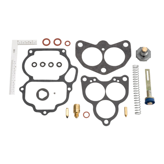
To check kit contents, see the exploded views of the carburetor and parts descriptions on the last page. Verify that all parts underlined on the list are
in your kit. Listed below are parts and accessories available from Edelbrock that will simplify your rebuild or tune-up.
DISASSEMBLY:
1.
Disconnect all throttle linkages and remove the carburetor from the car. Loosen and remove the five bolts retaining the carburetor air horn (top)
to the fuel bowl (middle) and pull them apart. Pour any fuel in the bowl into a suitable receptacle. Pull out the float hinge pin to remove the float
and fuel inlet needle then use a screwdriver to remove the fuel inlet seat.
2.
Remove the two screws retaining each venturi cluster hold down then remove the clusters. Remove the brass air bleed and emulsion tube from
each venturi cluster. Remove the accelerator pump discharge nozzle and needle. Remove the pin that attaches the accelerator pump arm to the
pump cam at the end of the throttle shaft, then pull the accelerator pump out of its provision. Remove the brass fuel bowl plugs from the front of
the carburetor. Remove the fuel jets by inserting a screwdriver into the holes on the front of the fuel bowl previously blocked by the plugs. Loosen
and remove the 3 bolts retaining the carburetor base (bottom) to the fuel bowl (middle) and pull them apart.
3.
Remove the power valve from the bottom of the fuel bowl. Back the idle mixture screws completely out of the carburetor base. Inspect each
section for signs of abnormal wear and/or damage.
CLEANING:
Clean all parts thoroughly in an approved cleaning solvent such as carb cleaner. Special attention should be given to carbon deposits in throttle
bores and passages. Do not use wires or pointed tools to clean passages and calibrated holes as calibration of carburetor may be destroyed. Use
of a soft copper or aluminum wire to clean any debris out of orifices is recommended. Do not immerse rubber or similar materials in cleaning
solvent. Use compressed air to blow out each passage.
REASSEMBLY (The following is a general overview only, NOT a step-by-step procedure):
Reverse Disassembly sequence using the exploded view as a guide and note the following special instructions.
1.
To ensure proper usage of gaskets and parts packaged in kit use old gaskets and parts for identification.
2.
Idle mixture screws should be seated lightly and then backed out approximately 1-1/2 to 2 turns to return them to the baseline setting.
3.
Apply a light film of lubricant to the cup of the accelerator pump plunger assembly before installing.
4.
Reinstall the venturi assemblies in their proper location with the new gaskets supplied. If the venturi clusters get mixed up, locate the small
tab at the base of one arm of each cluster. This tab will point inward toward the other venturi cluster.
6.
Adjust the float level and drop using the procedure outlined below and in the Carburetor Owner's Manual. Be sure the fuel float does not hang
up during reassembly or the float setting could be upset, resulting in poor performance, flooding and the possibility of an engine fire.
7.
If the idle speed screw setting has been disrupted, the factory setting is two full turns back from seated. Refer to the Carburetor Owner's
Manual for adjustment specifications and procedures.
8.
Install the accelerator pump linkage. The linkage is installed in the third hole from the cam retaining screw, giving the largest pump shot,
from the factory. Use the first or second hole if a smaller pump shot is desired.
•
FLOAT LEVEL (FIG. 1)
With the air horn assembly inverted and the weight of the float resting on a fully seated needle, there should be
roughly 1-13/32" between the bottom of the float and the bowl cover gasket surface (not the gasket itself). To
adjust, bend the float lever. CAUTION! DO NOT PRESS NEEDLE INTO SEAT WHEN ADJUSTING FLOAT LEVER.
•
FLOAT DROP (FIG. 2)
With the air horn held in an upright position, adjust the stop tab on the float bracket to achieve approximately
1-3/4" between the bottom of the float and the bowl cover gasket surface. To adjust, bend the tab on float lever.
FIG. 1
Part #1154
Rev. 12/10 - AJ/mc
®
Edelbrock 94 Carburetor Rebuild Kit
FIG. 2
Part #1154
INSTALLATION INSTRUCTIONS
Metering Jets (Sold in Pairs):
Orifice Size
.049"
.050"
.051"
.052"
.053"
.054"
.055"
.056"
.057"
Power Valves:
Rating
4.5" Hg
5.5" Hg
6.5" Hg
©2010 Edelbrock LLC
Brochure # 63-1154
Part #
#1160
#1161
#1162
#1163
#1164
#1165
#1166
#1167
#1168
Part #
#1170
#1171
#1172
Advertisement
Table of Contents

Related Manuals for Edelbrock 94


Summary of Contents for Edelbrock 94
-
Page 1: Installation Instructions
To check kit contents, see the exploded views of the carburetor and parts descriptions on the last page. Verify that all parts underlined on the list are in your kit. Listed below are parts and accessories available from Edelbrock that will simplify your rebuild or tune-up. - Page 2 EXPLODED VIEW OF EDELBROCK 94 CARBURETOR Accelerator Pump Venturi Cluster Bowl Assembly Air Horn Assembly Base Assembly Part #1154 ©2010 Edelbrock LLC Rev. 12/10 - AJ/mc Brochure # 63-1154...
Need help?
Do you have a question about the 94 and is the answer not in the manual?
Questions and answers