
Related Manuals for Clarke CA90 32T


Summary of Contents for Clarke CA90 32T
-
Page 1: Service Manual
Clarke CA90 32T™ Service Manual Model Numbers: Clarke 810T English 11/2015 - Form No. 56043170... -
Page 2: Table Of Contents
Service Manual – CA90 32T Table of Contents Contents Service Manual . . . . . . . . . . . . . . . . . . . . . . . . . . . . . . . . . . . . . . . . 1 General Information Machine Description . - Page 3 Service Manual – CA90 32T Table of Contents Shop Measurements . . . . . . . . . . . . . . . . . . . . . . . . . . . . . . . . . . . 31 Scrub System Functional Description .
-
Page 4: General Information
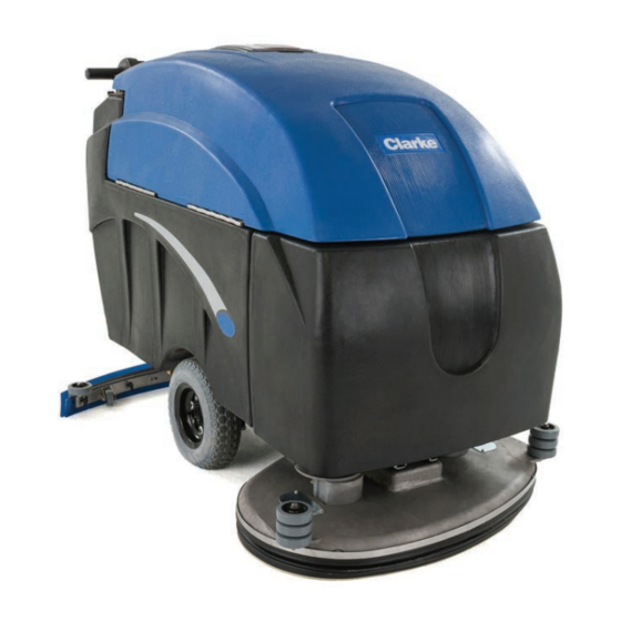
General Information Machine Description The CLARKE CA90 32T is a battery powered walk-behind automatic floor scrubber. It is intended for use in large commercial facilities such as hospitals, schools, factories, and retail stores. The CLARKE CA90 32T is equipped with (2) counter rotating pad/brush holders to provide a 32 inch cleaning path. -
Page 5: Conventions
Machine Transportation General Machine Description The Clarke CA90 32T is a battery powered, walk-behind scrubber. It is a heavy duty machine built and designed to clean large open areas of hard surface flooring. It is equipped with a gravity feed solution system for dispensing cleaning solution onto the floor, (2) rotating brush motors for scrubbing, and a recovery system for removing the dirty solution from the floor. -
Page 6: General Safety Instructions
Service Manual – CA90 32T General Information General Safety Instructions Specific Cautions and Warnings are included to warn you of potential danger of machine damage or bodily harm. This machine is for commercial use, for example in hotels, schools, hospitals, factories, shops and offices other than normal residential housekeeping purposes. -
Page 7: Nameplate
Service Manual – CA90 32T General Information Nameplate The nameplate contains important identification information which will be needed when ordering parts: Model number, Description, and Serial number. Machine Specifications Specification Standard Metric Cleaning Path 32 Inches 80 cm Solution Tank... -
Page 8: Component Locations
Service Manual – CA90 32T General Information Component Locations Battery Brush Brush Vacuum Hour Solution Brush UP/ Status Pressure Switch Switch Meter Switch DOWN Switch Indicator Meter Drain Hose Circuit Breakers Squeegee Assembly Squeegee Lift Handle Solution Solution Rear Fill... - Page 9 Service Manual – CA90 32T General Information Operating Triggers Reverse Switch Key switch Solution fill (Pail) Console Adjustment Levers Speed Control Knob Solution Flow control knob...
-
Page 10: Preventative Maintenance
Service Manual – CA90 32T General Information Preventative Maintenance DAILY WEEKLY MONTHLYMonthly Recharge Batteries Remove and clean Pad driver/ Brush Drain and rinse recovery tank. Check for solid debris Remove squeegee assembly, and wipe it down with a damp cloth... -
Page 11: Chassis System
Chassis System Functional Description The Clarke CA90 32T uses a welded steel chassis to support the machine. Bolted to the chassis are the solution tank, transaxle, casters, squeegee bracket, and brush deck supports. Also, the main wiring harness travels through one of the channels of the chassis. -
Page 12: Control System
Functional Description The CLARKE CA90 32T has (1) controller for the traction drive, and switches and solenoids for the other systems. The traction drive controller is a Curtis model 1228-3430. The inputs for the Curtis Speed Control are B+, B - , Keyswitch enable, Forward/Reverse switch, and the Speed Control Potentiometer. - Page 13 Service Manual – Machine Name Control System Brush Switch Vacuum Solution Actuator Up/ Motor Switch Switch Down Switch Trigger Switch (looking up through lower housing panel) Forward/Reverse Switch...
- Page 14 Service Manual – CA90 32T Control System Solution control knob Speed control knob Brush Solenoid MAIN Solenoid Vacuum Solenoid Circuit Breakers (Located on lower control housing panel...
-
Page 15: Maintenance And Adjustment
Service Manual – CA90 32T Control System Maintenance and Adjustment No maintenance or adjustment is required for the control system... -
Page 16: Electrical System
Service Manual – CA90 32T Electrical System Electrical System Functional Description The electrical system consists of switches, circuit breakers, and contactors mounted inside the control housing, and inside the battery compartment. The battery charger is a “shelf” style charger which is 36 volts DC, and has an output of 25 amps maximum. - Page 17 Service Manual – Machine Name Electrical System The machine wiring is color coded, and the wires are marked with yellow numbered bands corresponding to their location on the Wiring Harness Diagram.
-
Page 18: Wiring Harness Diagram
Service Manual – CA90 32T Electrical System Wiring Harness Diagram Electrical Circuit Diagram (Owner’s Manual) BATTERY CAPACITY LIGHTS HOUR METER BRUSH VACUUM SOLUTION DOWN (16AWG GRN) SWITCH SWITCH SWITCH ACTUATOR TRIGGER SWITCH (16AWG WHT) DIRECTION (16AWG WHT) SWITCH DRIVING MOTOR... -
Page 19: Electrical Circuit Diagram (Ladder Style)
Service Manual – CA90 32T Electrical System Electrical Circuit Diagram (ladder style) 36V Battery Battery Capacity Lights Main Solenoid Direction Switch Drive Motor Driving Motor Speed Controller Solution Switch Switch Solution Solenoid Trigger Switch Brush Switch Hour Meter Left Brush Motor... -
Page 20: Battery Connections
Service Manual – CA90 32T Electrical System Battery Connections • The batteries should be connected in series as shown in the diagram below. • Battery terminals and cables should be cleaned and checked periodically. • Apply a coating or protective spray on the cable connections to prevent corrosion. -
Page 21: Basic Troubleshooting
Service Manual – CA90 32T Electrical System Basic Troubleshooting Problem Cause Correction • No Power • Key not in “ON” position • Turn Key to “ON” position • Main circuit breaker tripped • Reset Main breaker • Batteries need charge •... -
Page 22: Recovery System
Recovery System Functional Description The recovery system on the CA90 32T is made up of a 3-stage vacuum motor, various pipes and hoses, and a ball-float assembly. The “working air” from the vacuum motor passes through the recovery tank standpipe, the ball-float assembly, then down to the squeegee. -
Page 23: Component Locations
Service Manual – CA90 32T Recovery System Component Locations • Vacuum Motor • Vacuum Switch • Vacuum Solenoid • Vacuum Circuit Breaker • Ball-Float Assembly • Pick-up Tube Adapter • Vacuum (pick-up) Hose • Drain Hose Vacuum Motor Vacuum Switch... - Page 24 Service Manual – Machine Name Recovery System Vacuum Solenoid Vacuum Circuit Breaker Ball Float Assembly...
- Page 25 Service Manual – CA90 32T Recovery System Pick-up Tube Adapter Vacuum (pick- up) Hose Drain Hose Connection at Recovery Tank Other end of Drain Hose with Stopper...
-
Page 26: Maintenance And Adjustment
Service Manual – CA90 32T Recovery System Maintenance and Adjustment Check ball-float operation • Open the recovery tank cover • Remove the ball-float from the stand-pipe adapter (it just slips onto the adapter fitting) • The ball should move freely inside it’s cage all the way to the top, and all the way to the bottom. -
Page 27: Checking Vacuum Motor Carbon Brushes
Service Manual – CA90 32T Recovery System Checking Vacuum motor carbon brushes • Remove the vacuum motor from the machine (see the removal instructions below) • Remove the (2) screws that attach the plastic cover Cover Screws (x 2) • Remove the (2) screws that attach each carbon brush... - Page 28 Service Manual – CA90 32T Recovery System...
-
Page 29: Troubleshooting
Service Manual – CA90 32T Recovery System Troubleshooting PrProblem Cause Correc tion • No Vacuum Motor Operation • Vacuum circuit breaker tripped • Reset circuit breaker • Defective vacuum motor • Replace vacuum motor (Other functions work) • Defective vacuum solenoid •... -
Page 30: Removal And Installation
Service Manual – CA90 32T Recovery System Removal and Installation Vacuum motor Removal: • Completely drain the recovery tank • Turn the keyswitch to OFF. • Lift the left side of the recovery tank, and insure the recovery tank support bracket latches into place. -
Page 31: Specifications
Service Manual – CA90 32T Recovery System • • Re-install the (3) nuts/washers to slightly compress the gasket. (NOTE: Do not over-tighten ! Damage to the vacuum motor can occur) • Re-connect the vacuum motor connector. (NOTE: If you have replacement heat shrink, use it to cover the... -
Page 32: Scrub System
Functional Description The scrub system on the CA90 32T is composed of (2) disc style brush motors. These motors rotate toward the center of the machine to sweep solution and dirt toward the center of the squeegee path. The RIGHT motor spins conter-clockwise, and the LEFT motor spins clockwise. -
Page 33: Circuit Diagram
Service Manual – CA90 32T Scrub System Circuit Diagram Trigger Switch Brush Switch Key Switch Hour meter Left Brush Brush Pressure Circuit Motor Meter Breakers Brush Solenoid Right Brush Motor Figure 1: Brush Circuit Actuator Switch Switch Actuator Motor Figure 2: Actuator Circuit... -
Page 34: Component Locations
Service Manual – CA90 32T Scrub System Component Locations • Linear Actuator • Brush motors • Brush Deck • Drive Plate Access Panel • Drive Plate Assembly • Brush Pressure Gauge • Brush Circuit Breakers • Brush Solenoid Linear Actuator... - Page 35 Service Manual – CA90 32T Scrub System Drive Plate Assembly Brush Pressure Gauge Actuator Switch Left Brush Right Brush Circuit Breaker Circuit Breaker...
-
Page 36: Maintenance And Adjustment
Service Manual – CA90 32T Scrub System Brush Solenoid Maintenance and Adjustment Adjusting the Scrub Deck height for best performance • While the machine is in full operation (Brushes turning, solution flowing, and moving forward) use the Linear Actuator switch to adjust the Brush Pressure Gauge just into the white line between RED and GREEN. -
Page 37: Replacement Of Carbon Brushes
Service Manual – CA90 32T Scrub System Replacement of Carbon Brushes • Turn the machine key switch to OFF. • Dis-connect the batteries from the machine. • Remove the front shroud to access the brush motors. • Remove the wire ties, and dis-connect the brush motor connectors. - Page 38 Service Manual – CA90 32T Scrub System • With the case removed, you can access the carbon brushes. NOTE: Pay attention to the way the carbon brush wires are folded up. The photos in this section had the wires moved to show the detail of the brush and spring.
-
Page 39: Troubleshooting
Service Manual – CA90 32T Scrub System • Re-assemble the motor to the gearbox. There are timing marks on the case, and the aluminum ends. Make sure these are aligned. • Re-install the (2) motor screws. NOTE: The magnets inside the case will try to pull these inward. -
Page 40: Removal And Installation
Service Manual – CA90 32T Scrub System Removal and Installation Brush Motor Removal • Completely drain the recovery tank. • Lift the recovery tank, and secure the tank support latch. • Remove the front cover of the machine by removing the (4) knobs. -
Page 41: Installation
Service Manual – CA90 32T Scrub System • Dis-connect the motor connector. (NOTE - There may be protective heat shrink over the connector. If so, carefully cut away the heat shrink)) • Lift the motor out. Installation • Set the new motor in approximately the same location as the motor removed. (NOTE: This should be fairly easy to see due to the dirt build-up around the mounting bolts) •... -
Page 42: Installation
Service Manual – CA90 32T Scrub System • Remove the cotter pin, and remove the upper mounting pin. • Cut the wire ties that secure the connector bundle. • Disconnect the (2) actuator wires. • Remove the hairpin from the lower mounting pin, and remove the lower mounting pin. -
Page 43: Component Specifications (Electrical)
Service Manual – CA90 32T Scrub System • Place the tube portion of the actuator into the spring bracket so the holes line up. • Insert the lower mounting pin, and secure it with the hairpin. • Position the upper end of the actuator into the actuator bracket. -
Page 44: Solution System
Service Manual – CA90 32T Solution System Solution System Functional Description The solution system is gravity feed. Meaning there is no pump for the solution. The solution system is fed by (2) tubes which are connected to hose barbs at the bottom rear of the solution tank. The solution then passes through a solution shut-off valve, and the solution filter. -
Page 45: Component Locations
Service Manual – CA90 32T Solution System Component Locations • Solution Tank • Solution Shut-off Valve • Solution Filter • Solution Valve (solenoid) • Solution Flow Adjustment Knob • Solution Switch Solution Tank Solution Shut-off Valve Solution Filter... - Page 46 Service Manual – Machine Name Solution System Solution Valve Solution Switch Solution Flow Adjustment Knob...
-
Page 47: Maintenance And Adjustment
Service Manual – CA90 32T Solution System Maintenance and Adjustment Solution Filter Cleaning Work near a floor drain for convenient clean up if possible. Turn the key switch OFF. Close the Solution shut-off valve (The valve is closed when the handle is NOT in line with the hose) Unscrew the solution filter cover Remove and clean the screen. -
Page 48: Troubleshooting
Service Manual – CA90 32T Solution System Troubleshooting Problem Cause Correction • Solution switch not in “ON” • Turn Solution switch to the position “ON” position No Solution Flow • Solution switch is defective • Replace Solution switch • Solution Solenoid is defective •... -
Page 49: Specifications
Service Manual – CA90 32T Solution System Now you can pull the valve out a bit to access the allen screw that attaches the adjust cable to the adjustment shaft of the valve. 10. Loosen the allen screw, and disconnect the cable from the valve. -
Page 50: Squeegee System
Squeegee System Functional Description The CLARKE CA90 32T uses a parabolic style squeegee assembly attached to a swiveling squeegee mount bracket with (2) thumb screws. The squeegee is raised and lowered manually using the squeegee lift lever, and the squeegee lift cable. Down pressure on the squeegee is obtained by using a spring between the squeegee mount bracket and the machine chassis. - Page 51 Service Manual – Machine Name Squeegee System Squeegee Lift Handle Squeegee Lift Cable Squeegee Bracket Assembly Squeegee Bracket Tension Spring Squeegee Angle Adjust Knob...
-
Page 52: Maintenance And Adjustment
Service Manual – CA90 32T Squeegee System Maintenance and Adjustment Adjusting the Squeegee Assembly Angle • The rear squeegee blade should be adjusted so that there is a gentle deflection to the rear across the entire blade while traveling in the forward direction. This deflection places the edge of the squeegee blade in the proper position for “wiping”... -
Page 53: Troubleshooting
Service Manual – CA90 32T Squeegee System Troubleshooting Problem Cause Correction Vacuum leak(s) due to: • Leaky Vacuum hose • Check the vacuum hose, and tighten/replace as necessary • Damaged pick-up adapter gasket • Replace adapter gasket • Drain plug not installed •... -
Page 54: Wheel System, Traction
Wheel System, Traction Functional Description The Clarke CA90 32T traction drive is controlled by a Curtis Model 1228-3430 controller. Inputs into the controller are the key switch, the trigger switch, the forward/reverse switch, and the speed control potentiometer. Battery + and Battery - are wired through the MAIN solenoid to the controller at terminals B1 and B2. - Page 55 Service Manual – CA90 32T Wheel System, Traction Transaxle Transaxle Motor MAIN Solenoid...
- Page 56 Service Manual – CA90 32T Wheel System, Traction Trigger Switch (looking up through lower housing panel) Forward/Reverse Switch...
- Page 57 Service Manual – CA90 32T Wheel System, Traction Speed Control Potentiometer (With knob attached) Speed Control Potentiometer Assembly Curtis Speed Controller Mounted in control housing...
-
Page 58: Maintenance And Adjustment
Service Manual – CA90 32T Wheel System, Traction Maintenance and Adjustment The (2) rear casters should be greased every (6) months. There is no other maintenance or adjustments required in the traction system. Troubleshooting Problem Cause Correction No drive • Defective Trigger Switch •... -
Page 59: Speed Control Potentiometer
Service Manual – CA90 32T Wheel System, Traction 11. Install the new transaxle by following these steps in the reverse order. NOTE 1: The transaxle must be oriented as shown in the picture above to clear the solution filter. NOTE 2: The transaxle slots in the frame will align with the square ends of the transaxle housing, so there is no need to worry about side-to-side alignment. -
Page 60: Trigger Switch
Service Manual – CA90 32T Wheel System, Traction Trigger Switch Disconnect the batteries. Remove the (4) screws from the upper control housing panel (dash board), and the (4) screws from the lower control housing panel. GENTLY move them aside to gain access to the inside of the control housing. (See picture above) Use a needle nose pliers (needle nose vice grips work the best) to hold the nylock nut on top of the switch. -
Page 61: Curtis Speed Controller
Service Manual – CA90 32T Wheel System, Traction Curtis Speed Controller NOTE: Replacing the Curtis Speed Controller is quite difficult. This unit has proven VERY reliable, and 99% of the time there are drive issues, the problem is something OTHER than the speed controller. -
Page 62: Shop Measurements
Service Manual – CA90 32T Wheel System, Traction Shop Measurements Measurement at Pin Circumstances Voltmeter Reading Curtis Controller Pin 18 Trigger On 4.5 volts DC Trigger Off .7 volts DC Curtis Controller Pin 17 Reverse On & Trigger On 37.1 volts DC...
Need help?
Do you have a question about the CA90 32T and is the answer not in the manual?
Questions and answers