Table of Contents
Advertisement
Advertisement
Table of Contents

Related Manuals for Keith WALKING FLOOR Workhorse


Summary of Contents for Keith WALKING FLOOR Workhorse
- Page 1 OWNER’S MANUAL Version: English, 002, June 2008 Updated 7/12/17...
-
Page 2: Table Of Contents
® system ..............2.1 Use of the WALKING FLOOR system ................2.2 Operation of the WALKING FLOOR system ..............Technical specifications of the WALKING FLOOR Workhorse ..........3.1 Specifications of the hydraulic installation ................ Operation ..........................4.1 Manual operation ...................... -
Page 3: Introduction
KEITH WALKING FLOOR Europe is not responsible for any misinterpretation or errors. © 2008, KEITH Mfg. Co. All rights reserved. KEITH. KEITH logo, WALKING FLOOR are registered trademarks of KEITH Mfg. Co. Equipment manufactured by KEITH Mfg. Co. is protected by numerous patents both domestic and foreign. WALKING FLOOR® is a product and brand of KEITH Mfg. Co. -
Page 4: Description Of The Walking Floor
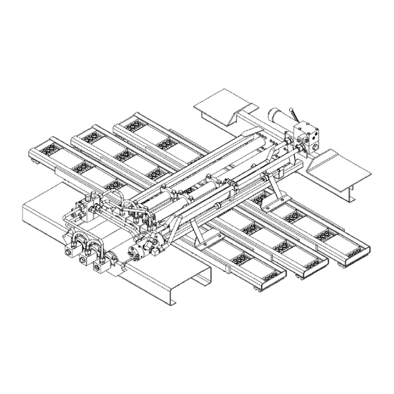
4 LOAD / UNLOAD BLOCK 6 CYLINDER (3) Figure 1.1: KEITH WALKING FLOOR Workhorse drive-unit Three double-acting hydraulic cylinders move the floor slats in a cycle with four phases. The forces exerted by the cylinders are transferred to the slats by three cross drives. Each cross drive moves 1/3 of the total number of floor slats. - Page 5 ® ® KEITH Walking Floor Workhorse Oil flow diagram Figure 1.2a Phase 1: Cylinder 1 (and slats #1) moves towards the front of the bunker. Because only 1/3 of the floor is moving, whereas 2/3 of the floor is not, the load will not move (the friction of this major floor area exceeds the friction force caused by the Walking Floor slats).
- Page 6 ® ® KEITH Walking Floor Workhorse Oil flow diagram Figure 1.2b Cylinder 3 (and slats #3) moves towards the front of the bunker; again the load re- Phase 3: mains still. At the end of the stroke, when all cylinders are lined up, an actuator at- tached to the cross drive mechanically switches the switching valve.
- Page 7 The position of the two control valves (internal) determines the loading or the unloading cycle. A manual or electrical load- / off- / unload valve operates these valves. The (un)loading time is determined by the speed of action of the cylinders, which depends on oil flow to the cylinders and the cylinder size.
-
Page 8: Technical Specifications Of The Walking Floor Workhorse
3. Specifications of the WALKING FLOOR Workhorse drive unit Cylinders standard ø 102 mm stroke 200 mm. Weight 477 kg. Capacity ø 102 mm 26.300 kg. at 140 bar Pump max. 210 bar max. 110 l/min. 3.1 Specifications of the hydraulic installation Always consult the supplier of your drive unit to ensure you choose the correct hydraulic power unit. - Page 9 The KEITH ® WALKING FLOOR ® Workhorse System is designed for a recommended maximum oil flow of 110 l/minute. And a recommended maximum speed of 2.6 m/min. A high power take-off (PTO) ratio (greater than 1:1) reduces the size of the pump for a given rotational speed.
-
Page 10: Operation
4. Operation WARNING: The large force exerted by the floor can result in damage to equipment and serious injury or death. Always ensure that this manual has been read and understood by the operator. Take the following precautionary measures: • First open the doors before switching on the pump. •... -
Page 11: Manual Operation
4.1 Manual operation Starting the floor operation: 1. Open the trailer doors. 2. Attach the hydraulic quick couplings to one another. 3. Turn on the PTO and bring the engine to the desired number of revolutions (rpm). Unloading / loading: 1. -
Page 12: Electric Operation
4.2 Electric operation Starting the floor operation: 1. Open the trailer doors. 2. Attach the hydraulic quick couplings to one another. 3. Turn on the PTO and bring the engine to the desired number of revolutions (rpm). Unloading / loading: 1. - Page 13 Emergency stop The system with an optional KEITH ® electrical control box is provided with an emergency stop push button. If a dangerous situation arises during the operation of the floor it can be stopped immediately with the emergency stop.
-
Page 14: Electrical Control Load / Unload / On / Off
4.2.1 Electrical control Load / Unload / On / Off... -
Page 15: Electrical Control On / Off
4.2.2 Electrical control On / Off... -
Page 16: Components
The large force and pressure caused by the hydraulic forces in the system can cause serious injuries. Always switch off the pump during maintenance or service work. 5.1 The cylinder The three cylinders are the drive elements in the KEITH WALKING FLOOR system. ®... -
Page 17: The Check Valve
5.2 The check valve The four check valves are the sensors of the KEITH system. The check valve WALKING FLOOR ® ® detects when the cylinder has reached the end of its stroke and opens in order to allow the oil from the following cylinder to flow to the reservoir. -
Page 18: The Control Valve
5.5 The control valve This valve, which is manually operated, determines the direction of movement of the system. The valve has two positions: -Fully Withdrawn ; unloading -Fully Depressed; loading. Before the floor system is started the correct direction must be set. 1 Valve housing 2 Valve coil 3 Handle... -
Page 19: Installation Of Floor Slat With Kwik-Klamp ® System
5.7 Installation of the floor slat with Kwik-Klamp System ®... -
Page 20: Walking Floor Workhorse System Maintenance
® WARNING: The large force and pressure can cause serious injuries. Always switch off the pump during maintenance or service work. Two conditions that contribute to the life of the KEITH WALKING FLOOR system are: ® • Clean oil, free from contamination •... -
Page 21: Solving Problems
WARNING: The large force and pressure can cause serious injuries. Always switch off the pump during maintenance or service work. If you experience problems with the operation of your KEITH system this section can help you to find a solution and to make WALKING FLOOR ®... - Page 22 1.Switching valve 2.Flat Washer M10 3.Nut M10 4. Plastic stop ring 5. threaded rod M10 6. Bracket Figure 7.1 : Adjustment of the switching valve PROBLEM B: Cycle runs incorrectly for unloading: 1. Cylinders 1 and 2 move together to the front. Cause: The check valve on the front of cylinder 1 is not functioning correctly.
-
Page 23: Emergency Provision
7.1 Emergency Provision The Electric On / Off valve: The on/ off valve, controlled electrically, starts and stops the operation of the floor. In the <OFF> position, the oil flows via the valve directly back to the oil reservoir. NOTE: the system will not work if the pressure- and return hydraulic piping are not correctly connected. -
Page 24: Warranty
KEITH Mfg. Co.’s sole liability under this warranty and the owner’s sole and exclusive remedy is, Limited to repair or replacement of the defective part(s) at a facility authorized by KEITH Mfg. Co. This is the owner’s sole and exclusive remedy for all contract claims, and All tort claims including those based on the strict liability in tort and negligence. -
Page 25: Warranty Conditions
Tort Disclamer: •KEITH Mfg. Co. shall not have any liability in tort with respect to the products, including any liability based on strict liability in tort and negligence. If This Warranty Violates Law: •To the extent any provision of this warranty, contravenes the law of any jurisdiction, that provision shall be inapplicable in such jurisdiction and the remainder of the warranty shall not be affected there- 8.1 Warranty conditions... -
Page 26: Registration Card
_ _ _ _ _ _ _ _ _ _ _ _ _ _ _ _ _ _ _ _ _ N.B. IN ORDER TO SUBMIT A CLAIM UNDER THE GUARANTEE, THIS REGISTRATION CARD MUST BE SENT TO KEITH WALKING FLOOR EUROPE WITHIN 10 DAYS OF PURCHASE. - Page 27 Cross-Drive Assembly with Kwik Klamp System WORKHORSE DRIVE Notes: 1. This view is an inverted bottom view of the Cross-Drive Assemblies. 2. Both #2 assemblies are identical, however one unit is rotated 180° as shown above.
- Page 28 Electric On/Off w/ Integrated Filter Conversion Kit WORKHORSE DRIVE ID# QUANTITY DESCRIPTION PART# Workhorse Drive Conversion Kit to Electric On/Off 04839602 w/ integrated Filter Includes items 1-14 Fairley Arlon Filter Block 04436502 Test Coupling SMK20-G1/4VC 84904000 10mm x 110mm Hex Bolt 87011500 6408-04 O-Ring Hex Plug 84686500...
- Page 29 Workhorse Cylinder #1 Assembly WORKHORSE DRIVE Top Rear-View of the Cylinder #1 Assembly (For Reference Only)
- Page 30 Workhorse Cylinder #1 Assembly (Parts List) WORKHORSE DRIVE ID# QUANTITY DESCRIPTION PART # Workhorse Cylinder Assembly #1 04626101 Includes items 2-23 4” Aluminum Head w/Round Lock Wire 04620801 240 O-Ring 84385000 8-240 O-Ring Backup 84393200 45mm Canned Rod Wiper 84426600 45mm Rod Seal 84354200 45mm Rod Wear Ring (1.5”)
- Page 31 Workhorse Cylinder #2 Assembly WORKHORSE DRIVE Top Rear-View of the Cylinder #3 Assembly (For Reference Only)
- Page 32 Workhorse Cylinder #2 Assembly (Parts List) WORKHORSE DRIVE ID# QUANTITY DESCRIPTION PART Workhorse Cylinder Assembly #2 04626201 Includes items 2-23 4” Aluminum Head w/Round Lock Wire 04620801 240 O-Ring 84385000 8-240 O-Ring Backup 84393200 45mm Canned Rod Wiper 84426600 45mm Rod Seal 84354200 45mm Rod Wear Ring (1.5”) 84401200...
- Page 33 Workhorse Cylinder #3 Assembly WORKHORSE DRIVE Top Rear-View of the Cylinder #3 Assembly (For Reference Only)
- Page 34 Workhorse Cylinder #3 Assembly (Parts List) WORKHORSE DRIVE ID# QUANTITY DESCRIPTION PART # Workhorse Cylinder Assembly #3 04669101 Includes items 2-23 4” Aluminum Head w/Round Lock Wire 04620801 240 O-Ring 84385000 8-240 O-Ring Backup 84393200 45mm Canned Rod Wiper 84426600 45mm Rod Seal 84354200 45mm Rod Wear Ring (1.5”)
- Page 35 Workhorse Cylinder Horizontal Bolt WORKHORSE DRIVE Workhorse Cylinder Horizontal Bolt Shim Placement Unload End #3 Cylinder Horizontal Bolts #2 Cylinder #1 Cylinder #1 - Single Shim #1 - Single Shim #2 - Double Shim #2 - Double Shim Note wire lock slot width for cylinder model identification. 8.0mm (5/16") wide groove - no shims - assembly numbers are #1 Cyl.
- Page 36 Workhorse Cylinder #1 Assembly w/Horizontal Bolt Mounting Workhorse Cylinder #1 Assembly w/ Horizontal Bolt Mounting WORKHORSE DRIVE WORKHORSE DRIVE Top Rear-View of the Cylinder #1 Assembly (For Reference Only) Wire Lock Groove is 8.0mm (5/16") Wide 57923-1...
- Page 37 Workhorse Cylinder #1 w/ Horizontal Bolt Mounting (Parts List) WORKHORSE DRIVE WORKHORSE DRIVE Workhorse Cylinder #1 Assembly w/Horizontal Bolt Mounting PARTS LIST ID # QUANTITY DESCRIPTION PART # Workhorse Cylinder #1 w/ Horizontal Bolts 05792301 includes items 2-25 4" Aluminum Head w/Round Lock Wire & Horizontal Bolts 05791302 240 O-Ring 84385000...
- Page 38 Workhorse Cylinder #2 Assembly w/ Horizontal Bolt Mounting WORKHORSE DRIVE Workhorse II Cylinder #2 Assembly w/Horizontal Bolt Mounting WORKHORSE DRIVE Top Rear-View of the Cylinder #2 Assembly (For Reference Only) Wire Lock Groove is 8.0mm (5/16") Wide 57924-1...
- Page 39 Workhorse II Cylinder #2 Assembly w/Horizontal Bolt Mounting Workhorse Cylinder #2 w/ Horizontal Bolt Mounting (Parts List) WORKHORSE DRIVE WORKHORSE DRIVE PARTS LIST ID # QUANTITY DESCRIPTION PART # Workhorse Cylinder #2 w/ Horizontal Bolts 05792401 includes items 2-25 4" Aluminum Head w/Round Lock Wire & Horizontal Bolts 05791302 240 O-Ring 84385000...
- Page 40 WORKHORSE DRIVE Workhorse Cylinder #3 Assembly w/Horizontal Bolt Mounting Workhorse Cylinder #3 Assembly w/ Horizontal Bolt Mounting WORKHORSE DRIVE Top Rear-View of the Cylinder #3 Assembly (For Reference Only) Wire alock Groove is 8.0mm (5/16") Wide 57925-1...
- Page 41 Workhorse Cylinder #3 w/ Horizontal Bolt Mounting (Parts List) WORKHORSE DRIVE ID # QUANTITY DESCRIPTION PART # Workhorse Cylinder #3 w/Horizontal Bolts 05792501 Includes items 2-23 4" Aluminium Head w/Round Lock Wire & Horizontal Bolts 05791302 240 O-Ring 84385000 8-240 O-Ring Backup 84393200 45mm Canned Rod Wiper 84426600...
- Page 42 Workhorse Cylinder Horizontal Bolt Shim Placement Workhorse Cylinder Horizontal Bolt Workhorse Cylinder Horizontal Bolt Shim Placement WORKHORSE DRIVE Shim Placement Unload End #3 Cylinder Horizontal Bolts #2 Cylinder Unload End #3 Cylinder Horizontal Bolts #1 Cylinder #2 Cylinder #1 Cylinder #1 - Single Shim #1 - Single Shim...
- Page 43 Workhorse Cylinder #1 Assembly w/ Horizontal Bolt Mounting WORKHORSE DRIVE With Shim Workhorse II Cylinder #2 Assembly w/Horizontal Bolt Mounting WORKHORSE DRIVE and Shim Top Rear-View of the Cylinder #2 Assembly (For Reference Only) ...
- Page 44 Workhorse Cylinder #1 Assembly w/ Horizontal Bolt Mounting WORKHORSE DRIVE Workhorse Cylinder #1 Assembly w/Horizontal Bolt Mounting WORKHORSE DRIVE With Shim and Shim ...
- Page 45 Workhorse Cylinder #2 Assembly w/ Horizontal Bolt Mounting WORKHORSE DRIVE Workhorse II Cylinder #2 Assembly w/Horizontal Bolt Mounting With Shim WORKHORSE DRIVE and Shim Top Rear-View of the Cylinder #2 Assembly (For Reference Only) ...
- Page 46 Workhorse II Cylinder #2 Assembly w/Horizontal Bolt Mounting WORKHORSE DRIVE Workhorse Cylinder #2 Assembly w/ Horizontal Bolt Mounting WORKHORSE DRIVE and Shim With Shim ...
- Page 47 Workhorse Cylinder #3 Assembly w/ Horizontal Bolt Mounting WORKHORSE DRIVE With Shim Workhorse Cylinder #3 Assembly w/Horizontal Bolt Mounting WORKHORSE DRIVE and Shim Top Rear-View of the Cylinder #3 Assembly (For Reference Only) Wire Lock Groove is 4.75mm (3/16") Wide 63363-1...
- Page 48 Workhorse Cylinder #3 Assembly w/ Horizontal Bolt Mounting WORKHORSE DRIVE Workhorse Cylinder #3 Assembly w/Horizontal Bolt Mounting With Shim WORKHORSE DRIVE and Shim Workhorse II #3 Cylinder ID# Quantity Description Part # Workhorse II Cylinder Assembly #3 w/Horizontal Bollt w/ Shim 06336302 includes items 2 - 28 4"...
- Page 49 Switching Valve Assembly WORKHORSE DRIVE...
- Page 50 Switching Valve Assembly (Parts List) WORKHORSE DRIVE ID # QUANTITY DESCRIPTION PART # Switching Valve Assembly METRIC 4201502 Includes items 1-34 Body Switching Valve 04504602 End Cap Right Switching Valve 04504701 End Cap Left Switching Valve 04504801 Rod Control Switching Valve 01335502 Ball 5/16”...
- Page 51 Manual On / Off Ball Valve WORKHORSE DRIVE...
- Page 52 Manual On / Off Ball Valve (Parts List) WORKHORSE DRIVE ID# QUANTITY DESCRIPTION PART NUMBER Manual On/Off Ball Valve Assembly 04840002 Includes items 1-25 Manual Cover Plate On/Off Ball Valve 04796402 10mm x 50mm Hex Bolt 87008530 Test Coupling SMK20-G1/4VC 84904000 5/16”...
- Page 53 Pilot Operated / Manual On / Off Ball Valve WORKHORSE DRIVE Solenoid Coil Sold Seperately...
- Page 54 Pilot Operated / Manual On / Off Ball Valve (Parts List) WORKHORSE DRIVE QUANTITY DESCRIPTION PART Pilot Operated / Manual On 04718802 Includes items 1-30 Electric Cover Plate On/Off Ball Valve 04795702 10mm x 50mm Hex Bolt 87008530 Test Coupling SMK20-G1/4VC 84904000 Solenoid Control Valve SV10-40 85108800...
- Page 55 Pilot Operated / Manual On / Off Fairley Arlon Filter Ball Valve WORKHORSE DRIVE...
- Page 56 Pilot Operated Manual On / Off Fairley Arlon Filter Ball Valve WORKHORSE DRIVE (Parts List) QUANTITY DESCRIPTION PART Pilot Operated/Manual On/Off Fairley Arlon Filter Ball Valve 04465802 Includes items 1-34 Threaded end Cap 04426601 Welded Filter Canister Assy. 06151501 147 O-Ring 84378447 147 O-Ring Backup 84389047...
- Page 57 Hydraulic Tubes - Manual Control WORKHORSE DRIVE Note: Tubes may vary from those represented.
- Page 58 Hyraulic Tubes - Manual Control (Parts List) WORKHORSE DRIVE ID# QUANTITY DESCRIPTION PART # 1” Tube: Ball Valve to Switching Valve Pressure Tube 04841201 1” Tube: Ball Valve to Switching Valve Return Tube 04841301 3/4” Tube: Cylinder Cross-Over Tubes 04840501 3/4”...
- Page 59 Manual Load / Unload Conversion Kit WORKHORSE DRIVE * Tubes are drawn only for representation...
- Page 60 Manual Load / Unload Conversion Kit (Parts List) WORKHORSE DRIVE QUANTITY DESCRIPTION PART # Workhorse Drive Conversion Kit to Electric Load/Unload 04839202 Includes items 2-15 Control Valve Manual Metric 02552702 Lock Bushing 03215801 Control Valve Long Handle 04839002 Control Valve Mount Plate Manual 04838501 10mm x 70mm Hex Cap Screw 87009500...
- Page 61 Hydraulic Tubes - Electric Control WORKHORSE DRIVE Hydraulic Tubes Electric Control Note: Tubes may vary from these represented.
- Page 62 Hydraulic Tubes - Electric Control (Parts List) WORKHORSE DRIVE QUANTITY DESCRIPTION/ DESCRIPCION PART # 1” Tube: Ball Valve to Switching Valve Pressure Tube 04841201 1” Tube: Ball Valve to Switching Valve Return Tube 04841301 3/4” Tube: Control Valve to Switching Valve 04841401 3/4”...
- Page 63 Electric Load / Unload Conversion Kit WORKHORSE DRIVE Information for ordering solenoid coil and connectors: 24 volt Coil (HF 24 VCD 6353024) - Part #85602000 Din Connect (RR Din Plug RR00011039) - Part #85102790...
- Page 64 Electric Load / Unload Conversion Kit (Parts List) WORKHORSE DRIVE ID # QUANTITY DESCRIPTION PART Workhorse Drive Conversion Kit to Electric Load/ 04839302 Unload Includes items 2-7 Control Valve Modular 6-Port Metric 04459401 3/4” Tube: Control Valve to Switching Valve 04841401 3/4”...
- Page 65 Electric On / Off Conversion Kit WORKHORSE DRIVE Information For Ordering Solenoid Coil & Connectors: 24 Volt Coil (HF 24 VCD 6353024) – Part #85602000 Din Connect (RR Din Plug RR00011039) – Part #85102790...
- Page 66 Electric On / Off Conversion Kit (Parts List) WORKHORSE DRIVE ID# QUANTITY DESCRIPTION PART # Workhorse Drive Conversion Kit to Electric On/Off 04839502 Includes items 1-10 Electric Cover Plate On/Off Ball Valve 04795702 Test Coupling SMK20-G1/4VC 84904000 10mm x 50mm Hex Bolt 87008530 1/16”...
- Page 67 Electric On / Off with Integrated Filter Conversion Kit WORKHORSE DRIVE Information For Ordering Solenoid Coil & Connectors: 24 Volt Coil (HF 24 VCD 6353024) - Part #85602000 Din Connect (RR Din Plug RR00011039) - Part #85102790...
- Page 68 06151501 © 2008, KEITH Mfg. Co. All rights reserved. KEITH. KEITH logo, WALKING FLOOR are registered trademarks of KEITH Mfg. Co. Equipment manufactured by KEITH Mfg. Co. is protected by numerous patents both domestic and foreign. WALKING FLOOR® is a product and brand of KEITH Mfg. Co.
Need help?
Do you have a question about the WALKING FLOOR Workhorse and is the answer not in the manual?
Questions and answers