
Related Manuals for MORLEY-IAS DX CONNEXION


Summary of Contents for MORLEY-IAS DX CONNEXION
- Page 1 www.acornfiresecurity.com Document No. 996-203-000-2, Revision 02 March 2011 product manual www.acornfiresecurity.com...
-
Page 2: Table Of Contents
Morley-IAS Contents 1 Introduction ......................... 1 1.1 Notice ....................... 1 1.2 Models ......................1 1.3 Warnings and Cautions ................... 3 1.4 National Approvals ................... 3 1.5 EN54 Information ..................... 4 2 Unpacking ........................6 3 Installation ........................7 3.1 Identification of Parts ..................7 3.1.1 Small Enclosure.................. - Page 3 Morley-IAS 4.1.1 Access Level Definition ................25 4.1.2 Passcodes ....................26 4.1.3 List of Device Abbreviations ..............26 Programming ....................... 27 5.1 Introduction ....................27 5.1.1 Site Configuration Changes ..............27 5.1.2 Updating Software .................. 27 5.1.3 Text Entry ....................28 5.1.3.1 Alphanumeric Keypad ................
- Page 4 Morley-IAS 5.4 Programming Using the PC Configuration Tool ..........62 5.4.1 Retrieving Configuration Data..............62 5.4.2 Sending Configuration Data ..............62 Appendix 1 Specification ..................A1-1 Appendix 2 Battery Calculations ................A2-1 Appendix 3 Maintenance ..................A3-1 Appendix 4 Replacement Parts ................A4-1 Appendix 5 How to Flash Upgrade the Panel ............
- Page 5 Morley-IAS Table of Tables Table 1 - Packing Contents List ..................6 Table 2 - Maximum Loop Lengths ................16 Table 3 - List of Compatible Peripheral Devices ............20 Table 4 - Device Type Abbreviations ................26 Table 5 - Menu Structure Overview ................33 Table 6 - General Options ....................
-
Page 6: Introduction
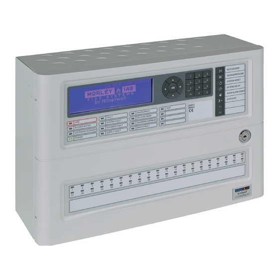
(996-220-00X-X) for more details. 1.2 Models The DX Connexion Series of Fire Alarm Control Panels, as shown below, are available in two enclosure sizes: the small enclosure for 1 loop and the medium enclosure for 2 or 4 loops. Each panel is capable of supporting up to 80 fire detection zones. -
Page 7: Warnings And Cautions
Dispose of used batteries responsibly and in accordance with any local regulations. See Appendix 4 Replacement of Components, Section 1.1 for further details. The DX Connexion Series range of panels has many features EN54-2 13.7 that, if used inappropriately, may contravene the requirements... -
Page 8: National Approvals
Morley-IAS 1.4 National Approvals This equipment must be installed and operated in accordance with these instructions and the appropriate national, regional and local regulations specific to the country and location of the installation. Consult with the appropriate Authority Having Jurisdiction (AHJ) for confirmation of the requirements. - Page 9 Morley-IAS In addition to the functions required by EN54-2, the panel supports a number of EN54 ancillary functions that are not required by EN54. These are outlined below: Ancillary Function Manual Section Auxiliary supply output 3.4.7 Peripheral loop output & supported devices 3.4.10...
-
Page 10: Unpacking
Morley-IAS 2 Unpacking The Dx Connexion Series of Fire Alarm Control Panels are simple to install, program and commis- sion if the recommended procedures described in this manual are followed. Before installing the Connexion Series Fire Alarm Control Panels, first ensure that all the equipment has been received. -
Page 11: Installation
Morley-IAS 3 Installation 3.1 Identification of Parts 3.1.1 Small Enclosure The small enclosure is used for the DXc1 Series panels. Figure 1 - Dimensions & Fixing Points - Small Enclosure 3.1.2 Medium Enclosure The medium enclosure is used for the DXc2 and DXc4 Series panels. -
Page 12: Installing The Enclosure (Surface Mount)
Morley-IAS 3.2 Installing the Enclosure (Surface Mount) Using the supplied key open the main door to access the enclosure interior. Disconnect the ribbon cable to the Display PCB at the Base PCB (this cable cannot be disconnected at the Display PCB). -
Page 13: Installing The Enclosure (Bezel Mount Option)
Morley-IAS 3.3 Installing the Enclosure (Bezel Mount Option) The bezel option is supplied as a separate item. The diagram below shows the typical bezel assembly. This arrangement is the same for all bezel options. The panel and bezel must be assembled together before fixing into the wall aperture. -
Page 14: Installing The Complete Assembly
Morley-IAS 3.3.2 Installing the Complete Assembly Offer the complete assembly to the recess to check for correct depth and clearance. Repeat this process until the correct depth and clearance have been achieved. Support the bezel / back box assembly in the desired position in the recess and mark the three fixing points in the panel (refer to surface mounting installation instructions for positions). -
Page 15: External Connections
3.4.3 Mains Power Input The DX Connexion Series Fire Alarm Control Panel receives power from a single-phase, 230V, 50Hz, mains supply. The mains input terminal block is located on the PSU-mounting bracket and in the same way for all DX Connexion Series variants. -
Page 16: Mains Cable Glands
Morley-IAS Open and lock out the main circuit breaker before connecting any wiring. Do not power the system until the installation is complete. Maintain separation between the 230V and the low voltage wiring. Do not route in the same trunking and keep apart in the enclosure. -
Page 17: Wiring/ Terminal Block Arrangement
Morley-IAS When the batteries are connected the panel performs a battery wiring integrity test. If this test fails BATTERY WIRING FAULT is displayed on the LCD. Check for poor battery wiring connections and remedy. If the batteries require charging the test is suspended for a period of up to 12 hours and re-applied. -
Page 18: Medium Enclosure Arrangement
Morley-IAS 3.4.4.3 Medium Enclosure Arrangement The diagram opposite shows the position for the 7Ah batteries in the medium-sized enclosure. Place the batteries with wiring terminals uppermost and push to the rear of the enclosure. The diagrams below show the position for the 12Ah and 17Ah batteries in the medium-sized enclosure. -
Page 19: Detection Loops
Morley-IAS 3.4.5 Detection Loops 3.4.5.1 General Information The control panel supports analogue detectors with a data transmission system. It provides power and communicates with the initiating devices over a two-wire circuit. All signalling loops communicate with the panel using a proprietary protocol. In some market regions the selection of protocol manufacturer is not available. -
Page 20: Loop Wiring Installation
Morley-IAS Maximum Loop Length MICC 18 AWG 16 AWG 14 AWG 1.5mm 2 km 1 km 1.5 km 2 km Table 2 - Maximum Loop Lengths Cable runs in excess of 2km (6400’) are not recommended. Otherwise, cable capacitance (Max. -
Page 21: Unused Loops
Morley-IAS Figure 13 - Loop Wiring with Isolators DO NOT loop the wiring under any terminals. Break the wire run to maintain supervision. It is recommended that short-circuit isolators be installed. Install the isolators at strategic points in the loop (i.e. zonal boundaries) to prevent an external short circuit from removing more than 32 addressable points from the system. -
Page 22: Sounder Circuits
Keep the connection as short as possible. Refer to Appendix 1 Specifications for a list of recommended cables. The DX Connexion Series Fire Alarm Control Panels have two power-limited and supervised sounder circuits, identified as sounder circuits S1 and S2. -
Page 23: Auxiliary Relay Outputs
Fault Output: EN54 Relay 1 is configured for failsafe operation as standard. The DX Connexion Series Fire Alarm Control Panels have three, unsupervised, relay outputs, with volt-free (dry contact) changeover contacts. These are assigned to Fault, Fire Alarm and User Programmable conditions respectively. -
Page 24: Digital Inputs
Figure 20- Monitored Circuit Input 3.4.10 RS485 Peripheral Link The DX Connexion Series Fire Alarm Control Panels can EN54-2: 8.8 be connected to a range of serial interface devices via the Integrity of RS485 peripheral loop. -
Page 25: Daisy Chain Style Installation
Morley-IAS 3.4.10.1 Daisy Chain Style Installation Form the peripheral RS485 link by taking wires from the A and B terminals to the A and B terminals of the next device on the link. Continue wiring to all the units to be connected to the link –... -
Page 26: Recommended Cable Routing
Morley-IAS 3.4.11 Recommended Cable Routing Cables should be routed within the enclosure in accordance with the following diagrams. Ensure that power-limited cables are routed separately from AC Mains and non power-limited cables. The diagrams below show typical arrangements for the DXc1 (small enclosure), DXc2 (medium enclosure) or DXc4 (medium enclosure) including recommended top-face knockouts. -
Page 27: Fitting Instructions
Morley-IAS 3.5.1 Fitting Instructions Ensure that all power is turned off and disconnected before proceeding From the rear of the front door, apply a consistent force to the removable part of the fascia located over the keyswitch-mounting hole - see illustration at right - until it has become fully detached from the door. -
Page 28: Slide-In Labels
If it does not, separate the keyswitch parts and repeat from step 4. 3.6 Slide-in Labels The DX Connexion Series of Fire Alarm Panels are provided with slide-in labels to denote the function of the LED Status Indicators and Keyboard Buttons. -
Page 29: Controls & Indications
Figure 29 - Typical Controls & Indications The illustration above shows the layout of controls and indications of the DXc2 and DXc4 fire control panels and is typical for all variants. For more detailed information refer to the DX Connexion Series User Manual (996-202-001-X). -
Page 30: Passcodes
Morley-IAS 4.1.2 Passcodes Up to ten USER LEVEL 2 passcodes can be programmed into the panel. The default passcode is 1234. The USER LEVEL 3 passcode is 9898. This cannot be changed. 4.1.3 List of Device Abbreviations The following table gives a list of the device (point) abbreviations shown on the LCD. -
Page 31: Programming
5 Programming 5.1 Introduction The basic operation and configuration parameters of the DX Connexion Series fire alarm control panels can be very easily programmed using the fastrack procedure which is presented to the user on powering up the panel for the first time. Refer to Section 5.2 Fastrack Panel Configuration for more details. -
Page 32: Text Entry
A new character may now be inserted. Use the alphanumeric keypad, as described above, to enter the required text. The DX Connexion Series panels have a library of 32 commonly-used words, listed in alphabetical order. Ten additional, site-specific words may be added to this library. - Page 33 Morley-IAS To display other word options that are not currently displayed, press the alphanumeric key which contains the letters nearest to the desired word - this will advance the list of words starting with the first letter on the pressed key, or the next letter if no words exist for the first letter, etc. (there are no words in the default list beginning with G, H, I, J, M, Q, U, X, Y or Z).
-
Page 34: Fastrack Panel Configuration
Morley-IAS 5.2 Fastrack Panel Configuration The DX Connexion Series of fire alarm control panels are provided with a built-in, fastrack configuration utility that is simple to use and quickly enables the provision of basic fire cover. The Fastrack process enables the basic configuration parameters to be programmed using a simple, step-by-step approach. - Page 35 Morley-IAS Step 4 Learn Loop(s) With the loop protocol set (where this step is required) the loop devices can now be configured using auto-learn, one loop at a time. If the panel has more than one loop of devices the total devices configured for each loop is listed before the auto-learn process can continue to the next loop, thereby, allowing the user to go back to the previous step, if desired.
-
Page 36: Programming Manually
Morley-IAS 5.3 Programming Manually The DX Connexion Series Fire Alarm Control Panels need to be at user access Level 3 before any commissioning functions can be carried out. Access Level 3 can be accessed the access Level 2 menu, as described below. -
Page 37: Recommended Step-By-Step Programming Guide
Morley-IAS 5.3.2 Recommended Step-by-Step Programming Guide The following is the recommended basic sequence for programming the panel manually. Step 1: Select the protocol (if option is available) and other general set-up options. Step 2: Learn the loops and program the parameters for the loop devices. -
Page 38: General Options
Morley-IAS 5.3.4 General Options From the Commission menu selecting ‘General Options’ displays the first five items in a list of configurable options. Use the keys to highlight the desired menu item. Use the to step down/ up one LCD page at a time. Press to confirm selection. -
Page 39: Loop
Morley-IAS Option Default Setting Description Title Options No. of Repeaters 0 - 16 Determines how many active (or addressed) repeaters are connected to the RS485 Communications link. 2nd Serial Port Disabled Disabled/ TPP TPP enables RS232 Interface PCB to be BAUD rate;... -
Page 40: Edit Devices
Morley-IAS 5.3.5.1 Edit Devices The information that can be programmed for the device depends on the type of device. The basic information available for all devices consist of: a 20-character location text, the assigned zone and the assigned disablement group. For input devices, such as monitor modules, the action and whether the input is latching can be programmed. -
Page 41: Edit Zone Assignment
Morley-IAS Refer to Section 5.1.3 Text Entry for details on text editing. When finished with editing text, press key to confirm the text entry/ changes and the LCD returns to the device edit screen. 5.3.5.1.2 Edit Zone Assignment With the zone number option shown, press the... -
Page 42: Table 7 - Input Parameter Options
Morley-IAS Process Action Latching Comments Pattern Logic No Action The input has no effect irrespective of its input condition. Fire Generates a fire alarm from the assigned zone. Bells will ring in accordance with the programmed patterns. -
Page 43: Output Controls
Morley-IAS 5.3.5.1.5 Output Controls Additional options are presented for output devices such as sounder and relay modules. Use the keys to view the available options, depending on the device type. Some of the possible options are given below: Ringing Pattern - select the ringing pattern to be associated with the ouput action. -
Page 44: Learn Devices
Morley-IAS The ‘Sounder’ and ‘Monitored’ options are normally pre-configured when the devices are learnt. These can be changed, however, to suit specific installation requirements. The ‘Sounder’ setting selects between a Sounder type output (Y) and a Relay type output (N). The ‘Monitored’... -
Page 45: Local Inputs
Morley-IAS Enter the appropriate loop number and press the key. Confirmation is requested to learn all devices on the loop. Press the key once more to start the learn process. To cancel, press the key. On completion, a summary of the differences is shown with a total figure. In this example, 23 new devices have been found (added), there are no devices found to be missing (removed) and there are no devices that have been found to change type (changed). -
Page 46: Input Action
Morley-IAS When entering this menu and with ‘Action’ selected, press the key to change the assigned action (‘No action’ is the default). The following options are selectable: Bomb Alert, Transparent action, Level 2 access, Class Change and Disable Group. These are listed as follows: 5.3.6.1... -
Page 47: Zone Number
Morley-IAS DO NOT USE WITH TIMERS. When the input is active then day mode will be on (active). Otherwise, day mode will be off (inactive). All input actions are non-latching. A indicates that this input action is supported on this input. An ... -
Page 48: Pattern Assignment
Morley-IAS In the example below the LCD displays the options available for Sounder 1 but these are available for any of the local outputs. Press the appropriate key to edit the assigned ringing pattern, whether the output can be pulsed, whether the output will turn on when the EVACUATE key is pressed and whether the output can be silenced when the SILENCE/RESOUND key is pressed. -
Page 49: Respond To Evacuate
Morley-IAS To change the selection either use the appropriate key to move the highlight and then press key to confirm the change. Alternatively, use the numeric keypad and press the ‘1’ or ‘2’ key to move the highlight and then press the key to confirm. -
Page 50: Zone Text
Morley-IAS 5.3.8 Zone Text A 20-character text description (including spaces) can be assigned to each of the 80 zones to clearly identify the location area of the fire alarm or fault. This text is shown on the access Level 1 LCD displays. - Page 51 Morley-IAS Using the numeric keypad, enter the pattern number and press the key. Alternatively, use keys to select a pattern; each press increments/ decrements the patterm number. When selected, the LCD presents the zone range associated with the pattern (1 - 80 is the default), in the...
-
Page 52: Zone Qualifiers
Morley-IAS In the example below logic pattern 5 has been configured to have different actions by zone, or range of zones, where a fire in zones 1 to 8 turn on the sounders, a fire in zones 9 to 11 pulse the sounders and a fire in zone 12 pulses the sounders for 30 secs and then turns them full on. -
Page 53: Panel State Inputs
Morley-IAS Select Delay at the ‘Enter New State’ prompt and press the key. With the current delay period highlighted (0 in the above screen) press the key to enter a new delay period. The lower part of the LCD now displays ‘Enter New Delay’ to allow a delay period to be entered. -
Page 54: Table 11 - Panel State Conditions
Morley-IAS Press the key to confirm the changed zone logic. A working example is given here of using a panel state input, with a pattern to use the on-board sounder number 1 to indicate when a pre-alarm condition has occurred, by turning on the output in a pulsing mode. -
Page 55: Detection Modes
Morley-IAS 5.3.10 Detection Modes One of three possible detection modes may be configured, as described in the table below. Only one of these modes can be configured at any one time. These can be configured to be manually activated or automatically activated using the 7-day timers. -
Page 56: Delayed (Stage 1/ Stage 2) Mode
Morley-IAS The ‘Night Levels’ option is highlighted by default. Using the numeric keypad press the ‘2’ key for the Select Modes option. Alternatively, use the key to move the highlight to the Select Mode option and press the key to select. The current settings are displayed; by default no detection mode is configured. -
Page 57: Verification Mode
Morley-IAS Press the key to change the time period for the first stage delay. A delay time of 60 seconds is pre- configured. This may be changed, is so desired, as follows. Press any of the numeric keys (0 - 9) to enter a new delay period. Use the numeric keypad to enter the new time. - Page 58 Morley-IAS Pressing the key opens the Verification period timers menu with the first delay period timer highlighted, by default, as below: Press the key to select Timer 1 (Verification period) or, using the numeric keypad, press the ‘2’ key to select the second period timer. Alternatively, use the...
-
Page 59: Sensitivity Mode
Morley-IAS 5.3.10.3 Sensitivity Mode The sensitivity of both smoke and temperature detectors can be adjusted by changing the threshold at which pre-alarm and fire alarm signals are generated. Increasing the threshold makes detectors less sensitive to smoke/heat and decreasing the threshold makes them more sensitive. -
Page 60: Night Threshold Levels
Morley-IAS The panel will not allow the threshold levels to be set at a level that would prevent recognition of a fire alarm condition. The pre-alarm level cannot be set greater than the fire alarm level. After editing, press the key to save the changes and exit back to the Verification Mode Timers screen. - Page 61 Morley-IAS Ensure that the system maintains safe fire alarm notification if thresholds are changed. The threshold level information presented depends on the protocol chosen. The above example is for Apollo Discovery devices. Enter the new alarm level threshold and press the key to confirm.
-
Page 62: 7-Day Timers
Morley-IAS 5.3.11 7-Day Timers The activation of the ‘Detection Mode’ can be scheduled to EN54-2: 7.11.2 operate at specific times. Manual or automatic EN54 Fourteen (14) separate active times can be scheduled and switching of Delays programmed in the panel. These can cross midnight to Outputs. - Page 63 Morley-IAS Press the key and the LCD returns to the Timer edit screen with the Finish ‘day’ field now highlighted. Edit this in the same way as with the Start day and time fields. After programming the timer press the key to exit and return to the list of programmable timers.
-
Page 64: Panel
Morley-IAS 5.3.12 Panel From the Commission menu press the ‘9’ key or, using the key to move the highlight to this option, and press the key, to select. The Panel menu has three options: LCD Contrast, Clock Offset and Wipe Memory. -
Page 65: Wipe Memory
Morley-IAS 5.3.12.3 Wipe Memory To return the panel to the factory default settings, press the ‘3‘ key to select the ‘Wipe Memory’ option. Alternatively, use the keys to highlight this option and press the key to select. The user is prompted as shown below. Press the key to start the wipe operation. -
Page 66: Programming Using The Pc Configuration Tool
Morley-IAS 5.4 Programming Using the PC Configuration Tool The DX Connexion Series of Fire Control Panels allows the programming of ALL configuration parameters including, for some markets, an option to select the SLC device manufacturer’s protocol. If using the Isolated USB to Serial... -
Page 67: Appendix 1 Specification
Morley-IAS Appendix 1 Specifications 1.1 Functional Specifications Specification Item Values Mechanical Small Medium Construction Mild steel sheet rear enclosure. ABS UL94-HB40 plastic front cover. All displays and controls are carried on the enclosure door. Dimensions (h x w x d) (mm) -
Page 68: Table 13 - Functional Specifications
Morley-IAS Specification Item Values Features Signalling Line Circuits DXc1 - 1 in-built loop driver panel DXc2 - 2 in-built loop driver panel DXc4 - 4 in-built loop driver panel Supports Analogue Addressable devices over a 2 wire combined power and data transmission loop. -
Page 69: Table 14 - Power Supply And Charger Specifications
Morley-IAS 2.2 Power Supply and Charger Specification Item Values Operating Voltage 230V 50Hz AC Voltage tolerance + 10% - 15% Incoming mains fuse 5A T5AH250V (20mm HRC anti-surge fuse in AC Mains TB) Base card input 25.0 to 23.0 V... -
Page 70: Recommended Cables
Morley-IAS 3 Recommended Cables All cables connected to the fire alarm control panel must be fire resistant cables. Shielded cable must be used for signalling loops and sounder circuits. The drain earth wire should be connected to a suitable earth bonding point at both ends (loops) or single end (sounders) of the cable. Earthing points are provided on the inside of the top face of the back box for this purpose. -
Page 71: Appendix 2 Battery Calculations
Morley-IAS Appendix 2 Standby Battery Calculations Quiescent Condition Alarm Condition Item Each Unit Total Amperes Each Unit Total Amperes (Units x Qty) (Units x Qty) Panel Type: DXc1 0.110 0.160 DXc2 0.110 0.160 DXc4 0.160 0.210 Sensor Current Loop 1... -
Page 72: Appendix 3 Maintenance
Morley-IAS Appendix 3 Maintenance 1.1 Maintenance Schedule Refer to national guidelines for recommended maintenance routines to be adopted. The recommendations of EN54-14 are outlined below. 1.1.1 EN54-14 Recommendations 1.1.1.1 Daily Attention The user should check the following: 1. The panel should indicate normal operation & if not the fault should be recorded in a logbook &... - Page 73 Morley-IAS Appendix 4 Replacement of Components 1 General All components used in the control panel have been chosen for high reliability and long life. The manufacturers’ data on the following items indicates that they may have a life expectancy of less than 15 years and so may need to be replaced in the future.
- Page 74 Morley-IAS 2.1 Base PCB The Base PCB is fitted in the panel and does not need to be removed for the installation of the fire alarm control panel. Each Base PCB variant, 1 Loop (kit PN 795-109) or 2 Loop (kit PN 795-110), is secured in the panel enclosure using four M3 SEM screws.
- Page 75 Replacement kit (PN: 795-124). 2.6 PSU The DX Connexion Series fire alarm control panels use two different PSUs with outputs of either 2A or 4A at 24V dc. The DXc1 panel variant uses the 2A version, while the DXc2 and DXc4 panel variants use the 4A version.
-
Page 76: Appendix 5 How To Flash Upgrade The Panel
PC Flash Program user interface reports the status of Flash upgrade process. On the PC start the DXc Flash Programmer. This can be done either by going to the ‘Start menu/All Programs/Morley-IAS by Honeywell’ and selecting the ‘DX Flash Programmer’ option, or by double- clicking the ‘DX Flash Programmer’ desktop icon. - Page 77 Morley-IAS The following screen is displayed: Click on ‘File’ and ‘Open...’ to display the following screen: Click the ‘Browse’ button to start the search for the required software upgrade ‘hex’ file. The approriate file will be shown once the correct folder location has been selected, as illustrated in the example below: With the folder containing the correct file, click on ‘Open...’...
- Page 78 Morley-IAS Click on ‘Comms’ menu, select ‘Port’ to check that the correct port is selected. If the USB to Serial Adapter Kit lead (PN: 020-891) is being used this will have been configured to use a specific port when the driver software was installed. This is a quick way of checking that the configured port has the black circle alongside.
- Page 79 Morley-IAS Step 3 Remove power from the panel and return the J1 jumper link to the DISABLE position. Re-apply mains and battery power. IT IS IMPORTANT THAT YOU DO THIS! It is now necessary to wipe the panel settings from the system menu before restoring them from the PC Tool.
-
Page 80: Appendix 6 Event Text Explained
Morley-IAS Appendix 6 Event Text Explained The table below provides a description of the meaning/ cause behind each possible event log entry. Event Text (English) Description/ Meaning Control Actions EVACUATE A 'Sound Alarms' button or digital loop input associated with the 'Evacuate' action has been activated. - Page 81 Morley-IAS Event Text (English) Description/ Meaning LEVEL 2 ACCESS START An input device associated with the 'Level 2 Access' action has been activated LEVEL 2 ACCESS END An input device associated with the 'Level 2 Access' action has returned from its activated state back to normal.
- Page 82 Morley-IAS Event Text (English) Description/ Meaning BAD DEVICE REPLY Persistent communication errors have occurred when communicating with a specific loop/ peripheral device. DEVICE LEVEL FAULT Generated if an analogue detection device is returning a very low analogue value. Check/ replace the device.
-
Page 83: Appendix 7 Peer-To-Peer Network Configuration
Appendix 7 Peer-to Peer Network Configuration 1 Introduction The DX Connexion Series of fire alarm control panels can form part of a fire alarm detection and system status indication network. Two network configuration options are available: loop or linear. Loop Configuration: each panel communicates independently with its immediate neighbours using a closed-loop topology. - Page 84 Morley-IAS To enter a panel ID (in the range 1 to 99) either use the numeric pushbuttons to enter the address or keys - the first press of either key will enter an ID of ‘0’ (not on network) which increments/ decrements with each press of the keys.
Need help?
Do you have a question about the DX CONNEXION and is the answer not in the manual?
Questions and answers
How to do the alert on sounders
To set up alerts on sounders for the MORLEY-IAS DX CONNEXION:
1. From the Commission menu, press the ‘4’ key to access the ‘Local Outputs’ menu.
2. Press the ‘4’ key again to display local outputs. Sounder 1 is highlighted by default.
3. Use keys ‘2’, ‘3’, ‘4’, or ‘5’ or navigation keys to select another output.
4. Press the appropriate key to edit:
- Assigned ringing pattern
- Pulse option
- Activation when EVACUATE key is pressed
- Whether output can be silenced using the SILENCE/RESOUND key
5. Assign each output to turn on based on logic rules depending on fire location.
Ensure sounder circuits (S1 and S2) are correctly connected with EOL resistors and blocking diodes.
This answer is automatically generated
How to clear a device change fault....?
To clear a device change fault on the MORLEY-IAS DX CONNEXION panel:
1. Reconfigure the system using the configuration tool to match the actual connected devices.
2. If necessary, wipe the memory to remove old configuration settings.
3. After reconfiguration or wiping the memory, perform a panel reset.
If the fault persists, the base-card PCB may need to be reprogrammed or returned to the factory.
This answer is automatically generated