Table of Contents
Advertisement
Available languages
Available languages
Quick Links
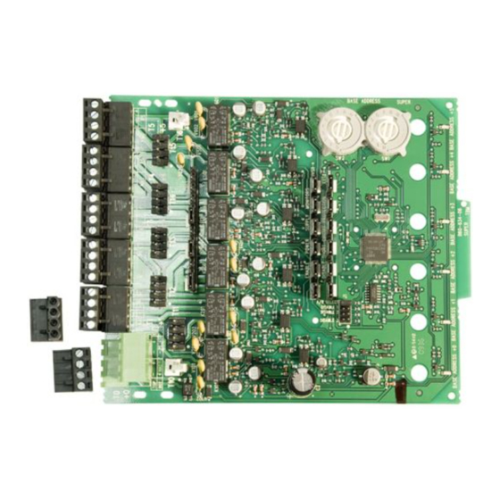
INSTALLATION AND MAINTENANCE INSTRUCTIONS
MI-SC6
Six Supervised Control Module
SPECIFICATIONS
Normal Operating Voltage:
Stand-By Current:
Alarm Current:
Temperature Range:
Humidity:
Dimensions:
Accessories:
Wire Gauge:
Maximum Monitored Output Circuit
Wiring Resistance:
Table 1:
CURRENT RATING
3A
2A
1A
.5A
BEFORE INSTALLING
This information is included as a quick reference installation
guide. Refer to the appropriate control panel installation manual
for detailed system information. If the modules will be installed in
an existing operational system, inform the operator and local au-
thority that the system will be temporarily out of service. Discon-
nect the power to the control panel before installing the modules.
This system contains static sensitive components. Always ground
yourself with a proper wrist strap before handling any circuits so
that static charges are removed from the body. The housing cabi-
net should be metallic and suitably grounded.
NOTICE: This manual should be left with the owner/user of
this equipment.
GENERAL DESCRIPTION
The MI-SC6 Six Supervised Control Module is intended for use in
an intelligent alarm system. Each module is intended for switch-
ing applications involving DC which require wiring supervision.
A common SLC input is used for all modules. Each module has
its own address. A pair of rotary code switches is used to set the
address of the first module from 01 to 94. The remaining mod-
ules are automatically assigned to the next five higher addresses.
Provisions are included for disabling a maximum of three unused
modules to release the addresses to be used elsewhere. Each mod-
ule also has panel controlled green LED indicators. The panel can
cause the LEDs to blink, latch on, or latch off.
Each module has terminals for connection to an external supply
circuit for powering devices on its Monitored Output Circuit.
Each supply must be power limited and its voltage/current limits
must be at or below those specified in Table 1.
There is a short circuit protection monitor for each module. This
is provided to protect the external power supply against short cir-
cuit conditions on the Monitored Output Circuit.
M450-01-00
15-32VDC
2.25 mA
35 mA (assumes all six relays have been switched
once and all six LEDs solid on)
-10°C to 55°C
10 to 93% Non-condensing
17.3cm H x 14.7cm W x 3.2cm D
Suitably grounded metallic cabinet
0.9mm2 - 3.25mm2
40 Ohms
MAXIMUM VOLTAGE
LOAD DESCRIPTION
30VDC
30VDC
30VDC
30VDC
Included:
Shipped on Board:
(1)
(6)
(6)
(3)
NOTE: Three shunts on Sync Generator MUST NOT be removed.
COMPATIBILITY REQUIREMENTS
To ensure proper operation, this module shall be connected to a
listed compatible control panel.
The MI-SC6 Module shall be mounted in a suitably grounded
Metallic Cabinet for EMC compliance.
1
Resistive
Resistive
Inductive (L/R = 2ms)
Inductive (L/R = 2ms)
(7) 1 × 4 Terminal Blocks
(2) 32mm Stand offs
(4) Screws
(5) Short Power Supply Jumpers
(2) Nuts
(1) Long Power Supply Jumper
Small shunt
Large shunts on Enable Power Supply Monitors
Large shunts on Disable Short Circuit Protection
Large shunts on Sync Generator
by Honeywell
Morley IAS Fire Systems
Charles Avenue
Burgess Hill, West Sussex, RH15 9UF
APPLICATION
Steady
Pulsing
Pulsing
Pulsing
(15) Large Shunts
(2) Small Shunts
(6) 47k Ohm End of Line Resistor
(2) EOL Relay
Connector Assembly
C0905-00
I56-2956-000
Advertisement
Table of Contents

Related Manuals for MORLEY-IAS MI-SC6


Summary of Contents for MORLEY-IAS MI-SC6
- Page 1 (1) Long Power Supply Jumper (6) 47k Ohm End of Line Resistor GENERAL DESCRIPTION The MI-SC6 Six Supervised Control Module is intended for use in an intelligent alarm system. Each module is intended for switch- (2) EOL Relay Connector Assembly ing applications involving DC which require wiring supervision.
-
Page 2: Wiring Notes
NOTE: SLC wiring is the top terminal block, notification appli- and appropriate wiring diagrams. ance/power supply is the bottom for terminal T0. All wiring to the MI-SC6 is done via terminal blocks. In order to properly make electrical connections strip approximately 5 WIRING NOTES mm of insulation from the end of wire, sliding the bare end of •... - Page 3 (figure 3 is typical) can be shared among multiple monitored out- A supply can be wired to be shared among multiple PCBs in the put circuits. If a supply is to be shared, between Monitored Out- same cabinet (figure 4 is typical). To share among multiple PCBs: put Circuits wired to a common PCB, use the short power supply use the long power supply jumpers (shown on page 1) to connect ei- jumpers shown on page 1.
- Page 4 Figure 4. Example of multiple boards sharing same external supply: – PCB 1 PCB 2 EXTERNAL POWER SUPPLY VIEW A-A C0203-00 NOTE: Supply is shared by Monitored Output Circuits +0 and +1 (on PCB 1) as well as +3, +4, and +5 (on PCB 2). Refer to figure 3 for typical Monitored Output Circuit wiring.
-
Page 5: Prima Dell'installazione
(5) Jumper di alimentazione piccole Jumper DESCRIZIONE GENERALE di alimentazione Il modulo di controllo con sei sistemi di supervisione MI-SC6 è (2) Dadi stato progettato per l’uso in sistemi d’allarme intelligenti. Ogni modulo è destinato ad applicazioni di switching tra cui CA, CC... - Page 6 Per garantire il corretto funzionamento, collegare questo modulo VISTA DALL'ALTO: al pannello di controllo di un sistema compatibile elencato. Il modulo MI-SC6 deve essere montato all’interno di un contenitore GENERATORE SINCRONIZZATO metallico collegato a massa per incontrare i requisiti di compati- bilità...
- Page 7 Tutte gli alimentatori, esterni al cabinet (in cui si trova il modulo Circuito D’uscita Supervisionato dello stesso modulo. La bobina MI-SC6) devono essere collegati al T0-T5 che sono connettori in- del relè di fine linea deve sempre essere collegata al PS+ (filo dicati per il cablaggio di campo.
- Page 8 Figura 3. Esempio di configurazione Circuito D’uscita Supervisionato Classe B, tipo Y con un singolo alimen- tatore condiviso da 2 Circuito D’uscita Supervisionato: (–) (–) ALIMENTAZIONE – ESTERNA INDIRIZZO DI RIFERIMENTO – 6 7 8 9 6 7 8 9 (–) (–) –...
-
Page 9: Especificaciones
(1) Puente de alimentación largo línea de 47k Ohmios DESCRIPCIÓN GENERAL El Módulo de Control MI-SC6 ha sido diseñado para su uso en un (2) Conector de Relé sistema de alarma inteligente. Cada módulo sirve para conectar de final de línea aplicaciones que tengan corriente continua (DC) y que requieran supervisión del cableado. - Page 10 (NAC) en la placa. correspondientes. NOTA: Guarde los puentes no utilizados para un posible uso en Todo el cableado del MI-SC6 se efectúa mediante bloques de terminales. Efectúe las conexiones eléctricas pelando unos 5 el futuro.
- Page 11 Todas las fuentes de alimentación externas a la cabina que albergan Se puede conectar una única fuente de alimentación de modo que el MI-SC6 deben estar conectadas a T0–T5, que son los conectores pueda ser compartida por varias placas PCB situadas en la misma adecuados para el cableado.
- Page 12 Figura 3. Ejemplo de configuración del CIRCUITO DE SALIDA SUPERVISADO en Clase B, Estilo Y con una única fuente de alimentación compartida por dos circuitos de salida supervisados: FUENTE DE ALIMENTACIÓN (–) (–) – EXTERNA DIRECCIÓN BASE – 6 7 8 9 6 7 8 9 (–) (–)
-
Page 13: Spezifikation
(1) Lange Steckverbinder (6) 47k Ohm Verbinder für ALLGEMEINES für Spannungsversorgung Abschlusswiderstand Das MI-SC6 Relais-Steuermodul wird in intelligenten Gefahren- meldeanlagen eingesetzt. Jedes Modul ist für das überwachte (2) Abschluss-Relais Schalten von Wechsel- oder Gleichspannung sowie Audiosignalen Baugruppe geeignet. Ein gemeinsamer Ringbus-Eingang wird für alle Module verwendet. - Page 14 Abbildung 1: Für den ordnungsgemäßen Betrieb muss das Modul an eine gee- DRAUFSICHT: ignete und kompatible Brandmelderzentrale angeschlossen werden. SYNC GENERATOR Das MI-SC6-Modul sollte für die Erfüllung der EMV-Richtlinie in einem geeigneten, geerdeten Metallgehäuse montiert werden ZUKÜNFTIGE FUNKTION VERDRAHTUNG EINSCHALTUNG SPANNUNGSÜBERWACHUNG HINWEIS: Die Verdrahtung muss gemäß...
- Page 15 T10 pin 1 T10 pin 4 T10 pin 2 +4 and +5 Alle externen Versorgungsspannungen (außerhalb des MI-SC6 Die Versorgungsspannung für mehrere Module in einem Gehäuse Montagegehäuses) sollten an die Anschlüsse T0-T5 angeschlos- kann mit einem Kabel weiterverbunden werden sen werden, die auch für den Anschluss der Ausgangsleitungen ( typische Darstellung in Abbildung 4 ).
- Page 16 Abbildung 3. Konfiguration der überwachten Steuerausgänge mit einer einzigen Spannungsversorgung für 2 Überwachte Steuerausgänge: EXTERNE SPANNUNGSVER- (–) (–) – SORGUNG MODUL ADRESSE – 6 7 8 9 6 7 8 9 (–) (–) – – SCHWARZ – STROMBEGRENZT OBEN VON T0 A/B AUSWAHL ABSCHALTUNG 1 UND ÜBERWACHT...
Need help?
Do you have a question about the MI-SC6 and is the answer not in the manual?
Questions and answers