Sign In
Upload
Manuals
Brands
MORLEY-IAS Manuals
Fire Alarms
DX CONNEXION
MORLEY-IAS DX CONNEXION Manuals
Manuals and User Guides for MORLEY-IAS DX CONNEXION. We have
1
MORLEY-IAS DX CONNEXION manual available for free PDF download: Product Manual
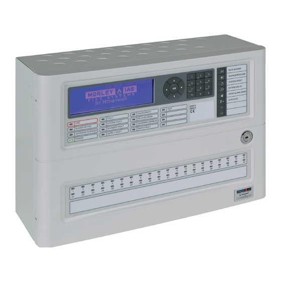
MORLEY-IAS DX CONNEXION Product Manual (84 pages)
Brand:
MORLEY-IAS
| Category:
Fire Alarms
| Size: 3.03 MB
Table of Contents
Table of Contents
2
1 Introduction
6
Notice
6
Models
6
Warnings and Cautions
7
National Approvals
8
EN54 Information
8
2 Unpacking
10
Table 1 - Packing Contents List
10
3 Installation
11
Identification of Parts
11
Small Enclosure
11
Medium Enclosure
11
Figure 1 - Dimensions & Fixing Points - Small Enclosure
11
Figure 2 - Dimensions & Fixing Points - Medium Enclosure
11
Installing the Enclosure (Surface Mount)
12
Position of Knockouts
12
Figure 3 - Position of Knockouts
12
Installing the Enclosure (Bezel Mount Option)
13
Wall Apertures
13
Figure 4 - Small & Medium Bezel Assemblies
13
Figure 5 - Recommended Aperture Sizes
13
Installing the Complete Assembly
14
External Connections
15
Introduction
15
Wiring Installation
15
Inspection and Testing
15
Mains Power Input
15
Mains Cable Glands
16
Battery Installation
16
Figure 6 - Mains Input Arrangement - All Panels
16
Wiring/ Terminal Block Arrangement
17
Small Enclosure Arrangement
17
Figure 7 - Battery Wiring/ Terminal Block Details
17
Figure 8 - Small Enclosure 7Ah Battery Installation
17
Medium Enclosure Arrangement
18
Battery Operation
18
Figure 9 - Medium Enclosure 7Ah Battery Installation
18
Figure 10- Medium Enclosure 12Ah Battery Installation
18
Figure 11 - Medium Enclosure 17Ah Battery Installation
18
Detection Loops
19
General Information
19
Cable Requirements
19
Loop Wiring Installation
20
Figure 12 - SLC Connections
20
Table 2 - Maximum Loop Lengths
20
Unused Loops
21
Figure 13 - Loop Wiring with Isolators
21
Figure 14 - Loop Wiring - Unused Loops
21
Sounder Circuits
22
Figure 15 - Sounder Circuit Connections
22
Figure 16 - Sounder Wiring
22
Auxiliary Relay Outputs
23
Auxiliary Supply Outputs
23
Figure 17 - Relay Circuit Connections
23
Figure 18 - Auxiliary Supply Circuit Connections
23
Digital Inputs
24
RS485 Peripheral Link
24
Figure 19 - Digital Input Circuit Connections
24
Figure 20- Monitored Circuit Input
24
Table 3 - List of Compatible Peripheral Devices
24
Daisy Chain Style Installation
25
Cable Screen - Earth Connections
25
Figure 21 - Typical RS485 - 'Daisy Chain' Wiring
25
Figure 22 - RS485 Screen - Earth Arrangement
25
Recommended Cable Routing
26
Keyswitch Option
26
Figure 23 - Dxc1 - Recommended Cable Routing
26
Figure 24 - Dxc2/4 - Recommended Cable Routing
26
Figure 25 - Keyswitch Location - Front View
26
Fitting Instructions
27
Recommended Procedure for Separation/Re-Assembly of Keyswitch
27
Figure 26 - Keyswitch Location - Rear View
27
Figure 27 - Keyswitch - Separated Assembly
27
Slide-In Labels
28
Figure 28- Slide-In Label Locations
28
4 Controls & Indications
29
User Control Levels
29
Access Level Definition
29
Figure 29 - Typical Controls & Indications
29
Passcodes
30
List of Device Abbreviations
30
Table 4 - Device Type Abbreviations
30
5 Programming
31
Introduction
31
Site Configuration Changes
31
Updating Software
31
Figure 30 - Location of Jumper Link J1 and PC Tool Connector
31
Text Entry
32
Alphanumeric Keypad
32
Display Format
32
Fastrack Panel Configuration
34
Programming Manually
36
Selecting the Commission Option
36
Overview of the Menu Structure
37
Recommended Step-By-Step Programming Guide
37
Table 5 - Menu Structure Overview
37
General Options
38
Loop
39
Table 6 - General Options
39
Edit Device Location Text
40
Edit Devices
40
Edit Group Disable Assignment
41
Edit Zone Assignment
41
Input Actions
41
Table 7 - Input Parameter Options
42
Output Controls
43
Learn Devices
44
Table 8 - Output Parameter Options
44
Local Inputs
45
Input Action
46
Table 9 - Input Actions - On-Board Inputs
46
Disablement Group
47
Local Outputs
47
Zone Number
47
Can Pulse
48
Pattern Assignment
48
Respond to Evacuate
49
Respond to Silence
49
Output Pattern Logic
50
Output Patterns
50
Zone Text
50
Delays
52
Table 10 - Zone Pattern Qualifiers
52
Zone Qualifiers
52
Panel State Inputs
53
Table 11 - Panel State Conditions
54
Detection Modes
55
Table 12 - Detection Modes
55
Delayed (Stage 1/ Stage 2) Mode
56
Verification Mode
57
Sensitivity Mode
59
Night Threshold Levels
60
7-Day Timers
62
Clock Offset - Drift Compensation
64
LCD Contrast
64
Panel
64
Wipe Memory
65
Programming Using the PC Configuration Tool
66
Retrieving Configuration Data
66
Sending Configuration Data
66
Figure 31 - Position of PC Tool Cable Connector
66
Appendix 1 Specification
67
Table 13 - Functional Specifications
68
Table 14 - Power Supply and Charger Specifications
69
Recommended Cables
70
Appendix 2 Battery Calculations
71
Appendix 3 Maintenance
72
Appendix 4 Replacement Parts
76
Appendix 5 How to Flash Upgrade the Panel
76
Appendix 6 Event Text Explained
80
Appendix 7 Peer-To-Peer Network Configuration
83
Advertisement
Advertisement
Related Products
MORLEY-IAS FW9003 Range
MORLEY-IAS MI-SC6
MORLEY-IAS Categories
Control Panel
Fire Alarms
Marine Equipment
Smoke Alarm
Accessories
More MORLEY-IAS Manuals
Login
Sign In
OR
Sign in with Facebook
Sign in with Google
Upload manual
Upload from disk
Upload from URL