
Related Manuals for MORLEY-IAS FW9003 Range


Summary of Contents for MORLEY-IAS FW9003 Range
- Page 1 FW9003 Range Document No. 996-174-000-1 Issue 01 installation manual This manual should not be left with the end user.
-
Page 2: Table Of Contents
ZX Fire Alarm Control Panels MORLEY-IAS Table of Contents INTRODUCTION ..........................1 ...........................1 OTICE .......................1 ARNINGS AND AUTIONS ......................2 ATIONAL PPROVALS EN54 I ........................2 NFORMATION UNPACKING..........................4 INSTALLATION ...........................5 ....................5 NSTALLING THE NCLOSURE 3.1.1 Removing the Chassis ....................5 3.1.2 Mounting the Enclosure to the Wall ................5 3.1.3... - Page 3 ZX Fire Alarm Control Panels 3.5.2 Loop Driver Cards....................... 29 3.5.2 Loop Driver Cards....................... 29 3.5.2.1 Voltage Selection ........................29 3.5.2.1.1 ZX1Se / ZX2Se Jumper Settings ..................29 3.5.2.1.2 ZX5Se Jumper Settings ....................30 3.5.3 485 / 232 Interface Cards ................... 30 3.5.3.1 Mounting the Card Directly to the Base Card ................31 3.5.3.2...
- Page 4 ZX Fire Alarm Control Panels MORLEY-IAS Table of Figures 1 – P – ZX1S / ZX2S ................6 IGURE ANEL IXING ENTRES 2 – P - ZX5S ..................6 IGURE ANEL IXING ENTRES 3 – E – ZX1S / ZX2S ..............7 IGURE...
-
Page 5: Introduction
ZX Fire Alarm Control Panels MORLEY-IAS 1 Introduction 1.1 Notice The material and instructions covered in this manual have been carefully checked for accuracy and are presumed to be correct. However, the manufacturer assumes no responsibility for inaccuracies and reserves the right to modify and revise this document without notice. -
Page 6: National Approvals
ZX Fire Alarm Control Panels CAUTION: A Lithium Battery is used for Data Retention. Replace only with the same or equivalent type. Contact the Service Organisation for Replacement CPU Card. The ZX1Se, ZX2Se and ZX5Se range of panels has many features, EN54-2 13.7 which if used inappropriately, may contravene the requirements of EN54... -
Page 7: Zx1S E / Zx2S E
ZX Fire Alarm Control Panels MORLEY-IAS ZX1Se, ZX2Se, ZX5Se & ZX10Se Power Supply EN54-4 Clause Functions Derive power supply from main power source Derive power supply from a standby battery source Charge and monitor the standby battery source Detect & signal power supply faults... -
Page 8: Unpacking
ZX Fire Alarm Control Panels 2 Unpacking The ZX1Se, ZX2Se, ZX5Se and ZX10Se Fire Alarm Control Panels are simple to install if the recommended procedures described in this manual are followed. Refer to the Commissioning Manual for details of how to program the system operation. Before installing the ZX1Se, ZX2Se, ZX5Se or ZX10Se Fire Alarm Control Panels, first ensure that all the equipment has been received. -
Page 9: Installation
ZX Fire Alarm Control Panels MORLEY-IAS 3 Installation 3.1 Installing the Enclosure Unlock the front door and remove the ferrite absorber and EOL resistor kits. Store these in a secure place for re-use later. If removing the chassis prior to installing the back box, proceed as described below. -
Page 10: Dimensions And Fixing Points
ZX Fire Alarm Control Panels For ZX10Se panels ensure both panels are re-connected as described above. Handle the chassis by holding the metalwork only. DO NOT lift it by holding the printed circuit boards or any parts on the circuit boards. 3.2 Dimensions and Fixing Points ISOLATE ELSEWHERE... -
Page 11: Identification Of Parts
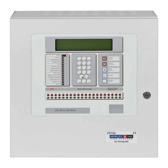
ZX Fire Alarm Control Panels MORLEY-IAS 3.3 Identification of Parts AC Mains Terminal Block with integral ISOLATE ELSEWHERE Fuse F1 T 2A H 250V ZX2Se Only Transformer and Filter Assembly SOUNDER OUTPUTS POWER Display / LIMITED RELAY 1 RELAY 2... -
Page 12: Cpu Board
(ZX10Se) plug-in loop driver modules for connection to the signalling detectors. The system can support addressable smoke detectors and loop devices through the use of loop driver boards. The options are as follows: Loop Device Manufacturer Loop Card Part No. Morley-IAS 795-072-100 System sensor 795-068-100 Hochiki... -
Page 13: External Connections
ZX Fire Alarm Control Panels MORLEY-IAS 3.4 External Connections BEFORE INSTALLATION: Refer to Ratings / Type label located on the inside of the panel. 3.4.1 Mains Power Input 3.4.1.1 ZX1Se / ZX2Se Arrangement The ZX1Se and ZX2Se Fire Alarm Control Panels receive power from either a 230V, 50Hz (or 120V, 60Hz-power supply ). -
Page 14: Zx10Se Arrangement
ZX Fire Alarm Control Panels Open and lock out the circuit breaker before connecting any wiring. Do not power the system until the installation is complete. Maintain separation between the 120/230V and the low voltage wiring. Do not route FS1 T 3.15A H 250V in same trunking and keep apart in the enclosure. -
Page 15: Battery Installation
ZX Fire Alarm Control Panels MORLEY-IAS 3.4.2 Battery Installation 3.4.2.1 General Introduction Refer to the Standby Battery Calculations (Section 4) for the size of the batteries required for a particular installation. Refer to Section 5.2.3 for a list of recommended batteries. -
Page 16: Zx5Se Arrangement
ZX Fire Alarm Control Panels 3.4.2.3 ZX5Se Arrangement Included in the packing is a battery cable kit. Use the cable included in FS1 T 3.15A H 250V this kit to connect the negative terminal of battery No.1 to the positive terminal of battery No.2. Connect the red wire from the Power Supply to the positive terminal of battery No.1. -
Page 17: Detection Loops
ZX Fire Alarm Control Panels MORLEY-IAS 3.4.3 Detection Loops The control panel supports analogue detectors with a digital, data transmission system. It provides power and communicates with the initiating devices over a two-wire circuit. Depending on protocol, it is possible for up to 1000 addressable input EN54-2 13.7... -
Page 18: Loop Wiring Installation
ZX Fire Alarm Control Panels For best results and system integrity: EN54-2 12.5.2 EN54 The detection loop circuit should be wired as a loop with short circuit Maximum of 32 isolators. This allows the system to still function in the event that a sensors / MCP’s section of the cable becomes short-circuited. -
Page 19: Emc Compliance
ZX Fire Alarm Control Panels MORLEY-IAS It is recommended that Short Circuit Isolators be installed. Install the isolators at strategic points in the loop (i.e. zonal boundaries) to prevent an external short circuit from removing more than 32 addressable points from the system. -
Page 20: Adding Loop Driver Cards
ZX Fire Alarm Control Panels 3.4.3.3 Adding Loop Driver Cards. An additional power cable is incorporated in the ZXSe range of fire panels. Connect the spare cable from the PSU wiring loom to either of the two connections shown on the Loop driver card, then use the supplied cable to ‘daisy chain’... -
Page 21: Sounder Circuits
ZX Fire Alarm Control Panels MORLEY-IAS 3.4.4 Sounder Circuits The ZX1Se and ZX2Se Fire Alarm Control Panels have two power-limited and supervised sounder circuits, identified as sounder circuits A and B. The ZX5Se Fire Alarm Control Panel has four power-limited and supervised sounder circuits, identified as sounder circuits A, B, C and D. -
Page 22: Wiring
ZX Fire Alarm Control Panels Any other devices connected to sounder outputs must be suppressed and polarized. Refer to Section 3.4.13 for a list of recommended cables. FACP Connections (made at Filter PCB) A (+) SOUNDER EOL (6k8) A (-) SOUNDER Typical Arrangement... -
Page 23: Auxiliary Relay Outputs
ZX Fire Alarm Control Panels MORLEY-IAS 3.4.5 Auxiliary Relay Outputs The ZX1Se, ZX2Se and ZX5Se Fire Alarm Control Panels have EN54-2 8.8 two unsupervised relay outputs, with volt-free (dry contact), EN54 changeover contacts. The ZX10Se has four of these relays. -
Page 24: Auxiliary Supply Output
ZX Fire Alarm Control Panels 3.4.6 Auxiliary Supply Output The ZX1Se, ZX2Se, ZX5Se and ZX10Se Fire Alarm Control Panels have a power-limited, unsupervised auxiliary (AUX O/P) 24V-output supply rated at 340mA maximum. This supply can be used to power Remote Annunciator (Repeater) units and other peripheral loop units or other signalling loop units. -
Page 25: Panel Networking / Graphics Pc Interface
ZX Fire Alarm Control Panels MORLEY-IAS 3.4.7 Panel Networking / Graphics PC Interface The Panel Network (Master to Slave panel) interface uses Port ‘C’ EN54-2 12.5 position on the base card. EN54 Integrity of A Master Panel (ZX5Se and ZX10Se only) can also be connected transmission paths: either to a Superior Master or to a Graphics PC using the Port ‘B’... -
Page 26: Peripheral Loop
ZX Fire Alarm Control Panels 3.4.8 Peripheral Loop The ZX1Se, ZX2Se, ZX5Se and ZX10Se Fire Alarm Control Panels EN54-2 12.5 can be connected to a range of serial interface devices via the EN54 peripheral loop. Integrity of transmission paths: The peripheral loop interface uses the Port D position on the base card. -
Page 27: Rs485 Wiring Arrangements
ZX Fire Alarm Control Panels MORLEY-IAS 3.4.9 RS485 Wiring Arrangements The following diagrams show the wiring arrangements for ‘daisy EN54-2 12.5 chain’ and ‘loop’ installations of the panel network and peripheral EN54 data bus interfaces. Integrity of transmission paths: Refer to Section 3.4.13 for a list of recommended cables. -
Page 28: Emc Compliance
ZX Fire Alarm Control Panels 3.4.9.3 EMC Compliance Connect Earth drain For EMC Compliance, fit wire of cables to nearest the Ferrite Absorber earth stud on inner, top supplied with the RS485 wall of back box Interface board around the - keep length as short as possible Peripheral (or Panel) Link... -
Page 29: Group Disable Input
ZX Fire Alarm Control Panels MORLEY-IAS 3.4.11 Group Disable Input The panel can be configured for an input device (loop call point / switch monitor or peripheral input) to act as a group-disable function. Refer to the Commissioning Manual for programming information. -
Page 30: Cable Routing
ZX Fire Alarm Control Panels 3.4.14 Cable Routing Cables should be routed within the enclosure in accordance with the following diagram. Ensure that power-limited cables are routed separately from AC Mains and non-power-limited cables. Sounder and RS485/RS232 SLC Circuits AC Mains AUX Power Power Limited Power Limited... -
Page 31: Installing Additional Equipment
ZX Fire Alarm Control Panels MORLEY-IAS 3.5 Installing Additional Equipment 3.5.1 General Introduction Always ensure that the mains and battery power supplies have been isolated before plugging or unplugging any of the internal circuit boards. Follow the specific instructions supplied with each item of additional equipment. -
Page 32: Zx2Se Arrangement
ZX Fire Alarm Control Panels 3.5.1.2 ZX2Se Arrangement RS485 RS485 or RS232 Interface Interface Card Card Loop Driver Modules Figure 28 – Positions for Additional Boards – ZX2Se 3.5.1.3 ZX5Se Arrangement Loop 5 Loop 4 Loop 3 Loop 2 Loop 1 + - E + - + - E + - + - E + -... -
Page 33: Loop Driver Cards
The loop voltage for each loop driver type is selected using the jumper link J1. The following table defines the position of J1 for each loop driver. Loop Driver J1 Position Morley-IAS (Part 795-072-100) System Sensor (Part 795-068-100) Apollo (Part 795-066 or 795-066-100) Hochiki (Part 795-058-005 or 795-058-105) Nittan (Part 795-044-001) Table 5 –... -
Page 34: Zx5Se Jumper Settings
The loop voltage for each loop driver type is selected using the jumper links J1 and J2. The following table defines the jumper position for each loop driver. Loop Driver J1 Position J2 Position Morley-IAS (Part 795-072-100) * Fitted System Sensor (Part 795-068-100) * Fitted Apollo (Part 795-066 or 795-066-100) -
Page 35: Mounting The Card Directly To The Base Card
ZX Fire Alarm Control Panels MORLEY-IAS 3.5.3.1 Mounting the Card Directly to the Base Card Use either the four fixing screws (M3 x 4-way 6mm) or the four nylon spacers (M3 x connector 30mm), supplied with the module, to mount the card onto the nylon spacers Base Card on the base card. -
Page 36: Printer Module (Zx5Se / Zx10Se Only)
ZX Fire Alarm Control Panels 3.5.4 Printer Module (ZX5Se / ZX10Se Only) 11 way The printer module is ribbon mounted to the reverse of Printer Interface cable the front panel door on the Card printer mounting plate. Control 12mm Nylon spacers Working from the rear of the Panel Door M3 x 20mm with... -
Page 37: Standby Battery Calculations
0.090 0.310 0.310 RS485 Module (EXP-004) 0.059 0.059 RS485 Module (EXP-004B) 0.025 0.025 RS232 Module (EXP-005) 0.059 0.059 Loop Driver Modules Morley-IAS (795-072-100) 0.012 0.12 System Sensor (795-068-100) 0.012 0.012 Apollo (795-066-100) 0.012 0.012 Hochiki (795-058-105) 0.021 0.021 Nittan (795-044-001) 0.035... -
Page 38: Table 8 - Current Ratingc
0.059 RS485 Module (EXP-004B) 0.025 0.025 RS232 Module (EXP-005) 0.059 0.059 Zone LED Expander (EXP-069-020 0r 0.014 0.019 EXP-069-060) Loop Driver Modules Morley-IAS (795-072-100) 0.012 0.012 System Sensor (795-068-100) 0.012 0.012 Apollo (795-066-100) 0.012 0.012 Hochiki (795-058-105) 0.021 0.021 Nittan (795-044-001) 0.035... -
Page 39: Sensor Current Calculations
ZX Fire Alarm Control Panels MORLEY-IAS The ZX5Se Fire Alarm Control Panel supervises and charges the two 12-volt batteries that make up the standby power source. Batteries are available commercially and should be of the sealed, lead-acid type. Suggested suppliers for the Batteries are Yuasa and Power-Sonic. -
Page 40: Maintenance
ZX Fire Alarm Control Panels 5 Maintenance 5.1 Maintenance Schedule The following Maintenance routine as recommended in EN54-14 should be adopted. 5.1.1 Daily Attention The user should check the following: The panel should indicate normal operation and if not the fault should be recorded in a logbook and reported to the servicing organization. -
Page 41: Replacement Of Components
ZX Fire Alarm Control Panels MORLEY-IAS 5.2 Replacement of Components All components used in the control panel have been chosen for high reliability and long life. The manufacturers’ data on the following items indicates that they may have a life expectancy of less than 15 years and so may need to be replaced in the future. -
Page 42: Specifications
ZX Fire Alarm Control Panels 6 Specifications 6.1 Functional Specifications Specification Item Values Enclosure 400mm wide, 400mm high, 135 mm deep Sealed to IP30. Weight 10 kg without batteries. 18.5 kg with 12Ah batteries fitted. Operating Temperature 0 C to +40 C Relative Humidity (non-condensing) Knockouts (20mm) - Page 43 ZX Fire Alarm Control Panels MORLEY-IAS Specification Item Values Enclosure 500mm wide, 500mm high, 183 mm deep. Sealed to IP30. Weight 19 kg without batteries. 38.8 kg with 24Ah batteries fitted. Operating Temperature 0 C to +40 C Relative Humidity...
-
Page 44: Power Supply And Charger
ZX Fire Alarm Control Panels 6.2 Power Supply and Charger Specification Item Values Input Voltage 230V 48-62Hz AC. (or 120V 60Hz AC ). Voltage tolerance + 10% - 15% Incoming mains fuse F1 T 2A H 250V 20mm (in AC Mains TB) Power supply card inputs 24VAC &... - Page 45 ZX Fire Alarm Control Panels MORLEY-IAS Specification Item Values Input Voltage 230V 48-62 Hz AC Voltage tolerance + 10% - 15% Incoming mains fuse FS1 T 3.15A 250V H 20mm - Chassis mounted. Power supply card input 16V AC (panel supply) from integral mains transformer.
-
Page 46: Appendix - Zx10Se Installation
ZX Fire Alarm Control Panels 7 Appendix - ZX10Se Installation 7.1 General The ZX10Se FACP has been designed to offer a solution to providing up to ten loops of fire detectors without the need to install the panels in different locations on site. Two ZX5Se FACPs are networked together within one large back box with provision for up to four 17Ah batteries to be fitted. -
Page 47: Dimensions And Fixing Points
ZX Fire Alarm Control Panels MORLEY-IAS 7.6 Dimensions and Fixing Points The ZX10Se FACP has the following physical dimensions and fixing positions: Figure 33 – Panel Fixing Centres – ZX10Se Installation Manual Document No. 996-174-000-1, Revision: 01 Page 43... -
Page 48: Identification Of Parts
ZX Fire Alarm Control Panels 7.7 Identification of Parts The ZX10Se comprises two ZX5Se FACPs, installed one above the other in an enclosure and networked together as shown below: AC Mains Termination Block - CPU card - upper unit Upper Display / Keyboard Upper unit Upper ZX5Se unit... -
Page 49: Internal Printer
ZX Fire Alarm Control Panels MORLEY-IAS 7.7.5 Internal Printer The ZX10Se FACP can be augmented by fitting an internal printer in the upper position only on the user interface door. Refer to Section 3.5.4 and to the Commissioning Manual for further information. -
Page 50: Mains Cable Glands
ZX Fire Alarm Control Panels 7.8.2 Mains Cable Glands Refer to Section 3.4.1.4 Mains Cable Glands for details of recommended cable glands. 7.9 Battery Installation Refer to Section 4 Standby Battery Calculation for calculating the battery backup size requirements for both ZX5Se panels used by the ZX10Se configuration to meet your particular site installation. -
Page 51: External Wiring Connections
ZX Fire Alarm Control Panels MORLEY-IAS 7.10 External Wiring Connections Refer to the following sections of this manual for information regarding the connection of detection loop cables, sounder circuits and other site installation wiring and cabling: Detection Loops – Section 3.4.3 Sounder Circuits - Section 3.4.4... -
Page 52: Installing Additional Equipment
ZX Fire Alarm Control Panels 7.12 Installing Additional Equipment Refer to Section 3.5 Installing Additional Equipment for relevant instructions on fitting loop driver cards, RS485 / RS232 interface cards, printer module (top panel only) or key switch option. 7.13 Maintenance Refer to Section 5 Maintenance for details relating to all ZX10Se FACP maintenance issues. - Page 53 ZX Fire Alarm Control Panels MORLEY-IAS Specification Item Values Operating Voltage 230V 50Hz AC. (or 120V 60Hz AC). Incoming mains fuse (x2) FS1 T 3.15A 250V H 20 mm - Chassis mounted. Power supply card input 16V AC (panel supply) from integral mains transformer.
- Page 54 ZX Fire Alarm Control Panels NOTES Page 50 Document No. 996-174-000-1, Revision: 01 Installation Manual...
Need help?
Do you have a question about the FW9003 Range and is the answer not in the manual?
Questions and answers