
Related Manuals for CyberPower HSTP3T60KE


Summary of Contents for CyberPower HSTP3T60KE
- Page 1 User’s Manual HSTP3T60/80/90/100/120/150 /200/250/300/400/500KE Cyber Power Systems, Inc. www.cyberpower.com...
-
Page 3: Safety Precautions
Safety Precautions Safety Precautions This manual contains information concerning the installation and operation of Tower UPS. Please carefully read this manual prior to installation. The Tower UPS cannot be put into operation until it is commissioned by engineers approved by the manufacturer (or its agent). Not doing so could result in personnel safety risk, equipment malfunction and invalidation of warranty. - Page 4 Safety Precautions Move & Install Keep the equipment away from heat source or air outlets. In case of fire, use dry powder extinguisher only, any liquid Danger extinguisher can result in electric shock. Do not start the system if any damage or abnormal parts founded.
-
Page 5: Battery Safety
Safety Precautions this manual. Battery Safety All the battery maintenance and servicing procedures involving internal access need special tools or keys and should be carried out only by trained personnel. WHEN CONNECTED TOGETHER, BATTERY TERMINAL VOLTAGE WILL EXCEED 400Vdc AND IS POTENTIALLY LEATHAL. - Page 6 Safety Precautions you may become blind if acid enters your eyes and your skin may be damaged by the acid. At the end of battery life, the battery may have internal short circuit, drain of electrolytic and erosion of positive/negative plates.
-
Page 7: Table Of Contents
Contents Contents Chapter 1 Product Introduction ....................1 1.1 System Configuration....................1 1.2 Power Module ......................1 1.3 Operation Mode ......................1 1.3.1 Normal Mode ......................1 1.3.2 Battery Mode ......................2 1.3.3 Bypass Mode ......................2 1.3.4 Maintenance Mode (Manual Bypass) ..............3 1.3.5 ECO Mode ....................... - Page 8 Contents 4.2.3 Switching the UPS into Normal Mode from Bypass Mode ........56 4.2.4 Switching the UPS into Maintenance Bypass Mode from Normal Mode ....56 4.2.5 Switching the UPS into Normal Mode from Maintenance Bypass Mode ....57 4.3 Battery Maintenance ....................57 4.4 EPO...........................
-
Page 9: Chapter 1 Product Introduction
Chapter 1 Product Introduction Chapter 1 Product Introduction 1.1 System Configuration The Tower UPS is configured by the following part: Power modules, Bypass & Monitoring module, and cabinet with manual Bypass switch. One or several battery strings should be installed to provide backup energy once the utility fails. The UPS structure is shown in Fig. -
Page 10: Battery Mode
Chapter 1 Product Introduction rectifier/charger derives power from the AC mains input source and supplies DC power to the inverter while simultaneously FLOAT or BOOST charging its associated backup battery. Manual Bypass Static Bypass Bypass Main Output Rectifier Inverter AC/DC DC/AC Battery Charge/... -
Page 11: Maintenance Mode (Manual Bypass)
Chapter 1 Product Introduction Manual Bypass Static Bypass Bypass Main Output Rectifier Inverter AC/DC DC/AC Battery Charge/ Discharge Fig.1-5 Bypass mode operation diagram 1.3.4 Maintenance Mode (Manual Bypass) A manual bypass switch is available to ensure continuity of supply to the critical load when the UPS becomes unavailable e.g. -
Page 12: Auto-Restart Mode
Chapter 1 Product Introduction Manual Bypass Static Bypass Bypass Main Output Rectifier Inverter AC/DC DC/AC Battery Charge/ Discharge Fig.1-7 ECO Mode operation diagram Note There is a short interruption time (less than 10ms) when transfer from ECO mode to battery mode, it must be sure that the interruption has no effect on loads. -
Page 13: Ups Outlook
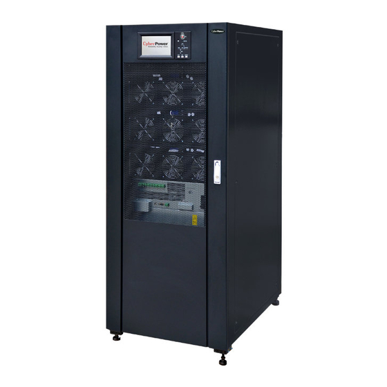
Chapter 1 Product Introduction 30kVA Except for 400kVA and 500kVA, Power unit Power unit all of the factory configureuration 50kVA Except for 400kVA and 500kVA, Power unit 1~10 Power unit all of the factory configureuration 1.4.2 UPS Outlook The UPS outlook is shown as Fig.1-8-1 to Fig.1-8-5. Fig.1-8-1 60KVA System outlook Fig.1-8-2 80-120KVA System outlook HSTP3T 60-500 KE User Manual... - Page 14 Chapter 1 Product Introduction Fig.1-8-3 150-200KVA System outlook-Front View Fig. 1-8-4 250-300KVA System outlook-Back View HSTP3T 60-500 KE User Manual...
- Page 15 Chapter 1 Product Introduction Fig. 1-8-5 400-500KVA System outlook-Back View HSTP3T 60-500 KE User Manual...
-
Page 16: Chapter 2 Installation Instruction
Chapter 2 Installation Instruction Chapter 2 Installation Instruction 2.1 Location As each site has its requirements, the installation instructions in this section are to act as a guide for the general procedures and practices that should be observed by the installing engineer. - Page 17 Chapter 2 Installation Instruction Fig.2-1 Room reserved for the cabinet(Unit:mm) Fig.2-2-1 Size of the 60KVA UPS (Unit : mm) HSTP3T 60-500 KE User Manual...
- Page 18 Chapter 2 Installation Instruction Fig.2-2-2 Size of the 80-120KVA for the cabinet(Unit:mm) Fig.2-2-3 Size of the 150-200KVA for the cabinet(Unit:mm) HSTP3T 60-500 KE User Manual...
- Page 19 Chapter 2 Installation Instruction Fig.2-2-4 Size of the 250-300KVA for the cabinet(Unit:mm) Fig.2-2-5 Size of the 400-500KVA for the cabinet(Unit:mm) HSTP3T 60-500 KE User Manual...
-
Page 20: Unloading And Unpacking
Chapter 2 Installation Instruction Ensure that the floor or installation support can bear the weight of the UPS, batteries, and battery racks. The weight of batteries and battery racks depends on the site requirements. The weight for the UPS cabinet is shown in Table 2.1 Table 2.1 Weight for the cabinet Capacity Weight... - Page 21 Chapter 2 Installation Instruction Fig.2-4 Disassemble the case 4. Remove the protective foam around the cabinet. Fig.2-5 Remove the protective foam 5. Check the UPS. (a) Visually examine if there are any damages to UPS during transportation. If any, contact to the carrier. (b) Check the UPS with the list of the goods.
-
Page 22: Positioning
Chapter 2 Installation Instruction 2.3 Positioning 2.3.1 Positioning Cabinet The UPS cabinet has two way of supporting itself: One is to support itself temporarily by the four wheels at the bottom, making it convenient to adjust the position of the cabinet;The other is by anchor bolts to support the cabinet permanently after adjusting the position of the cabinet. - Page 23 Chapter 2 Installation Instruction Fig.2-9-3 Supporting structure of 150kVA, 200kVA, 250kVA and 300kVA (Bottom view, unit:mm) Fig.2-9-4 Supporting structure of 400kVA and 500kVA (Bottom view, unit:mm) The steps to position the cabinet are as follows: 1. Ensure the supporting structure is in good condition and the mounting floor is smooth and strong.
-
Page 24: Battery
Chapter 2 Installation Instruction cabinet, which helps distribute the weight over a larger area. For instance, cover the floor with iron plate or increase the supporting area of the anchor bolts. 2.4 Battery Three terminals (positive, neutral, negative) are drawn from the battery unit and connected to UPS system. - Page 25 Chapter 2 Installation Instruction Fig.2-11-1 Cable Entry of 60kVA-200kVA Fig.2-11-2 Cable Entry of 250kVA-300kVA HSTP3T 60-500 KE User Manual...
- Page 26 Chapter 2 Installation Instruction Fig.2-11-3 Top cable Entry of 400kVA and 500kVA Fig.2-11-4 Bottom cable Entry of 400kVA and 500kVA HSTP3T 60-500 KE User Manual...
-
Page 27: Power Cables
Chapter 2 Installation Instruction 2.6 Power Cables 2.6.1 Specifications The UPS power cables are recommended in Table 2.2. Table 2.2 Recommended cables for power cables Contents 60kVA 80kVA 90kVA 100kVA 120kVA 150kVA Main Input Current(A) Main Input CableSection (mm²) Main Output Current(A) Main Output... -
Page 28: Specifications For Power Cables Terminal
Chapter 2 Installation Instruction Note The recommended cable section for power cables are only for situations described below: Ambient temperature:30℃. AC loss less than 3%,DC loss less than 1%,The length of the AC power cables are no longer than 50 m and the length of the DC power cables are no longer than 30 m. Currents listed in the table are based on the 380V system (Line-to-line voltage). -
Page 29: Circuit Breaker
Chapter 2 Installation Instruction 2.6.3 Circuit Breaker The circuit breakers (CB) for the system are recommended in Table 2.4. Table 2.4 Recommended CB Installed position 60kVA 80kVA 90kVA 100kVA 120kVA 150kVA Main input CB 125A/3P 160A/3P 160A/3P 250A/3P 250A/3P 320A/3P Bypass input CB 125A/3P 160A/3P... - Page 30 Chapter 2 Installation Instruction Fig.2-12-2 Connections terminals of 150kVA and 200kVA Fig.2-12-3 Connections terminals of 250kVA and 300kVA Fig.2-12-3 Connections terminals of 400kVA and 500kVA HSTP3T 60-500 KE User Manual...
-
Page 31: Control And Communication Cables
Chapter 2 Installation Instruction 3. Connect the protective earth wire to protective earth terminal (PE). 4. Connect the AC input supply cables to the Input terminal and AC output supply cables to the Output terminal. 5. Connect the Battery cables to the Battery terminal. 6. -
Page 32: Dry Contact Interface
Chapter 2 Installation Instruction Fig.2-13-2 Dry contact &communication interface of 400kVA and 500kVA 2.7.1 Dry Contact Interface Dry contact interface includes port J2-J11 and the functions of the dry contact are shown in Table 2.5. Table 2.5 Functions of the port Port Name Function... - Page 33 Chapter 2 Installation Instruction Output dry contact (Normally open), function is settable. J8-2 BAT_LOW_ALARM_NO Default: Low battery alarming J8-3 BAT_LOW_ALARM_GND Common terminal for J8-1 and J8-2 Output dry contact, (Normally closed) function is settable. J9-1 GENERAL_ALARM_NC Default: Fault alarming Output dry contact, (Normally open) function is settable. J9-2 GENERAL_ALARM_NO Default: Fault alarming...
- Page 34 Chapter 2 Installation Instruction Remote EPO Input Port J4 is the input port for remote EPO. It requires shorting NC and +24V and disconnecting NO and +24V during normal operation, and the EPO is triggered when opening NC and +24V or shorting the NO and +24V.
- Page 35 Chapter 2 Installation Instruction BCB Input Port The default function of J6 and J7 are the ports of BCB. The port diagram is shown in Fig.2-17, and description is shown in Table 2.9. +24V +24V +24V Fig.2-17 BCB Port Table 2.9 Description of BCB port Port Name Function...
- Page 36 Chapter 2 Installation Instruction Port Name Function J8-3 BAT_LOW_ALARM_GND Common terminal General Alarm Output Dry Contact Interface The default function of J9 is the general alarm output dry contact interface. When one or more warnings are triggered, an auxiliary dry contact signal will be active via the isolation of a relay.
-
Page 37: Communication Interface
Chapter 2 Installation Instruction Table 2.12 Utility failure warning dry contact interface description Port Name Function Mains failure warning relay(normally closed) will J10-1 UTILITY_FAIL_NC be open during warning Mains failure warning relay (normally open) will J10-2 UTILITY_FAIL_NO be closed during warning J10-3 UTILITY_FAIL_GND Common terminal... -
Page 38: Chapter 3 Lcd Panel
Chapter 3 LCD Panel Chapter 3 LCD Panel 3.1 Introduction This chapter introduces the functions and operator instructions of the operator control and display panel in detail, and provides LCD display information, including LCD display types, detailed menu information, prompt window information and UPS alarm information. 3.2 LCD panel for Cabinet The structure of operator control and display panel for cabinet is shown in Fig.3-1. - Page 39 Chapter 3 LCD Panel Indicators State Description Steady Rectifier normal for all modules green Flashing Rectifier Rectifier normal for at least one module, mains normal green indicator Steady red Rectifier fault Flashing red Mains abnormal for at least one module Rectifier not operating Steady Battery charging...
-
Page 40: Control And Operation Keys
Chapter 3 LCD Panel Continuous alarm When system has serious faults (for example: fuse or hardware fault) 3.2.2 Control and Operation Keys Control and operation keys include four keys, which are used together with LCD touch screen. The functions description is shown in Table 3.3. Table 3.3 Functions of Control and operation keys Function Key Description... - Page 41 Chapter 3 LCD Panel Icon Description Main input parameter(voltage, current, PF, frequency) History log, system information Function setting (display calibration, password setting, time setting, date format, communication protocol and language setting), system setting (used only for manufacturer) Battery data, battery parameter setting (used for service engineer) Test (battery self-test, battery maintenance) Functional keys used by service staff (fault clear, history log clear, mute on or off, manual transfer to bypass or escape from bypass), user setting...
-
Page 42: System Information Window
Chapter 3 LCD Panel Home page consists of Status bar, Information display, warning information and main menu. Status bar The Status bar contains the model of the product, capacity, operational mode, and the number of the power module and the time of the system. ... -
Page 43: Menu Window
Chapter 3 LCD Panel 16:15 Current Time (format: 24 hours, hour :minute) Normal: UPS in normal condition (Status) Normal, alarm, fault Alarm: UPS has general alarm, such as AC input fault Fault: UPS fuse or hardware fault 3.4 Menu Window The Menu Window displays the menu name of data window, while the data window displays the related contents of selected menu in menu window. - Page 44 Chapter 3 LCD Panel Menu name Menu item Meaning Settings MONTH-DATE-YEAR and YEAR-MONTH-DATE Date format set formats can be selected Date & Time Date/Time set Language set User can set the language Communication set Control password 1 User can modify control password 1 This test will lead to the battery being partly Battery discharged to activate battery until battery voltage is...
- Page 45 Chapter 3 LCD Panel The Cabinet comprises sectors of title, information display, version running status, information display and submenu. The sectors are described as follows. Title Display the information of the selected submenu. Running status The squares shown on the mini current path represent the various UPS power paths and show the current UPS operating status.
- Page 46 Chapter 3 LCD Panel Submenu Name Contents Meaning Power factor Phase voltage Phase current Bypass Bypass frequency Power factor Phase voltage Phase current Output Output frequency Power factor Sout: Apparent Power Pout: Active Power Load Qout: Reactive power kVar Load (The percentage of the UPS load) %...
- Page 47 Chapter 3 LCD Panel Information display Display information of each submenu. Power unit information The users can choose the power unit to browse the information in the “Information display” sector. Colors of the square on the mimic current path represent the various power unit paths and show the current operating status.
- Page 48 Chapter 3 LCD Panel Submenu Contents Meaning Name Input phase current of selected module Input frequency of selected module Input power factor of selected module Output phase voltage of selected module Output phase current of selected module Output Output frequency of selected module Output power factor of selected module Load voltage of selected module Load (The percentage of the power module selected)
- Page 49 Chapter 3 LCD Panel The submenus are listed on the right side of the Setting page. Users can enter each of the setting interfaces by touching the relevant icon. The submenus are described in details below in Table 3.9. Table 3.9 Description of each submenu of Setting Submenu Contents Meaning...
-
Page 50: Event List
Chapter 3 LCD Panel Submenu Contents Meaning Name Auto Boost Period Setting the auto boost period Auto Maintenance Setting the period for auto maintenance Discharge Period discharge Setting the system mode: Single , parallel, SERVICE System Mode Single ECO, parallel ECO, LBS, parallel Configure the rated RATE For the factory use... - Page 51 Chapter 3 LCD Panel EPO-Set Emergency Power Off Valid Inverter capacity is less then the load Module On Less-Set capacity Module On Less-Clear Incident above disappears Generator Input-Set Generator as the Ac Input Source Generator Input-Clear Incident above disappears Utility Abnormal-Set Utility (Grid) Abnormal Utility Abnormal-Clear Incident above disappears...
- Page 52 Chapter 3 LCD Panel N# Power Module Output Over Load Output Overload-Set Incident above disappears Output Overload-Clear N# Power Module Inverter Over Load Timeout Inverter Overload Tout-Set Incident above disappears INV Overload Tout-Clear N# Power Module Inverter Over Temperature Inverter Over Temp.-Set Incident above disappears Inverter Over Temp.-Clear Inhibit system transfer from bypass to UPS...
- Page 53 Chapter 3 LCD Panel Input Curr Unbalance-Set Input current is not balance Input Curr Unbalance-Clear Incident above disappears DC Bus Over Volt-Set DC bus over Voltage DC Bus Over Volt-Clear Incident above disappears REC Soft Start Fail-Set Rectifier soft start fails REC Soft Start Fail-Clear Incident above disappears Relay Connect Fail-Set...
- Page 54 Chapter 3 LCD Panel Log Clear Manually clear History log Load On UPS Inverter feeds load Load On Bypass Bypass feeds load No Load No load Battery Boost Charger is working in boost charging mode Battery Float Charger is working in float charging mode Battery Discharge Battery is discharging Battery...
- Page 55 Chapter 3 LCD Panel breaker open”, “Byp Sequence Err” and “Ip Neutral Lost”. If there is any relevant alarm, first clear this alarm. 1. Then check and confirm if the bypass frequency displayed on the LCD are within the setting range. Note that the rated frequency are respectively specified by “Output Frequency”.
- Page 56 Chapter 3 LCD Panel 2. If this alarm is true, measure the actual output current to confirm if the displayed value is correct. Disconnect non-critical load. In parallel system, this alarm will be triggered if the load is severely imbalanced. Inverter Overload N# Power Module Inverter Over Load Timeout.
- Page 57 Chapter 3 LCD Panel shuts down rectifier and inverter, and there’s on inverter output. Manual Boost Manually force the Charger work in boost charge mode. Charge Manual Float Manually force the charger work in float charge mode. Charge UPS Locked Forbidden to shutdown UPS power module manually.
- Page 58 Chapter 3 LCD Panel Please check if ambient temperature is too high. The difference of input current between every two phases is over 40% of rated current. Input Curr Please check if rectifier’s fuses, diode, IGBT or PFC diodes are Unbalance broken.
-
Page 59: Operate(150-500Kva)
Chapter 3 LCD Panel Working life of bypass fans is expired, and it’s recommended that Bypass Fan the fans are replaced with new fans. It must be activated via Expired software. Working life of capacitors is expired, and it’s recommended that Capacitor Expired the capacitors are replaced with new capacitors. - Page 60 Chapter 3 LCD Panel ESC Mute Transfer to Bypass Operate menu Fig.3-11 The “Operate” menu includes FUNCTION BUTTON and TEST COMMAND. The contents are described in details below. FUNTION BUTTON Clear/Restore Buzzing Mute or Restore buzzing of the system by touching the icon ...
-
Page 61: Scope(150-500Kva)
Chapter 3 LCD Panel By touching the icon , the system transfers to the Battery mode. Thisfunction is used for maintaining the battery, which requires the normalityof the bypass and minimum capacity of 25% for the battery. Battery Boost By touching the icon , the system starts boost charging. -
Page 62: Chapter 4 Operations
Chapter 4 Operations Chapter 4 Operations 4.1 UPS Start-up 4.1.1 Start in Normal Mode The UPS must be started up by commissioning engineer after the completeness of installation. The steps below must be followed: 1. Ensure all the circuit breakers are open. 2. -
Page 63: Procedure For Switching Between Operation Modes
Chapter 4 Operations Note When the system starts, the stored setting will be loaded. Users can browse all incidents during the process of the starting up by checking the menu Log. Users can check the information of the power unit by the keys in the front of it. 4.1.2 Start from Battery The start from battery is referring to battery cold start. -
Page 64: Switching The Ups Into Normal Mode From Bypass Mode
Chapter 4 Operations 2. Press and hold the BYP key on the operator control panel for longer than two seconds and the system transfers to bypass mode. This needs to enable the switch behind the front door. As shown in Fig. 4-2. Enable the switch Zoom in A area Fig. -
Page 65: Switching The Ups Into Normal Mode From Maintenance Bypass Mode
Chapter 4 Operations bypass breaker, so need to used external circuit breakers). The maintenance bypass supplies power to loads. Note 150kVA - 300kVA only have a manual bypass breaker. In manual bypass mode (The manual bypass supplies power to loads), dangerous voltages are present on terminal and internal copper bar. - Page 66 Chapter 4 Operations (a) 60kVA – 120kVA (a) 150kVA – 500kVA Fig.4-3 Battery maintenance 2. Auto discharging. The system cans maintenance the battery automatically when the setting is done. The setting procedures are as follows. (a) Enable battery auto discharge. Enter the “CONFIGURE” page of the menu Setting, tick the “Battery Auto Discharge”...
- Page 67 Chapter 4 Operations 6480 Fig.4-4 Setting period for battery auto discharge Warning The load for the auto maintenance discharge should be 20%-100%,if not, the system will not start the process automatically. 4.4 EPO The EPO button located in the operator control and display panel (with cover to avoid disoperation, see Fig.4-5) is designed to switch off the UPS in emergency conditions (e.g., fire, flood, etc.).To achieve this, just press the EPO button, and the system will turn off the rectifier, inverter and stop powering the load immediately (including the inverter and bypass output),...
-
Page 68: Installation Of Parallel Operation System
Chapter 4 Operations (a) 60kVA – 120kVA (b) 150kVA – 500kVA Fig. 4-5 EPO Button 4.5 Installation of Parallel Operation System The UPS system can have three cabinets in parallel. Two UPS cabinets are connected as is shown in Fig.4-6. HSTP3T 60-500 KE User Manual... - Page 69 Chapter 4 Operations Power Supply UPS1 UPS2 Output Power Supply Load Connected Fig. 4-6 Parallel diagram The parallel interfaces of 60kVA-300kVA are located in the front panel of the cabinet, and the 400kVA -500kVA are located inside the cabinet, open the panel can see. The parallel terminal is shown in Fig.
- Page 70 Chapter 4 Operations (b) The parallel interfaces of 4000kVA and 500kVA Fig. 4-7 Location of the Parallel board The control cables for the parallel operation must be connected with all single devices to form a closed loop, as is shown in Fig.4-8. Fig.
-
Page 71: Chapter 5 Maintenance
Chapter 4 Operations Chapter 5 Maintenance This chapter introduces UPS maintenance, including the maintenance instructions of power module and monitoring bypass module and the replacement method of dust filter. 5.1 Precautions Only maintaining engineers can maintain the power module and monitoring bypass module. -
Page 72: Maintaining Monitor Unit And Bypass Unit For 150Kva And 300Kva
Chapter 5 Maintenance After the completion of maintenance, insert power unit and tighten the screws on both sides of the power unit. One by one to turn on the output breaker, bypass input breaker, input breaker and battery breaker. 7) After 2 minutes, the bypass indicator LED goes green, and the load is powered through maintenance bypass and static bypass. -
Page 73: Battery Setting
Chapter 5 Maintenance 9) Turn off the maintenance bypass breaker. 10) After 30S, the rectifier starts, the rectifier indicator LED goes green, and then inverter starts. 11) After 60S, the system transfers to Normal mode. 5.4 Battery Setting The setting of battery needs to be done after the first time of powering off or any changes done on the batteries. -
Page 74: Battery Capacity Setting
Chapter 5 Maintenance battery is 40, it means that there are 40 blocks of batteries and both the positive and negative are 20 blocks of batteries. In the case of cell battery of 2V (usually with large capacity) is used, battery number should be the same as the block battery. -
Page 75: Charging Current Percent Limit
Chapter 5 Maintenance For Lead-Acid battery, the cell voltage is suggested to set to 1.65V/cell at 0.6C, and set to 1.75V at 0.15C For the LFPB battery, the cell voltage is suggested to set to 2.7V/cell at both 0.6C and 0.15C. -
Page 76: Warnings For Battery And Environment Temperature Overheat
Chapter 5 Maintenance The system discharges the battery when the reaching the Auto maintenance discharge period. This function should be enabled by checking the AutoMaint (Rate Setting->SysCodeSetting1) through the monitoring software, as shown in Fig.5-4. Fig.5-4 Enable the Auto maintenance Discharge period The EOD voltage of Auto maintenance Discharge is 1.05 times of the normal EOD voltage. -
Page 77: Chapter 6 Product Specification
Chapter 6 Product Specification Chapter 6 Product Specification This chapter provides the specifications of the product, including environmental characteristics mechanical characteristics and electrical characteristics. 6.1 Applicable Standards The UPS has been designed to conform to the following European and international standards: Table 6.1 Compliance with European and International Standards Item... -
Page 78: Electrical Characteristics
Chapter 6 Product Specification Model Unit 150kVA 200kVA 250kVA 300kVA Mechanical Dimension 650*960*1600 650*960*1600 650*970*2000 650*970*2000 (W*D*H) Weight color Black Protection Level, IP20 (IEC60529) Model Unit 400kVA 500kVA Mechanical Dimension 1300*1100*2000 1300*1100*2000 (W*D*H) Weight color Black Protection Level, IP20 (IEC60529) Table 6.4 Mechanical Characteristics for Power Module Model Unit... -
Page 79: Electrical Characteristics (Inverter Output)
Chapter 6 Product Specification Ripple voltage ≤1 % Ripple current ≤5 % Equalized 2.4V/cell(selectable from : 2.30V/cell~2.45V/cell) VRLA charge voltage Constant current and constant voltage charge mode 1.65V/cell(selectable from: 1.60V/cell~1.750V/cell) @0.6C discharge current Final 1.75V/cell (selectable from: 1.65V/cell~1.8V/cell) V/cell @0.15C discharge current discharging voltage (VRLA)... -
Page 80: Efficiency
Chapter 6 Product Specification Current rating of 1.7×In 1.7×In neutral cable Rated frequency 50/60 50/60 Switch time (between Synchronized transfer: 0ms bypass and inverter) Settable, default -20%~+15% Bypass voltage range Up limited: +10%, +15%, +20%, +25% Down limited: -10%, -15%, -20%, -30%, -40% Bypass frequency Settable, ±1Hz, ±3Hz, ±5Hz range...
Need help?
Do you have a question about the HSTP3T60KE and is the answer not in the manual?
Questions and answers