Advertisement
Instruction Manual
Form 1243
December 2015
630 Series Regulators and Relief Valves
Introduction
Scope of Manual
This Instruction Manual provides operating, installation,
maintenance and parts information for the 630 Series
regulators and relief valves.
Description
The 630 Series consists of self-operated, spring
loaded Type 630 Big Joe
Type 630R relief valves, which are designed for
maximum inlet pressures to 1500 psig / 103 bar and
outlet pressures from 3 to 500 psig / 0.21 to 34.5 bar.
Installation
WaRnIng
!
Personal injury, property damage,
equipment damage or leakage due to
escaping gas or bursting of pressure-
containing parts may result if this
regulator is overpressured or is installed
where service conditions could exceed
the limits given in Specifications
section, Tables 1 through 3 or where
conditions exceed any ratings of the
adjacent piping or piping connections.
To avoid such injury or damage, provide
pressure-relieving or pressure-limiting
devices (as required by the appropriate
code, regulation or standard) to prevent
service conditions from exceeding
those limits.
pressure regulators and
®
www.fisherregulators.com
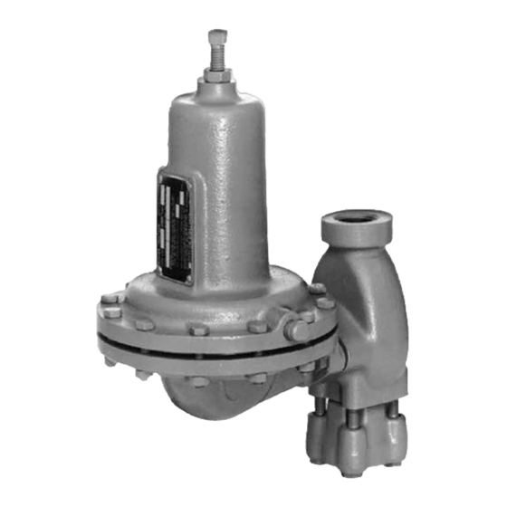
W1934
Figure 1. Spring-Loaded Type 630 Regulator
additionally, physical damage to the
regulator could cause personal injury or
property damage due to escaping gas.
To avoid such injury or damage, install
the regulator in a safe location.
Before installing, inspect the unit for any damage and
any foreign material. The regulator or relief valve may
be mounted in any position, however, ensure that the
flow direction corresponds with the direction of the
arrow on the nameplate. Apply a good grade of pipe
compound to the male threads of the pipeline.
630 Series
Advertisement
Table of Contents

Related Manuals for Emerson Fisher 630 Series


Summary of Contents for Emerson Fisher 630 Series
- Page 1 630 Series Instruction Manual Form 1243 December 2015 630 Series Regulators and Relief Valves Introduction Scope of Manual This Instruction Manual provides operating, installation, maintenance and parts information for the 630 Series regulators and relief valves. Description The 630 Series consists of self-operated, spring loaded Type 630 Big Joe pressure regulators and ®...
-
Page 2: Specifications
630 Series Specifications The Specifications section lists the specifications for the 630 Series constructions. Pressure Registration Available Configurations Internal Type 630: Spring-loaded reducing regulators Type 630R: Spring-loaded relief valves Spring Case Vent 1/4 NPT Body Size 1 and 2 in. / DN 25 and 50 Material Temperature Capabilities Standard: -20 to 180°F / -29 to 82°C End Connection Style... - Page 3 630 Series Table 1. Maximum Allowable Inlet Pressures and Pressure Drops MaXIMUM allOWaBlE PRESSURE DROP MaXIMUM allOWaBlE nylon (Pa) ORIfICE SIzE InlET PRESSURE Polytetrafluoroethylene fluorocarbon (fKM) Disk nitrile (nBR) Disk (PTfE) Disk psig psig psig psig 1/8 and 3/16 3.2 and 4.8 1500 1500 41.4...
-
Page 4: Principle Of Operation
630 Series 46A2977 46A2976-A A2526-1 A2525-1 InlET PRESSURE InlET PRESSURE OUTlET PRESSURE OUTlET PRESSURE aTMOSPHERIC PRESSURE aTMOSPHERIC PRESSURE Figure 2. Type 630 Regulator Operational Schematic Figure 3. Type 630R Relief Valve Operational Schematic adjusting Spring-loaded Regulators WaRnIng and Relief Valves To avoid the consequences of over- Loosen the hex nut (key 2, Figures 4, 5 and 6) atop tightening the spring in spring-loaded... -
Page 5: Maintenance
630 Series the valve open. When the outlet pressure exceeds the CaUTIOn set pressure, the diaphragm moves to compress the spring and the lever closes the valve until the outlet If step 1 is omitted and the body and pressure returns to set pressure. inlet adaptor are separated, take care to avoid pinching fingers between the body Type 630R Relief Valves... -
Page 6: Replacing The Diaphragm
630 Series 0X00119-F Figure 4. Spring-Loaded Type 630 Regulator - Low Pressure Construction 9. Be certain the lever (key 14) engages the 5. Unscrew cap screw (key 6) from connector valve carrier. head assembly (key 12) and disassemble the diaphragm assembly. 10. -
Page 7: Parts Ordering
630 Series 10 30 17 18 19 20 21 22 CB2197-E Figure 5. Spring Loaded Type 630 Regulator - High Pressure Construction Parts list 8. To ensure proper slack in the diaphragm, tighten the spring case cap screws finger-tight only. Compress the spring slightly with the adjusting note screw then complete the tightening of the spring... - Page 8 630 Series 22 21 20 19 18 17 CD3355-E Figure 6. Spring-Loaded Type 630R Relief Valve High-Pressure Construction Description Part number Description Part number Low Pressure High Pressure (continued) Without orifice With orifice (key 20) Brass/Nitrile (NBR) R630X000L12 1/8 in. / 3.18 mm Brass/Nylon (PA) R630X000HC2 Brass/Nylon (PA) R630X000L22...
- Page 9 630 Series Description Part number Description Part number Adjusting Screw, Steel See Table 4 Stainless steel 0W018835172 Hex Nut, plated steel 1A352424122 Stainless steel (NACE) 0W0188X0022 Spring Case 16* Gasket, Composition 0W018704022 Low-pressure Cast iron 3C780919042 Cap Screw, steel (4 required) Steel 3N698122012 1 in.
- Page 10 630 Series Description Part number Description Part number 21* Valve Disk Assembly (Type 630 only) Vent Assembly, Type Y602-12 27A5516X012 For pressure ranges to 200 psig / 13.8 bar Brass holder, Polyurethane (PU) disk 1P7351X0012 Hex Nut, Zinc-plated steel, (used only Stainless steel holder, Polyurethane (PU) disk 1P7351000A2 with Cast iron diaphragm adaptor, key 13)
- Page 11 630 Series Table 4. Key 1, Adjusting Screw, Steel lEngTH Of THREaDED PORTIOn SPRIng aDJUSTIng SCREW aDJUSTIng SCREW PaRT TyPE PaRT nUMBER PaRT nUMBER nUMBER (WIRE SEal) 0W019227022 1A279128982 1R829928992 0W019127022 1B212028982 1R830028992 3-1/2 88.9 0W019027022 1A500528982 1R8085T0012 76.2 0Y066427022 1A500528982 1R8085T0012 76.2...
- Page 12 For further information visit www.fisherregulators.com The Emerson logo is a trademark and service mark of Emerson Electric Co. All other marks are the property of their prospective owners. Fisher is a mark owned by Fisher Controls International LLC, a business of Emerson Process Management.
Need help?
Do you have a question about the Fisher 630 Series and is the answer not in the manual?
Questions and answers