
Subscribe to Our Youtube Channel
Related Manuals for Lifetime 1258


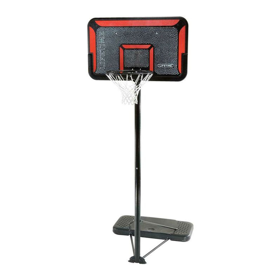
Summary of Contents for Lifetime 1258
- Page 1 MODEL N° 1258 OWNER’S MANUAL Keep this Product ID Number and use when contacting Customer Service:...
- Page 2 REGISTER YOUR PRODUCT ONLINE AT WWW.LIFETIME.COM At Lifetime, we are committed to providing innovative and quality products. While registering, you will have the opportunity to give us your feedback. Your input is valuable to us. Lifetime’s Promise to You: Maintaining your privacy is our long-standing policy at Lifetime. And you can rest assured that REGISTER today! Save this owner’s manual for future reference and in the event that...
- Page 3 SAFETY INSTRUCTIONS materials for parts and/or additional instruction material. Before beginning assembly, Proper and complete assembly, use and supervision sections to separate during play or transport. Most injuries are caused by misuse and/or not following instructions. Use caution when using this product. BEFORE BEGINNING ASSEMBLY are missing, call our Customer Service Department.
- Page 4 TOOLS AND PARTS REQUIRED FOR THIS ASSEMBLY Adjustable Wrench Phillips Screwdriver Rubber Mallet Sand Scrap Wood (150 lb) Water Hose *Two adults required to complete assembly* Only adults should set up the product. Do not allow children in the setup area until assembly is complete.
- Page 5 ASSEMBLY GUIDES Refer to the following areas throughout the instructions to assist in the assembly process: This area is located at the top, TOOLS AND HARDWARE REQUIRED FOR THIS PAGE left-hand corner of the page and indicates which tools and hardware are needed to complete the assembly steps on a page.
- Page 6 PARTS LIST Item Description Top Pole Middle Pole Bottom Pole Pole Plug Base Upper Pole Brace Right Bottom Pole Brace Left Bottom Pole Brace Cross Tube Right Foot Left Foot Wheel Cross Tube Cap (May come applied to Cross Tube)
- Page 7 HARDWARE LIST Item Description Streamline Hardware AOR 1/2” Washer Base Plug AOM 5/16” Cap Nut ABD 5/16” Washer AOQ 3/8” Allen Wrench CCL 3/16” Allen Wrench...
-
Page 8: Ali Upper Pole Brace
PARTS IDENTIFIER Parts shown at 10% of Actual Size 43” *Do not remove Top Pole from Middle Pole until instructed Top Pole Warning Sticker 43” Middle Pole 43” Bottom Pole 41” Upper Pole Brace Right Bottom Pole Brace Left Bottom Pole Brace Cross Tube... -
Page 9: Amu Wheel
PARTS IDENTIFIER Parts shown at 10% of Actual Size Parts shown at 5% of Actual Size Base Parts shown at 25%Actual Size Left Foot Right Foot Pole Plug Wheel Part shown at Actual Size Cross Tube Cap (may come applied to Cross Tube) -
Page 10: Aor 1/2" Washer
HARDWARE IDENTIFIER STREAMLINE HARDWARE Hardware shown at Actual Size 5/16” Flange (Not actual length) Jam Nut Base Plug (Not actual length) 1/2” Washer... -
Page 11: Aom 5/16" Cap Nut
HARDWARE IDENTIFIER STREAMLINE HARDWARE (CONTINUED) Hardware shown at Actual Size 5/16” Washer 5/16” Cap Nut Cap Nut 3/16” Allen Wrench Washer 3/8” Allen Wrench... - Page 12 POLE ASSEMBLY HARDWARE REQUIRED Hardware shown at Actual Size Domed Counter- 5/16” Cap Nut PARTS REQUIRED Parts shown at 10% of Actual Size 43” *Do not remove Top Pole from Middle Pole until instructed Top Pole Warning Sticker 43” Middle Pole 43”...
- Page 13 TOOLS AND HARDWARE REQUIRED FOR THIS PAGE While the Top Pole (ALH) is still inside the , pull the plastic off the Top Pole. It may be necessary to loosen the Poles before pulling out the plastic. Warning Sticker...
- Page 14 TOOLS AND HARDWARE REQUIRED FOR THIS PAGE Slide the Top Pole (ALH) far enough out of the so that it does not obstruct the holes at the bottom of the Middle Pole. Then Do not overtighten the Cap Nut. If the end of...
- Page 15 TOOLS AND HARDWARE REQUIRED FOR THIS PAGE Position the Top Pole (ALH) Adjustment to the Top Pole and...
- Page 16 TOOLS AND HARDWARE REQUIRED FOR THIS PAGE Align the hole in the Bottom Pole (ALE) and slide the Middle Pole over the Bottom Pole. Insert a through the small hole in the Middle Pole into the slot in the Bottom Pole Note: The 1/4”...
- Page 17 TOOLS AND HARDWARE REQUIRED FOR THIS PAGE ATTENTION: THIS STEP CANNOT BE REVERSED! Bottom Pole (ALE) very must be done even if the covers the slot on the Bottom Pole before seating has occurred. If the Middle Pole does not completely cover the slot on the Bottom Pole after seating has occurred, DO NOT COMPLETE ASSEMBLY.
-
Page 18: Abd 5/16" Washer
RIM & BACKBOARD TO POLE ASSEMBLY HARDWARE REQUIRED Hardware shown at Actual Size 5/16” Flange 5/16” Washer... - Page 19 RIM & BACKBOARD TO POLE ASSEMBLY PARTS REQUIRED Parts shown at 10% of Actual Size Part shown at 5% of Actual Size TOOLS REQUIRED Adjustable Wrench...
- Page 20 TOOLS AND HARDWARE REQUIRED FOR THIS PAGE Insert the Rim (ALX) into the slots on the front of the Rim Brackets Rim Braces Note: The Rim Braces will fi t within the notches of the Backboard as shown.
- Page 21 TOOLS AND HARDWARE REQUIRED FOR THIS PAGE HAVE ONE ADULT HOLD THE BACKBOARD AND RIM ASSEMBLY UNTIL THIS SECTION HAS BEEN COMPLETED Place the Top Pole (ALH) Rim Brackets...
- Page 22 TOOLS AND HARDWARE REQUIRED FOR THIS PAGE Insert the through the Rim (ALX) in the hole indicated, and insert the Bolt into the upper hole on the and into the Top Pole (ALH). Also insert the...
- Page 23 TOOLS AND HARDWARE REQUIRED FOR THIS PAGE Attach the Rim (ALX) to the and Top Pole (ALH) by securing a onto the . Also secure a (APN) onto the...
- Page 24 TOOLS AND HARDWARE REQUIRED FOR THIS PAGE Top Pole (ALH)
- Page 25 TOOLS AND HARDWARE REQUIRED FOR THIS PAGE Insert a...
- Page 26 TOOLS AND HARDWARE REQUIRED FOR THIS PAGE Slide a over the , and Note: Repeat steps 2.6 and 2.7 to attach the other Backboard Brace to the Backboard and Rim Brackets. Note: Lay the assembly on the ground with the Rim (ALX) facing upward and the Backboard tilted on its side.
- Page 27 POLE TO BASE ASSEMBLY HARDWARE REQUIRED Hardware shown at Actual Size (Not actual length) 1/2” Washer Cap Nut (Not actual length) 5/16” Washer 3/8” Allen Wrench Jam Nut 3/16” Allen Wrench...
- Page 28 POLE TO BASE ASSEMBLY PARTS REQUIRED Parts shown at 10% of Actual Size 41” Upper Pole Brace Right Bottom Pole Brace Left Bottom Pole Brace Cross Tube Parts shown at 25% of Actual Size Left Foot Right Foot Pole Plug Wheel Part shown at 5% of Actual Size Part shown at Actual Size...
- Page 29 TOOLS AND HARDWARE REQUIRED FOR THIS PAGE Attach the Cross Tube (BDB) to the ALK) WARNING Do not overtighten the Cap Nut. If necessary, insert the into the ends of the Cross Tube (BDB) Note: Cross Tube Caps may come preassembled to the Cross Tube.
- Page 30 TOOLS AND HARDWARE REQUIRED FOR THIS PAGE of the Attach the Upper Pole Braces (ALI) to the and the Bottom Pole Underside View of Base...
- Page 31 TOOLS AND HARDWARE REQUIRED FOR THIS PAGE (Not actual length) (Not actual size) CAUTION: HAVE ONE ADULT HOLD THE POLE UNTIL THE Insert the into the Bottom Pole (ALE) in the orientation Left and Right and the...
- Page 32 TOOLS AND HARDWARE REQUIRED FOR THIS PAGE Attach the Upper Pole Braces (ALI) to the Bottom Pole (ALE)
- Page 33 TOOLS AND HARDWARE REQUIRED FOR THIS PAGE (Not actual length) Insert the into each Wheel (AMU) . Then step on the Base to snap them in place.
- Page 34 HARDWARE REQUIRED Hardware shown at Actual Size Base Plug PARTS REQUIRED Part shown at 10% of Actual Size TOOLS REQUIRED Sand (150 lb) Water Hose...
- Page 35 TOOLS AND HARDWARE REQUIRED FOR THIS PAGE (150 lb) Two adults are required to complete assembly. To prevent serious injuries, the Pole should be held down by one adult at all times while the Base is being fi lled. (150 lb of sand required) a.
- Page 36 TOOLS AND HARDWARE REQUIRED FOR THIS PAGE Two adults are required to complete assembly. To prevent serious injuries, the Pole should be held down by one adult at all times while the Base is being fi lled. a. Insert a Base Plug (AZY) into the in the hole closest to the Pole.
- Page 37 TOOLS AND HARDWARE REQUIRED FOR THIS PAGE Attach Net (AKZ) to the Rim (ALX). Note: If a replacement Net is needed, please call our Customer Service Department. Our Nets are shorter than average to reduce the risk of entanglement.
- Page 38 OPERATION OF HEIGHT ADJUSTMENT SYSTEM TO RAISE OR LOWER THE HOOP: Bolt and Knob. playing position. MOVING THE SYSTEM The system must only be moved by people capable of b. Stand behind the system and pull on the Pole until the unit is balanced on its Wheels.
- Page 39 POLE CARE AND SYSTEM MAINTENANCE Department for replacement parts. Use an emery cloth to completely remove any rust or chipped paint.
- Page 40 NOTES...
- Page 41 NOTES...
- Page 42 ® ENHANCE YOUR LIFETIME PURCHASE BY ADDING ACCESSORIES OR OTHER GREAT PRODUCTS: To purchase accessories or other Lifetime Products, visit us at: www.lifetime.com Or call: 1-800-424-3865...
- Page 43 Nunca juegue con un equipo dañado. avant utilisation. del viento, lejos de propiedades personales que puedan dañarse www.lifetime.com #1007960 1/12/2006...
- Page 44 In addition, defects resulting from intentional damage, negligence, unreasonable use or this policy. 5. This product is not intended for institutional or commercial use; Lifetime Products, Inc. does not assume state to state. ALL WARRANTY CLAIMS MUST BE ACCOMPANIED BY A SALES RECEIPT.
Need help?
Do you have a question about the 1258 and is the answer not in the manual?
Questions and answers