Table of Contents
Advertisement
Quick Links
Download this manual
See also:
Instruction Manual
FM STEREO/AM TUNER
FM STEREO / AM TUNER AMPLIFIER
INPUT
ENERGY SAVE
CD
MD
CDR/PC
LINE/DVD
ACOUSTIC
PRESENCE
FM
AM
TAPE
OFF / 1 / 2 / 3
STANDBY / ON
WIDE RANGE AMPLIFIER
TECHNOLOGY
PHONES
MEMORY
FM MODE
CLEAR
Asian model
SAFETY-RELATED COMPONENT WARNING!!
COMPONENTS IDENTIFIED BY MARK
SCHEMATIC DIAGRAM AND IN THE PARTS LIST
ARE CRITICAL FOR RISK OF FIRE AND ELEC-
TRIC SHOCK. REPLACE THESE COMPONENTS
WITH ONKYO PARTS WHOSE PARTS NUMBERS
APPEAR AS SHOWN IN THIS MANUAL.
MAKE LEAKAGE-CURRENT OR RESISTANCE
MEASUREMENTS TO DETERMINE THAT EXPO-
SED PARTS ARE ACCEPTABLY INSULATED FORM
THE SUPPLY CIRCUIT BEFORE RETURNING THE
APPLIANCE TO THE CUSTOMER.
SERVICE MANUAL
AMPLIFIER
MODEL R-805TX
VOLUME
ENERGY SAVE
STANDBY / ON
DISPLAY
PRESET
PHONES
TUNING
R-805TX
Silver model
SUPP, SUPT
230-240V AC, 50Hz
SUDT
120 V AC, 60 Hz
FM STEREO / AM TUNER AMPLIFIER
INPUT
CD
MD
CDR
LINE/DVD
ACOUSTIC
PRESENCE
FM
AM
TAPE
OFF / 1 / 2 / 3
MEMORY
FM MODE
CLEAR
WIDE RANGE AMPLIFIER
ACCUCLOCK
TECHNOLOGY
European model
ON THE
R-805TX
Ref. No. 3681
052001
VOLUME
DISPLAY
PRESET
TUNING
R-805TX
Advertisement
Table of Contents

Related Manuals for Onkyo R-805TX


Summary of Contents for Onkyo R-805TX
-
Page 1: Service Manual
SCHEMATIC DIAGRAM AND IN THE PARTS LIST ARE CRITICAL FOR RISK OF FIRE AND ELEC- TRIC SHOCK. REPLACE THESE COMPONENTS WITH ONKYO PARTS WHOSE PARTS NUMBERS APPEAR AS SHOWN IN THIS MANUAL. MAKE LEAKAGE-CURRENT OR RESISTANCE MEASUREMENTS TO DETERMINE THAT EXPO-... -
Page 2: Specifications
R-805TX SPECIFICATIONS Amplier Section 50 dB Quieting sensitivity FM: Mono 17.2 dBf, 2.0 µV (75 ohms) Power output Stereo 37.2 dBf, 20.0 µV (75 ohms) 20 watts per channel, min RMS, at 4 ohms, both channels driven 1 kHz, Captur e ratio with no mor e than 0.6% THD... -
Page 3: Service Procedures
R-805TX SERVICE PROCEDURES 5. Changing the AM band step 1. Replacing the fuses The tuning step selector switch is not provided in this model. When you change the band step, change the parts as shown This symbol located near the fuses indicates that the below. -
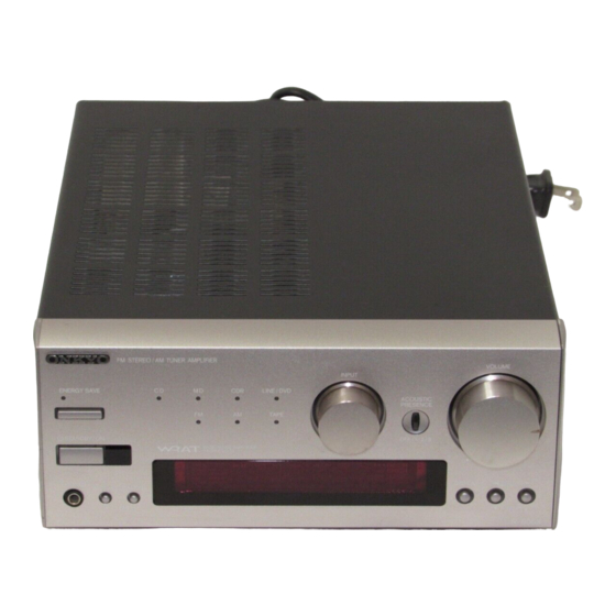
Page 4: Panel Views
INPUT selector OUTPUT OUTPUT ENERGY SA VE indicator ENERGY SA VE button ACOUSTIC PRESENCE button VOLUME control Remote control sensor TAPE This unit (R-805TX) TAPE ANTENNA For the Asian model: FM STEREO / AM TUNER AMPLIFIER VOLUME CAUTION: SPEAKER INPUT... -
Page 5: Remote Controller
R-805TX REMOTE CONTROLLER • Use the following buttons to control components that are connected to the - system. • You can control the other -connected components with the supplied remote controller. • The remote controller buttons operate in the same way as the buttons on each component with the same indication. -
Page 6: Exploded View
R-805TX EXPLODED VIEW P901(P/PT) P901 P953 P851 P801 F902 F901 E901 Q527 Q525 Q526 Q528 T901 P966 P965... -
Page 7: Parts List
R-805TX PARTS LIST CAUTION: Replacement for transistor of mark *, if necessary must be made from the same bata group (H ) as the original type. REF.NO. PART NO. DESCRIPTION REF.NO. PART NO. DESCRIPTION P965 27150448A Shield plate 27111147A Front bracket... - Page 8 R-805TX IC BLOCK DIAGRAMS AND DESCRIPTIONS TC9184AP(ELECTRONIC TONE CONTROL) CK DATA STB LEVEL SHIFT BASS+ BASS+ BASS- BASS- TREBLE- TREBLE- TREBLE+ TREBLE+ Pin No. Symbol Function Power supply voltage terminals (Analog section) 2/15 BASS+ Volume terminal 3/14 BASS- 5/12 TREBLE-...
- Page 9 R-805TX TA7291S(VOLUME MOTOR DRIVER) Vref INPUT OUTPUT MODE OUT1 OUT2 STOP CW/CCW CCW/CW BRAKE REGU- OUT1 LATOR CCW: Counter-clockwise direction CW: Clockwise direction OUT2 PROTECTOR 10-BT-167GK(FL TUBE) TIMER TRACK AUTO MONO STEREO W.DAY MUTING W.END MEMORY S.BASS REPEAT DIRECT SLEEP RANDOM :This model is not used.
-
Page 10: Microprocessor-Connection Diagram
R-805TX MICROPROCESSOR-CONNECTION DIAGRAM POWERSTOPPAGE DETECTOR Q781 RDS DECODER BU1923 TERMINAL POWER Q705 AMP. SW BUFFER Q704 CIRCUIT REMOTE SENSOR S709 INPUT SW Q405 VOLUME MOTOR DRIVER TA7291S Q703 TAPE FL TUBE X701 Vload X'TAL MEMORY DISPLAY P-UP AREA INITIALIZING SIGNAL... -
Page 11: Microprocessor-Terminal Description
R-805TX MICROPROCESSOR-TERMINAL DESCRIPTION Pin No. Function Description Pin No. Function Description 4G~10G Grid output pins for FL tube. CD indicator output pin Positive power supply pin MD indicator output pin POWER1 Power supply control pin for AC outlet and FL tube. -
Page 12: Wiring View
R-805TX WIRING VIEW NAETC- 6802 TUNER PACK P301B P302B P903 NAPS- 6805 NAPS- 6803 P952A JL901A P952B P301A P302A JL953 P951A JL703B P951B JL901B TP701 P902 JL903A JL903B JL702B P403B P403A JL902B JL902A P501 NAAF- 6805 JL701B P402B P402A JL502B... -
Page 13: Printed Circuit Board-Parts List
R-805TX PRINTED CIRCUIT BOARD-PARTS LIST MAIN CIRCUIT PC BOARD (NAAF-6801-2C/2D/2E) CIRCUIT NO. PART NO. DESCRIPTION CIRCUIT NO. PART NO. DESCRIPTION Capacitors C925 393352227 2200 u F,25V, Elect. Q301 22240881 TC9273N-010 C929 393361017 100 u F,35V, Elect. Q405 22240239 TA7291S C930 393341007 10 u F,16V, Elect. - Page 14 R-805TX CIRCUIT NO. PART NO. DESCRIPTION CIRCUIT NO. PART NO. DESCRIPTION Capacitors Transistors C951,C962 354780339 3.3 u F,50V, Elect. Q415-Q422 2211945 2SK246-GR C952 393384797 0.47 u F,50V, Elect. Q423-Q426 2213631 or RN1241-A or C965 393361017 100 u F,35V, Elect. 2213632...
- Page 15 R-805TX SCHEMATIC DIAGRAM MOTHER BOARD P303 TO NAAF-6805 TO NAAF-6805 C301 P401A 101K R301 R303 LEFT P403A Q521 Q301 TC9273N-010 23.1V R517 VDD 28 R304 Q525 R302 R515 0.55V RIGHT R509 R565 R507 C302 (1/2W) 2SC2235 MD-PLAY 101K (1/2W) 27.9V 22.9V...
- Page 16 R-805TX SCHEMATIC DIAGRAM DISPLAY/TONE SECTIONS(European model only) NADG-6804 FCE/VCE R748 R747 R746 R745 DATA PLLCE X701 D705 TUMUT R721 R719 XTL-4.19M C707 R718 STEREO TP701 NTC-45P27 2.7K R751 C781 R720 C706 R752 R750 R749 POWER1 CH220J CH220J VOLDOWN R715 C782...
- Page 17 223Z R706 MPD78044FGF-192-3BQ FCE/VCE 100/6.3 POWER2 C711 223Z VDD3 FCE/VCE 13 2.2/50 R729 R726 10K R705 SBASS3 100/6.3 POFF OR MPD78P048(R-805TX) D702 ROTB SBASS3 12 R727 10K R704 TAPE SBASS2 D713 ROTA SBASS2 11 C701 R728 R703 POWER2 SBASS1 C702 +5.6V...
-
Page 18: Packing View
Sales & Product Planning Div. : 2-1, Nisshin-cho, Neyagawa-shi, OSAKA 572-8540, JAPAN Tel: 072-831-8111 Fax: 072-833-5222 ONKYO U.S.A. CORPORATION 18 Park Way, Upper Saddle River, N.J. 07458, U.S.A. Tel: 201-785-2600 Fax: 201-785-2650 E-mail: onkyo@onkyousa.com ONKYO EUROPE ELECTRONICS GmbH Industriestrasse 20, 82110 Germering, GERMANY Tel: 089-849-320 Fax: 089-849-3265 E-mail: info@onkyo.de... -
Page 19: Packing Procedures
R-805TX PACKING PROCEDURES 1. Pad A outside Proceed the operation of step 1 to 6. : inside Top view outside Bottom view : outside Turn up 2. Pad B Proceed the operation of step 1 to 6. : inside Insert the pad A to pad B.
Need help?
Do you have a question about the R-805TX and is the answer not in the manual?
Questions and answers