Table of Contents
Advertisement
Quick Links
Advertisement
Table of Contents

Related Manuals for Sensidyne SensAlarm Plus


Summary of Contents for Sensidyne SensAlarm Plus
- Page 1 Universal Gas Monitoring System User Manual Document No. 360-0126-01 (Revision D) Sensidyne, LP 1000 112 Circle N, Suite 100 St. Petersburg, Florida 33716 USA 800-451-9444 • +1 727-530-3602 • +1 727-539-0550 [fax] web: www.sensidyne.com • e-mail: info@sensidyne.com...
-
Page 2: How To Use This Manual
Section 3, Operating Functions and Section 4, Alarms and Relays. The SensAlarm Plus Gas Monitor is menu driven, so is important to become familiar with how the four magnetic switch controls are used to navigate through the menus, select specific menu items, and change the many different parameters available to the user. -
Page 3: Table Of Contents
User Manual SensAlarm Plus – Universal Gas Monitoring System Table of Contents How to Use This Manual..........................2 Basic Menu Controls Guide ..........................2 Packing List and Notices..........................7 WARNINGS ..............................8 INTRODUCTION ......................10 Product Versions ..........................10 Standard Features..........................11 1.2.1 Universal Sensor Capability......................11 1.2.2 Large Displays for Ease of Operation..................11... - Page 4 SensAlarm Plus – Universal Gas Monitoring System User Manual Fire or other Code Compliance Issues and annunciation requirements..........22 Monitor Installation ..........................22 2.3.1 AC Power............................ 24 2.3.2 DC Power ........................... 25 2.3.3 Wiring Procedure (4-20 mA Output)................... 25 2.3.4 Wiring Procedure (Relay Outputs) .....................
- Page 5 User Manual SensAlarm Plus – Universal Gas Monitoring System Red Strobe - Relay7, Amber Strobe-Relay8 ..................58 4.6.1 Latching or Non-Latching......................58 4.6.2 Norm Energized/ Norm De-Energized ..................59 4.6.3 Time Delay..........................59 MENU STRUCTURE & MAP..................60 Basic Guide to Using the Menu System .......................60 PLUS Menu Structure ........................60...
- Page 6 SensAlarm Plus – Universal Gas Monitoring System User Manual APPENDIX B: SPECIFICATIONS................108 APPENDIX C: TROUBLESHOOTING GUIDE ............109 10 APPENDIX D: TUV CERTIFICATION............... 111 11 APPENDIX F: RETURNED MATERIAL AUTHORIZATION ........112 12 APPENDIX G: CONFIGURATION REFERENCE ............. 113 13 APPENDIX H: MOUNTING DRAWINGS ..............
-
Page 7: Packing List And Notices
Sensidyne, LP are protected through use and registration in the United States of America. SOFTWARE LICENSE The software included with the SensAlarm Plus Gas Monitor is the property of Sensidyne, LP and shall remain the property of Sensidyne, LP in perpetuity. The software is protected by U.S. and international copyright laws and is licensed for specific use with the SensAlarm Plus Universal Gas Monitoring System. -
Page 8: Warnings
DO NOT attempt to repair or modify instrument, except as specified in the Operation & Service Manual. If repair is needed, contact the Sensidyne Service Dept. to arrange for a Returned Material Authorization (RMA) (See Section 0 for details). - Page 9 SENSIDYNE® service technician, could cause the product to fail to perform as designed and persons who rely on this product for their safety could sustain severe personal injury or death.
-
Page 10: Introduction
1 Introduction This manual provides specific information concerning the installation, operation, calibration, and maintenance of the SensAlarm Plus Universal Gas Monitoring System. SensAlarm Plus is capable of detecting the presence of potentially hazardous concentrations of Combustible vapors and gases, Toxic gases and Oxygen deficiency. -
Page 11: Standard Features
1.2.4 Transportable Calibration SensAlert Plus sensors have transportable calibration capabilities. Sensors may be calibrated in the shop or at Sensidyne and then installed in the field without any special tools or adjustments. When a new sensor is installed in the unit, the Monitor automatically adjusts to recognize the new gas type and range and adjusts system function accordingly. -
Page 12: Factory Installed Options
The sensor is mounted in a sensor interface assembly on the bottom of SensAlarm Plus. It can, however, be located up to 100 feet away. In this manner, the detection of heavier or lighter than air gases and the use of special fixtures such as sample draw or duct mounting can be easily done. -
Page 13: Sensalarm Plus Components
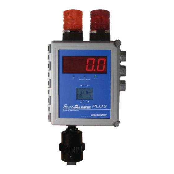
User Manual SensAlarm Plus – Universal Gas Monitoring System Plus 1.4 SensAlarm Components 1.4.1 Sensor Interface Assembly The sensor interface assembly contains the electronics that operate the sensor and houses the SensAlert Plus sensor and the optional Test-on- Demand™ cell. - Page 14 SensAlarm Plus – Universal Gas Monitoring System User Manual Single or Dual Strobes (Red or Amber and Red) Large Format LED Display Power Source Available LEDs External Battery << Magnetic Controls (OK LCD Display Magnetic Controls ( Reset Switch And Sounder...
-
Page 15: Liquid Crystal Display And Magnetic Controls
User Manual SensAlarm Plus – Universal Gas Monitoring System 1.4.7 Liquid Crystal Display and Magnetic Controls The Liquid Crystal display is backlit and has a contrast adjustment. Gas Concentration or Value The gas concentration is displayed in large characters with the units of measure (ppm, %vol, %LEL), as required by the installed sensor. -
Page 16: Sensor Types
User Manual 1.4.8 Sensor Types NOTE DO NOT attempt to install any other sensor type into a SensAlarm Plus except those manufactured by Sensidyne and intended for this product. A complete list of available sensors, sensor specifications, interferences, and calibration equipment can be found on line at www.sensidyne.com. -
Page 17: Sensalarm Plus Housing
(classified) safe area just prior to installation of the sensor into the SensAlarm Plus Monitor. The sensor can be unplugged from the battery board for a maximum of 5 minutes. Note that, if unplugged or unpowered for 15 seconds, a sensor may take 2 minutes to return to zero once it is plugged into a Monitor or powered up. -
Page 18: Amber Strobe (Option)
1.4.12 Amber Strobe (option) A second strobe is optional for SensAlarm PLUS. When this is ordered, An Amber strobe is placed on the left and the Red strobe is on the right. The Amber strobe will flash on low alarm and high alarm. The red strobe flashes only on high alarm. -
Page 19: Electronics Modules
95 dB Sounder Reset Switch The SensAlarm Plus Monitor has non-intrusive controls that do not require the enclosure to be opened for calibration, alarm adjustment, or other functions. However, test points are provided on the main PCA in case service personnel wish to monitor the output. -
Page 20: Display Pca
The front and rear views of the Display LCD PCA are shown below about half of actual size on the printed page. The Display PCA back is barely visible inside the front cover of SensAlarm Plus. The display contrast adjustment can be reached with a finger. -
Page 21: Barrier Pca
User Manual SensAlarm Plus – Universal Gas Monitoring System 1.5.4 Barrier PCA The barrier PCA is an intrinsic safety barrier for the sensor interface and is located in the lower left corner of the enclosure. This circuitry is not yet approved by a third party for sensor location in a hazardous (classified) area. -
Page 22: Installation
30 or 60 minutes. This provides for operation during a power failure, and enough time to furnish valuable status information to emergency responders. SensAlarm PLUS is available with battery back-up to provide 60 minutes of non-alarm operation and at least 30 minutes of operation under full alarm conditions 2.3 Monitor Installation... - Page 23 User Manual SensAlarm Plus – Universal Gas Monitoring System Refer to Section 13 Appendix H Document No. 360-0126-01 (Rev. D) Page 23...
-
Page 24: Ac Power
SensAlarm Plus – Universal Gas Monitoring System User Manual Wiring Power On-Off Switch (AC & External DC) Alarm Relays (4) Strobe Main PCA Door Ribbon Cable AC Power In TB1 Strobe AC Fuses DC Power In TB2 Beeper Optional DC Fuses... -
Page 25: Dc Power
1) Refer to photograph. 2) Verify that the conduit and the Monitor are properly connected. 3) Unlatch and open the SensAlarm Plus cover. 5) Verify that the total resistance of the wiring does not exceed the allowable loop resistance. 6) Thread the wires through the bottom Rigid / IMC grounding hub. (A cable that totally encases these wires is recommended.) Make certain you tighten the Rigid / IMC grounding hub... -
Page 26: Start Up
1) Unscrew the retainer ring (turn left to right) and remove the sensor holder by pulling downward. 2) Open the SensAlarm Plus enclosure by releasing the two corner latches. Locate and turn on the power switch and then close the cover. -
Page 27: Operating Functions
For further information, please refer to Recommended Practice for the Installation, Operation, and Maintenance of Combustible Gas Detection Instruments (ANSI/ISA TR12.13.02-2003) published by the ISA. For a list of calibration equipment available for calibrating the SensAlarm Plus Monitor see Section 6.5: Calibration Equipment. Always: Allow the Monitor to stabilize with power applied for at least 1 hour before performing any calibration. -
Page 28: Zeroing The Monitor
SensAlarm Plus – Universal Gas Monitoring System User Manual The Calibration Mode screen displays the calibration gas level, date, and time Calibration Mode > Calibration Mode of the last successful span calibration. Last Cal @ 50 PPM Maintenance Mode 05/17/06... -
Page 29: Span Calibration
FAIL Data Review If Zero fails after second attempt, replace Sensor and repeat Zero. Test-on-Demand If still unable to set Zero, contact the Sensidyne Service Department. System Config Select OK To Continue 3.1.2 Span Calibration Important information concerning sensor function is stored in sensor memory each time it is calibrated and during normal operation. - Page 30 Cyanide, Nitrogen Dioxide, Phosgene, Sulfur Dioxide, and Ethylene Oxide. (Refer to Sensor Data Sheet) Calibration Gas is available from Sensidyne. Use of non-Sensidyne calibration gas is AT YOUR OWN RISK. Note: During calibration, the 4–20 mA signal (using factory settings) is locked at 4 mA for many sensors and 17.38 mA (20.9% Vol) for ambient Oxygen sensors.
- Page 31 User Manual SensAlarm Plus – Universal Gas Monitoring System This screen displays the current calibration gas concentration. 3) Use the arrows to adjust the calibration gas level to match the Set Cal Gas Conc > Calibration Mode concentration of the calibration gas.
- Page 32 SensAlarm Plus – Universal Gas Monitoring System User Manual Cal In Progress > Calibration Mode 6) During calibration this screen will appear. Exposure times will vary Cal To: 50 PPM Maintenance Mode depending on the gas. Data Review Level: 19 PPM Test-on-Demand The gas “Level”...
-
Page 33: Sensor Adjustment
User Manual SensAlarm Plus – Universal Gas Monitoring System 3.2 Sensor Adjustment This section covers Sensor Adjustment for either a Catalytic Bead or Infrared Combustible sensor. There are no adjustments possible for an Oxygen or Toxic sensor. There are three settings in Sensor Adjustment: Calibration Gas Selection from a preset list. -
Page 34: Select Calibration Gas
SensAlarm Plus – Universal Gas Monitoring System User Manual This screen will appear if an Oxygen or Toxic gas sensor is installed. No Sensor Adjustment > Calibration Mode further adjustments are available through this control. No Adjustments Maintenance Mode Data Review... -
Page 35: Selecting A K-Factor
User Manual SensAlarm Plus – Universal Gas Monitoring System This screen appears if an Infrared Combustible sensor is installed. Note: The IR Combustible sensor must be recalibrated if the calibration gas that is selected is different from the current calibration gas. The IR Combustible... - Page 36 SensAlarm Plus – Universal Gas Monitoring System User Manual This screen appears and shows that Methane is the selected Calibration Gas. Also, it has a list of preset K-Factors along with “None” and “Custom K Factor” Select K Factor Using the << anytime will exit the current routine and restore the initial setting.
-
Page 37: Selecting A Custom K-Factor
K-Factors. Additional K-Factors for Catalytic Bead and Infrared Combustible sensors can be found in their respective Sensor Data sheets. Please consult Sensidyne Customer Service if a K-Factor is not on the Sensor Data sheet. Note: A custom K-factor is not available for Infrared Combustible sensors if the Calibration gas is Methane. -
Page 38: Tod Mode Adjustment
SensAlarm Plus – Universal Gas Monitoring System User Manual This screen appears displaying a Custom K-Factor when the Calibration gas is Propane. Select K Factor 8) Use the arrows to adjust the value to 1.18. > Calibration Mode Cal Gas Is Propane... -
Page 39: Auto Mode, Enable/Disable
User Manual SensAlarm Plus – Universal Gas Monitoring System System Configuration > Calibration Mode 4) Use the arrows to move the cursor to “ToD Mode Adjustment.” --more-- Maintenance Mode > ToD Mode Adjustment Sensor Adjustment Data Review Set Password Test-on-Demand... -
Page 40: Tod Auto Mode, Test Date/Time
SensAlarm Plus – Universal Gas Monitoring System User Manual 3.3.2 ToD Auto Mode, Test Date/Time Note: Auto mode (see 3.3.1) must be enabled before this start time for tests to occur at the date and time set in this routine. If auto enable is set after the start time has occurred, the start time will be changed to the date/time of day the auto test was enabled and will repeat at the interval set in the Days Between Tests routine. -
Page 41: Tod Mode Adjustment, Cell Intensity
User Manual SensAlarm Plus – Universal Gas Monitoring System This screen appears showing the current setting for number of days between tests. Adjust Num Of Days > Calibration Mode Maintenance Mode 4) Use the arrows to change number of days between tests. -
Page 42: Tod Mode Adjustment, Output Indicators
SensAlarm Plus – Universal Gas Monitoring System User Manual 3.3.5 ToD Mode Adjustment, Output Indicators There are “Output Indicators” that allow the Automatic Mode Test-On-Demand Activity to be monitored. Auto Mode must be enabled for this to function. To change the Output Indicators: ToD Mode Adjustment 1) Access the ToD Mode Adjustment Menu as shown in Section 3.3. -
Page 43: Alarms, Faults And Relays
User Manual SensAlarm Plus – Universal Gas Monitoring System 4 Alarms, Faults and Relays There are 4 Alarm levels that can be configured. See section 4.1 for detailed instructions. They are. Alarm 1- The lowest level alarm also referred to as “LO” Alarm Alarm 2- The middle level alarm also referred to as “HI”... -
Page 44: Alarms
SensAlarm Plus – Universal Gas Monitoring System User Manual 4.1 Alarms Alarms are indications of important detected levels of the target gas. This control is used to configure setting for each alarm. To configure an alarm: Main Menu > Calibration Mode Calibration Mode 1) Select OK to bring up the main menu. -
Page 45: Add A Relay
User Manual SensAlarm Plus – Universal Gas Monitoring System Alarm Configuration Screen This screen represents the current configuration settings for each of the alarms. The First line indicates which alarm is being set. Alarm 1 > Calibration Mode Relays Assigned The second line indicates which relays are assigned to the Alarm. -
Page 46: Delete A Relay
SensAlarm Plus – Universal Gas Monitoring System User Manual 4.1.2 Delete a Relay 1) Use the arrows to move the cursor to “Delete Relay”. 2) Select OK. Alarm 1 > Calibration Mode Relays Assigned 23 Maintenance Mode Add Relay > Delete Relay... -
Page 47: Ascending Or Descending Alarm Threshold
User Manual SensAlarm Plus – Universal Gas Monitoring System 3) To change and save the state to the displayed setting, Select OK. Alarm 1 > Calibration Mode Using the << anytime will exit the current routine and restore the initial setting. -
Page 48: Release Offset
SensAlarm Plus – Universal Gas Monitoring System User Manual This screen displays the current set point in units detected. Alarm 1 > Calibration Mode 3) Use the arrows to change the value of the alarm set point in units Setpoint Maintenance Mode detected. -
Page 49: Fault Functions
7) Select OK to save the new setting. 4.2 Fault Functions The SensAlarm PLUS control system is constantly assessing the internal operation of the monitor. Several critical functions are monitored constantly and can be assigned an indicator to announce the occurrence of a system fault. -
Page 50: Add A Relay
SensAlarm Plus – Universal Gas Monitoring System User Manual 6. Calibration Mode- Settings for output indications during calibration. Assigned Relays will transition during Calibration when enabled. Not assigned to any relays at the factory. 7. Maintenance Mode- Settings for output indications during Fault Functions >... -
Page 51: Enable Or Disable A Fault
User Manual SensAlarm Plus – Universal Gas Monitoring System Horn – Relay 6 Red Strobe – Relay 7 Amber Strobe – Relay 8 4.2.3 Enable or Disable a Fault Refer to section 4.1.3 for enabling or disabling a fault. The current state is shown on the Fault Configuration screen. -
Page 52: Warn Current-Relay5
SensAlarm Plus – Universal Gas Monitoring System User Manual Sensor End of Life 3) This screen appears showing the present Current Delay Value for the > Calibration Mode displayed fault. Use the arrows to adjust the fault current in 1... -
Page 53: Warn Current - Relay 5, Enable Or Disable
User Manual SensAlarm Plus – Universal Gas Monitoring System 4.3.2 Warn Current – Relay 5, Enable or Disable To Enable or Disable the Warning Current: 1) Access the Warn Current – Relay 5 Menu. Warn Current-Relay5 > Calibration Mode The following screen will be displayed. Notice that the cursor is indicating... -
Page 54: Relay 1-Fail, Relay 2, Relay 3, Relay 4
SensAlarm Plus – Universal Gas Monitoring System User Manual 4.4 Relay 1-Fail, Relay 2, Relay 3, Relay 4 The following settings apply to all four of the mechanical Relays: Latching/Non-latching Energized/De-Energized Time Delay Relay 1 - Fail is set at the factory to be non-latching, normally energized with a time delay of 10 seconds. -
Page 55: Time Delay
User Manual SensAlarm Plus – Universal Gas Monitoring System Monitor. All other Relays are factory set to be Normally De-Energized and they do not change state when power is removed from the monitor. This screen shows that Relay 1 is currently Normally Energized. -
Page 56: Horn - Relay 6
SensAlarm Plus – Universal Gas Monitoring System User Manual 4.5 Horn – Relay 6 The Internal Horn (or sounder) is located on the bottom of the enclosure. The sounder can be silenced with a red pushbutton switch. The alarm reset conforms to ISA alarm sequence 3A. -
Page 57: Time Delay
User Manual SensAlarm Plus – Universal Gas Monitoring System Note: Using the << anytime will exit the current routine and restore the initial setting. Horn – Relay 6 > Calibration Mode Maintenance Mode Timeout Enabled Data Review 3) This screen appears showing that the Horn timeout is enabled. -
Page 58: Red Strobe - Relay7, Amber Strobe-Relay8
SensAlarm Plus – Universal Gas Monitoring System User Manual This screen shows the current setting. 4) Use the arrows to change the value of the time delay. Note: Using the << anytime will exit the current routine and restore the initial Horn –... -
Page 59: Norm Energized/ Norm De-Energized
User Manual SensAlarm Plus – Universal Gas Monitoring System 3) This screen appears showing that Relay 1 is now Latching. 4) Select OK to save the change. 4.6.2 Norm Energized/ Norm De-Energized This feature sets the strobe to be either Normally Energized (On) or Normally De-Energized (Off). -
Page 60: Menu Structure & Map
User Manual 5 Menu Structure & Map The setup and operation of the SensAlarm Plus is controlled by parameters and procedures that are accessed through the menu structure. The menu structure is entered from the Normal Operation Display by selecting OK. - Page 61 User Manual SensAlarm Plus – Universal Gas Monitoring System 5.1.3. Data Review 5.1.3.1 Calibration Info “Last Cal @ ## PPM(%VOL, %LEL)” DD/MM/YY (YY/MM/DD) HH:MM:SS PreCal Val ##PPM (%VOL, %LEL) 5.1.3.2 Sensor Status Gas Name $$$$$ ### TWA Conc ## PPM (%LEL) (%VOL)
- Page 62 SensAlarm Plus – Universal Gas Monitoring System User Manual 5.1.3.7 Rly Alm Fault Config -Relay 1 – Fail 5.1.3.7.1 Latching (Non-Latching) Norm Energized (Norm De-Energized) Time Delay ### Sec. -Relay 2 5.1.3.7.2 Latching (Non-Latching) Norm Energized (Norm De-Energized) Time Delay ### Sec.
- Page 63 User Manual SensAlarm Plus – Universal Gas Monitoring System -Alarm 2 5.1.3.7.10 Relays Assigned ######## Enabled (Disabled) Ascending (Descending) Set point ### PPM (%LEL) (%VOL) Release Offs (Offset)### PPM (%LEL) (%VOL) Alarm 3 5.1.3.7.11 Relays Assigned ######## Enabled (Disabled) Ascending (Descending)
- Page 64 SensAlarm Plus – Universal Gas Monitoring System User Manual -Calibration Mode 5.1.3.7.18 Relays Assigned ######## Enabled (Disabled) Fault Current #.## -Maintenance Mode 5.1.3.7.19 Relays Assigned ######## Enabled (Disabled) Fault Current #.## -TOD Fail 5.1.3.7.20 (Test on Demand) Relays Assigned ######## Enabled (Disabled) Fault Current #.##...
- Page 65 User Manual SensAlarm Plus – Universal Gas Monitoring System 5.1.4. Test On Demand 5.1.4.1 4-20 mA Not Active “In Progress” screen, then result 5.1.4.2 4-20 mA Active “In Progress” screen, then result 5.1.5. System Configuration 5.1.5.1 Self Test Turns on and off all pixels, lights all LEDs and activates all installed relays 5.1.5.2 Alarm Settings...
- Page 66 SensAlarm Plus – Universal Gas Monitoring System User Manual Setpoint 5.1.5.2.1.1.5 to change value, then select “OK” to save Release Offset 5.1.5.2.1.1.6 Select OK to Save, UP= Increase Down = Decrease Alarm 2 5.1.5.2.1.2 Use Up Down For Next Selection Select “OK”...
- Page 67 User Manual SensAlarm Plus – Universal Gas Monitoring System Release Offset 5.1.5.2.1.2.6 Select OK to Save, UP= Increase Down = Decrease Alarm 3 5.1.5.2.1.3 Use Up Down For Next Selection Select “OK” Add Relay 5.1.5.2.1.3.1 Use Up Down For Next Selection Select “OK” to Add Relay 1 –...
- Page 68 SensAlarm Plus – Universal Gas Monitoring System User Manual TWA Alarm 5.1.5.2.1.4 Use Up Down For Next Selection Select “OK” Add Relay 5.1.5.2.1.4.1 Use Up Down For Next Selection Select “OK” to Add Relay 1 – Fail 5.1.5.2.1.4.1.1 Relay 2 5.1.5.2.1.4.1.2...
- Page 69 User Manual SensAlarm Plus – Universal Gas Monitoring System Fault Functions 5.1.5.2.2 Use Up Down For Next Selection Select “OK” to Access Head Fail 5.1.5.2.2.1 Use Up Down For Next Selection Select “OK” Add Relay 5.1.5.2.2.1.1 Use Up Down For Next Selection Select “OK” to Add Relay 1 –...
- Page 70 SensAlarm Plus – Universal Gas Monitoring System User Manual Missing Sensor 5.1.5.2.2.2 Use Up Down For Next Selection Select “OK” Add Relay 5.1.5.2.2.2.1 Use Up Down For Next Selection Select “OK” to Add Relay 1 – Fail 5.1.5.2.2.2.1.1 Relay 2 5.1.5.2.2.2.1.2...
- Page 71 User Manual SensAlarm Plus – Universal Gas Monitoring System Delete Relay 5.1.5.2.2.3.2 Use Up Down For Next Selection Select “OK” to Add Relay 1 – Fail 5.1.5.2.2.3.2.1 Relay 2 5.1.5.2.2.3.2.2 Relay 3 5.1.5.2.2.3.2.3 Relay 4 5.1.5.2.2.3.2.4 Horn -Relay 6 5.1.5.2.2.3.2.5 Red Strobe -Relay 7 5.1.5.2.2.3.2.6...
- Page 72 SensAlarm Plus – Universal Gas Monitoring System User Manual Adj Fault Current 5.1.5.2.2.4.4 Select OK to Save, UP= Increase Down = Decrease Adj Current Delay 5.1.5.2.2.4.5 Select OK to Save, UP= Increase Down = Decrease Output Current Track 5.1.5.2.2.5 Use Up Down For Next Selection Select “OK”...
- Page 73 User Manual SensAlarm Plus – Universal Gas Monitoring System Calibration Mode 5.1.5.2.2.6 Use Up Down For Next Selection Select “OK” Add Relay 5.1.5.2.2.6.1 Use Up Down For Next Selection Select “OK” to Add Relay 1 – Fail 5.1.5.2.2.6.1.1 Relay 2 5.1.5.2.2.6.1.2...
- Page 74 SensAlarm Plus – Universal Gas Monitoring System User Manual Delete Relay 5.1.5.2.2.7.2 Use Up Down For Next Selection Select “OK” to Add Relay 1 – Fail 5.1.5.2.2.7.2.1 Relay 2 5.1.5.2.2.7.2.2 Relay 3 5.1.5.2.2.7.2.3 Relay 4 5.1.5.2.2.7.2.4 Horn -Relay 6 5.1.5.2.2.7.2.5 Red Strobe -Relay 7 5.1.5.2.2.7.2.6...
- Page 75 User Manual SensAlarm Plus – Universal Gas Monitoring System Adj Fault Current 5.1.5.2.2.8.4 Select OK to Save, UP= Increase Down = Decrease Adj Current Delay 5.1.5.2.2.8.5 Select OK to Save, UP= Increase Down = Decrease TOD End Of Life 5.1.5.2.2.9 Use Up Down For Next Selection Select “OK”...
- Page 76 SensAlarm Plus – Universal Gas Monitoring System User Manual Relay 1 – Fail 5.1.5.2.3 Use Up Down For Next Selection Latching Non- Latching 5.1.5.2.3.1 Select “OK” to change status Norm Energized Norm De-energized 5.1.5.2.3.2 Select “OK” to change status Time Delay 5.1.5.2.3.3...
- Page 77 User Manual SensAlarm Plus – Universal Gas Monitoring System Warn Current – Relay 5 5.1.5.2.7 Use Up Down For Next Selection Latching Non- Latching 5.1.5.2.7.1 Select “OK” to change status Enabled Disabled 5.1.5.2.7.2 Select “OK” to change status Low Current Time Adj 5.1.5.2.7.3...
- Page 78 SensAlarm Plus – Universal Gas Monitoring System User Manual Time Delay 5.1.5.2.10.3 UP= Increase Down = Decrease Select OK to Save, 5.1.5.3 4/20ma Adjustment to change selection 4 mA 5.1.5.3.1 Up = Increase Down Decrease Select OK to Complete Select << To Cancel 20 mA 5.1.5.3.2...
- Page 79 User Manual SensAlarm Plus – Universal Gas Monitoring System Year 5.1.5.4.2.3 to change value, then OK Hour 5.1.5.4.2.4 to change value, then OK Minute 5.1.5.4.2.5 to change value, then OK 5.1.5.5 Communications Setup to change value 4-20 mA communication 5.1.5.5.1 None 5.1.5.5.1.1...
- Page 80 SensAlarm Plus – Universal Gas Monitoring System User Manual Stop Bits 5.1.5.5.3.4 to change value 5.1.5.5.3.4.1 Select OK To Save 5.1.5.5.3.4.2 Select OK To Save Hart Comm (if Installed) 5.1.5.5.4 No user adjustments 5.1.5.6 TOD Mode Adjustment Auto Mode Enable 5.1.5.6.1...
- Page 81 User Manual SensAlarm Plus – Universal Gas Monitoring System Days Between Tests 5.1.5.6.3 ”Adj Num Of Days” to change value, then OK Cell Intensity 5.1.5.6.4 ”50% Is Nominal” “Cell Intensity” ###% Up = Increase Down Decrease to change value, then OK Output Indicators 5.1.5.6.5...
- Page 82 SensAlarm Plus – Universal Gas Monitoring System User Manual Select K Factor 5.1.5.7.2 If CB CMB Sensor is installed And Cal Gas Is Methane” to change selection None 5.1.5.7.2.1 None K Factor is: 1.00” Select OK To Save Select << to Cancel Hydrogen 5.1.5.7.2.2...
- Page 83 User Manual SensAlarm Plus – Universal Gas Monitoring System None 5.1.5.7.3.1 None K Factor is: 1.00” Select OK To Save Select << to Cancel Hydrogen 5.1.5.7.3.2 Hydrogen K Factor is: .65” Select OK To Save Select << to Cancel Methane 5.1.5.7.3.3...
- Page 84 SensAlarm Plus – Universal Gas Monitoring System User Manual Custom K Factor 5.1.5.7.4.2 “Custom K Factor K Factor is: 1.00” Select OK To Save Select << to Cancel Select K Factor 5.1.5.7.5 If IR CMB Sensor is installed And Cal Gas Is Methane”...
- Page 85 User Manual SensAlarm Plus – Universal Gas Monitoring System Hexane 5.1.5.7.6.5 Hexane K Factor is: 1.61” Select OK To Save Select << to Cancel Custom K Factor 5.1.5.7.6.6 Custom K Factor K Factor is: 1.07” to change value Select OK To Save Select <<...
- Page 86 SensAlarm Plus – Universal Gas Monitoring System User Manual 5.1.5.9 Reset Defaults “This will reset all Relays, Alarms, and Faults to Factory Default Values” Select OK To Continue (Selecting OK will restart the Monitor) Select << to Cancel 5.1.5.10 Set Transmitter Tag $$$$$$$$$$$$$$$$$$$$$ 5.1.5.10.1...
-
Page 87: Main Menu (Screens)
User Manual SensAlarm Plus – Universal Gas Monitoring System 5.2 Main Menu (screens) Main Menu As shown on the example display to the right, the top level > Calibration Mode > Calibration Mode (main) menu allows the selection of several submenus,... -
Page 88: Set Cal Gas Concentration
SensAlarm Plus – Universal Gas Monitoring System User Manual 5.2.1.3 Set Cal Gas Concentration Refer to Section 3.1.2 This menu item allows selecting the calibration gas concentration. The Set Cal Gas Conc keys can be used to adjust the concentration. The value will be stored >... -
Page 89: Calibration Info
User Manual SensAlarm Plus – Universal Gas Monitoring System 5.2.3.1 Calibration Info The Calibration Info review screen displays the last Calibration gas concentration, the Date of last successful calibration, and Pre Calibration gas concentration (as found condition). Calibration Info >... -
Page 90: Fault Currents
SensAlarm Plus – Universal Gas Monitoring System User Manual 5.2.3.5 Fault Currents The Fault Currents review screen displays the fault currents in mA for each of the nine Fault Functions. Fault Currents Fault Currents > Calibration Mode > Calibration Mode Head Fail 1.00... -
Page 91: Tod Review
User Manual SensAlarm Plus – Universal Gas Monitoring System 5.2.3.7.17 Out Cur Track 5.2.3.7.18 Calibration Mode 5.2.3.7.19 Maintenance Mode Rly Alm Fault Config > Calibration Mode 5.2.3.7.20 ToD Fail Sensor Fail Maintenance Mode Relays Assigned 1 5.2.3.7.21 ToD End of Life... -
Page 92: Test-On-Demand (Main Menu)
SensAlarm Plus – Universal Gas Monitoring System User Manual 5.2.4 Test-On-Demand (Main Menu) The Test-On-Demand™ menu item allows the unit to manually activate the gas generating cell to present gas to the sensor to qualitatively check the operation of the unit from sensor to analog and digital outputs. The outputs Test On Demand >... -
Page 93: Alarm Settings
User Manual SensAlarm Plus – Universal Gas Monitoring System 5.2.5.2 Alarm Settings The Alarm Settings menu contains the following items: Alarm Functions, Fault Functions, Relay 1 – Fail, Relay 2, Relay 3, Relay 4, Warn Current -Relay 5, Horn - Relay 6, Red Strobe – Relay 7, and Amber Strobe –... - Page 94 SensAlarm Plus – Universal Gas Monitoring System User Manual the time period over which the TWA Alarm calculates its weighted average. The time period can range from 15 minutes to 8 hours. 5.2.5.2.2 Fault Functions The Fault Functions menu contains the following items:...
- Page 95 User Manual SensAlarm Plus – Universal Gas Monitoring System 5.2.5.2.2.3 Sensor Fail The Sensor Fail fault is activated when the output of the sensor shows that it is not operating properly. Sensor Fail > Calibration Mode Relays Assigned Maintenance Mode Data Review >...
- Page 96 SensAlarm Plus – Universal Gas Monitoring System User Manual 5.2.5.2.2.7 Maintenance Mode The Calibration Mode fault is activated when the Monitor is put into the Maintenance Mode. Maintenance Mode > Calibration Mode Relays Assigned Maintenance Mode Data Review > Add Relay...
- Page 97 User Manual SensAlarm Plus – Universal Gas Monitoring System 5.2.5.2.4 Relay 2 Relay 2 can be set as latching or non-latching and normally energized or normally de-energized. The activation time delay for the relay can also be adjusted. See Section 4.4 Relay 2 >...
-
Page 98: 4/20 Ma Adjustment
SensAlarm Plus – Universal Gas Monitoring System User Manual 5.2.5.2.8 Relay 6 (Horn) The 95dB Piezo horn is located on the bottom right side of the enclosure. The sounder can be activated by any alarm and warning condition. The alarm reset conforms to ISA alarm sequence 3A by using the red pushbutton switch. -
Page 99: Adjust Date/Time
User Manual SensAlarm Plus – Universal Gas Monitoring System 5.2.5.4 Adjust Date/Time Allows the system clock and date format to be set. The two available date formats are “DD/MM/YY” and “MM/DD/YY.” When setting or adjusting the date & time, screens are presented in the following sequence: Month, Date, >... -
Page 100: Tod Mode Adjustment
SensAlarm Plus – Universal Gas Monitoring System User Manual 5.2.5.5.3 HART Comm No user adjustments available through this interface HART Comm > Calibration Mode No User Adjustments Maintenance Mode Through this Interface Data Review Use Current Loop Test-on-Demand System Config 5.2.5.5.4... -
Page 101: Set Password
User Manual SensAlarm Plus – Universal Gas Monitoring System 5.2.5.7.1 No Adjustments Are Possible If Toxic or Oxygen sensor installed, Sensor Adjustment > Calibration Mode No Adjustments Are Possible No Adjustments Maintenance Mode Data Review Are Possible Test-on-Demand Select OK To Continue System Config 5.2.5.7.2... -
Page 102: Reset Defaults
SensAlarm Plus – Universal Gas Monitoring System User Manual Continue doing this until you reach the last digit. The screen will look like the one on the right. When you have entered the last digit of the new password select OK to set the new password. -
Page 103: Set Monitor Tag
User Manual SensAlarm Plus – Universal Gas Monitoring System 5.2.5.10 Set Monitor Tag > Calibration Mode Set Transmitter Tag The Monitor Tag is the text that appears at the top of the display on the Main Maintenance Mode Display, Missing Sensor Display, and Sensor Warm up Display. The Tag... -
Page 104: Product Numbers & Parts List
821-0206-01 Test-on-Demand™ Cell Gasket 821-0301-01 Remote Kit 821-0302-02 HART Communication Board Field Install Kit - SensAlarm Plus 821-0303-02 Modbus RS485 Communication Board Field Install Kit - SensAlarm Plus 821-0203-01 Rainshield 7013154-1 Aspirator, encased (Brass) 7013154-2 Aspirator, encased (Stainless Steel) 7013227-1 SensAlert Four Channel Controller 6.4 Spare Parts... -
Page 105: Calibration Equipment
Some customers use Chlorine as a functional check gas. 1 Recommended practice for determining calibration frequency. Sensidyne equipment is tested and calibrated prior to shipment. After installation and stabilization of the gas Monitor, qualified personnel should verify calibration by applying zero and span gases. This procedure should be performed at commissioning, then repeated 30 and 60 days afterwards, with deviations in zero and span recorded. - Page 106 ], 50 ppm in Nitrogen (58L) 1 Recommended practice for determining calibration frequency. Sensidyne equipment is tested and calibrated prior to shipment. After installation and stabilization of the gas Monitor, qualified personnel should verify calibration by applying zero and span gases. This procedure should be performed at commissioning, then repeated 30 and 60 days afterwards, with deviations in zero and span recorded.
-
Page 107: Appendix A: Declaration Of Conformity
User Manual SensAlarm Plus – Universal Gas Monitoring System 7 Appendix A: Declaration of Conformity DECLARATION OF CONFORMITY Certificate: SENSALARM PLUS UNIVERSAL GAS MONITOR Issue 1 August 19, 2010 The undersigned declares that the products named in this certificate meet the provisions of the European Communities Council Directives and Standards referenced on this document. -
Page 108: Appendix B: Specifications
SensAlarm Plus – Universal Gas Monitoring System User Manual 8 Appendix B: Specifications General Specifications Sampling System ..........Diffusion Non-Intrusive Magnetic Controls......OK, << (Go Back), Monitor with Non-Metallic Enclosure Mounting Requirement .........Wall mounted to stud, unistrut, or plate with supplied feet Dimensions............9.75”... -
Page 109: Appendix C: Troubleshooting Guide
Sensor assembly is loose or missing. be tested by removing and reinserting the sensor. Make certain sensor head unit is properly connected to the power supply board. Sensor board or interface is defective. Contact Sensidyne for RMA. Document No. 360-0126-01 (Rev. D) Page 109... - Page 110 SensAlarm Plus – Universal Gas Monitoring System User Manual Monitor remains with “APPLY GAS NOW” on display. Calibration gas is present. Verify gas is correct type for sensor calibration. Sensor or Monitor is defective. Apply gas in normal operation. If no response, sensor is defective.
-
Page 111: Appendix D: Tuv Certification
User Manual SensAlarm Plus – Universal Gas Monitoring System 10 Appendix D: TUV Certification Document No. 360-0126-01 (Rev. D) Page 111... -
Page 112: Appendix F: Returned Material Authorization
Please indicate if a price quotation is required before authorization of the repair cost, understanding that this invokes extra cost and handling delay. Sensidyne’s repair policy is to perform all needed repairs to restore the instrument to its full operating condition. -
Page 113: Appendix G: Configuration Reference
User Manual SensAlarm Plus – Universal Gas Monitoring System 12 Appendix G: Configuration Reference Password is: ___000000_________ • Monitor P/N ____________ • Monitor S/N _________________ Sensor (Gas) ____**___ (Conc.) ____**_____ (P/N) ________________ ToD Cell P/N _______________ Boxes with Calibration Gas Concentration ______**_______... - Page 114 SensAlarm Plus – Universal Gas Monitoring System User Manual THIS PAGE INTENTIONALLY LEFT BLANK Page 114 Document No. 360-0126-01 (Rev. D)
- Page 115 User Manual SensAlarm Plus – Universal Gas Monitoring System Plus SensAlarm CONFIGURATION REFERENCE Password is: ___ ___ ___ ___ ______ • Monitor P/N ____________ • Monitor S/N _________________ Sensor (Gas) _________ (Conc.) ___________ (P/N) ________________ ToD Cell P/N _______________ Calibration Gas Concentration _______________...
- Page 116 SensAlarm Plus – Universal Gas Monitoring System User Manual THIS PAGE INTENTIONALLY LEFT BLANK Page 116 Document No. 360-0126-01 (Rev. D)
- Page 117 User Manual SensAlarm Plus – Universal Gas Monitoring System Plus SensAlarm CONFIGURATION REFERENCE Password is: ___ ___ ___ ___ ______ • Monitor P/N ____________ • Monitor S/N _________________ Sensor (Gas) _________ (Conc.) ___________ (P/N) ________________ ToD Cell P/N _______________ Calibration Gas Concentration _______________...
- Page 118 SensAlarm Plus – Universal Gas Monitoring System User Manual THIS PAGE INTENTIONALLY LEFT BLANK Page 118 Document No. 360-0126-01 (Rev. D)
-
Page 119: Appendix H: Mounting Drawings
User Manual SensAlarm Plus – Universal Gas Monitoring System 13 Appendix H: Mounting Drawings Document No. 360-0126-01 (Rev. D) Page 119... - Page 120 SensAlarm Plus – Universal Gas Monitoring System User Manual Page 120 Document No. 360-0126-01 (Rev. D)
- Page 121 User Manual SensAlarm Plus – Universal Gas Monitoring System Mounting Dimensions: Monitor With Fiberglass Enclosure Document No. 360-0126-01 (Rev. D) Page 121...
- Page 122 SensAlarm Plus – Universal Gas Monitoring System User Manual THIS PAGE INTENTIONALLY LEFT BLANK Page 122 Document No. 360-0126-01 (Rev. D)
- Page 123 User Manual SensAlarm Plus – Universal Gas Monitoring System THIS PAGE INTENTIONALLY LEFT BLANK Document No. 360-0126-01 (Rev. D) Page 123...
- Page 124 Sensidyne, LP 1000 112 Circle N, Suite 100 St. Petersburg, Florida 33716 800-451-9444 • 727-530-3602 • 727-539-0550 [fax] www.Sensidyne.com • info@Sensidyne.com Authorized EU Representative Schauenburg Electronic Technologies GmbH Weseler Str. 35 · 45478 Mülheim-Ruhr Germany +49 (0) 208 9 99 10 • +49 (0) 208 5 41 10 [fax] www.schauenburg.com •...
Need help?
Do you have a question about the SensAlarm Plus and is the answer not in the manual?
Questions and answers