Sign In
Upload
Manuals
Brands
Sensidyne Manuals
Measuring Instruments
SensAlarm Plus
User Manuals: Sensidyne SensAlarm Plus Detection System
Manuals and User Guides for Sensidyne SensAlarm Plus Detection System. We have
1
Sensidyne SensAlarm Plus Detection System manual available for free PDF download: User Manual
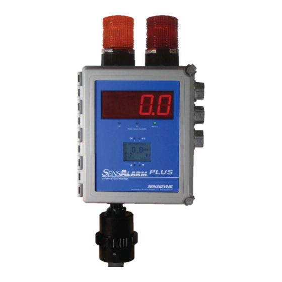
Sensidyne SensAlarm Plus User Manual (124 pages)
Universal Gas Monitoring System
Brand:
Sensidyne
| Category:
Measuring Instruments
| Size: 3 MB
Table of Contents
How to Use this Manual
2
Basic Menu Controls Guide
2
Table of Contents
3
Packing List and Notices
7
Warnings
8
1 Introduction
10
Product Versions
10
Standard Features
11
Universal Sensor Capability
11
Large Displays for Ease of Operation
11
Non Intrusive Operation
11
Transportable Calibration
11
Predictive Failure
11
AC & External DC Power Capability
11
Factory Installed Options
12
Test-On-Demand™ Gas Generator
12
Remote Sensor Operation
12
Communication Options
12
Dual Strobes
12
Internal 30 Minute Battery Backup
12
Sensalarm Plus Components
13
Sensor Interface Assembly
13
Sensalert Plus Sensor
13
Test-On-Demand
13
Sensor Holder
13
Rainshield
13
Calibration Plug Assembly
13
Liquid Crystal Display and Magnetic Controls
15
Sensor Types
16
Sensalarm Plus Housing
17
Sensalarm Plus Power Available LED (3)
17
Red Strobe
17
Amber Strobe (Option)
18
Sounder
18
Conforms to ISA Alarm Sequence 3A
18
Reset Button
18
Electronics Modules
19
Display PCA
20
LED Display (4-Digit) PCA
20
Power Assembly TB1, TB2
20
Barrier PCA
21
AC Power Supply
21
Main PCA
21
2 Installation
22
Location
22
Fire or Other Code Compliance Issues and Annunciation Requirements
22
Monitor Installation
22
AC Power
24
DC Power
25
Wiring Procedure (4-20 Ma Output)
25
Wiring Procedure (Relay Outputs)
25
Start up
26
3 Operating Functions
27
Calibration
27
Zeroing the Monitor
28
Span Calibration
29
Sensor Adjustment
33
Select Calibration Gas
34
Selecting a K-Factor
35
Selecting a Custom K-Factor
37
Tod Mode Adjustment
38
Auto Mode, Enable/Disable
39
Tod Auto Mode, Test Date/Time
40
Tod Auto Mode, Days between Tests
40
Tod Mode Adjustment, Cell Intensity
41
Tod Mode Adjustment, Output Indicators
42
4 Alarms, Faults and Relays
43
Alarms
44
Add a Relay
45
Delete a Relay
46
Enable or Disable an Alarm
46
Ascending or Descending Alarm Threshold
47
Alarm Setpoint
47
Release Offset
48
TWA Average Time Adjustment
48
Fault Functions
49
Add a Relay
50
Delete a Relay
50
Enable or Disable a Fault
51
Adjust Fault Current
51
Adjust Fault Current Delay
51
Warn Current-Relay5
52
Warn Current-Relay 5, Latching/Non-Latching
52
Warn Current - Relay 5, Enable or Disable
53
Low Current Time Adjust
53
Relay 1-Fail, Relay 2, Relay 3, Relay 4
54
Latching or Non-Latching
54
Norm Energized/ Norm De-Energized
54
Time Delay
55
Horn - Relay 6
56
Latching or Non-Latching
56
Timeout (Enabled/Disabled)
56
Time Delay
57
Timeout Delay
57
Red Strobe - Relay7, Amber Strobe-Relay8
58
Latching or Non-Latching
58
Norm Energized/ Norm De-Energized
59
Time Delay
59
5 Menu Structure & Map
60
Basic Guide to Using the Menu System
60
Sens
60
Main Menu Screen
60
Main Menu (Screens)
87
As Shown on the Example Display to the Right, the Top Level (Main) Menu Allows the Selection of Several Submenus, Documented Below. Selecting OK Brings up the Submenus
87
Calibration Mode
87
Zero Monitor
87
Calibrate
87
Set Cal Gas Concentration
88
Maintenance Mode
88
Data Review
88
Calibration Info
89
Sensor Status
89
Sensor Data
89
Active Alarms/Faults
89
Fault Currents
90
Fault Current Delay
90
Rly Alm Fault Config
90
Tod Review
91
Communication Review
91
Firmware Review
91
Test-On-Demand (Main Menu)
92
System Configuration
92
Self Test
92
Alarm Settings
93
4/20 Ma Adjustment
98
Adjust Date/Time
99
Communication Setup
99
Tod Mode Adjustment
100
Sensor Adjustment
100
Set Password
101
Reset Defaults
102
Set Monitor Tag
103
6 Product Numbers & Parts List
104
Monitors
104
Sensors
104
Options & Accessories
104
Spare Parts
104
Calibration Equipment
105
Zero Calibration Gases
105
Calibration Gases
105
7 Appendix A: Declaration of Conformity
107
8 Appendix B: Specifications
108
9 Appendix C: Troubleshooting Guide
109
10 Appendix D: Tuv Certification
111
11 Appendix F: Returned Material Authorization
112
12 Appendix G: Configuration Reference
113
13 Appendix H: Mounting Drawings
119
Advertisement
Advertisement
Related Products
Sensidyne Sensalert
Sensidyne SENSALARM FLEX
Sensidyne SENSALERT IR
Sensidyne SensAir
Sensidyne 80570
Sensidyne AP-20S
Sensidyne Gilian AIRCON-2
Sensidyne Categories
Water Pump
Test Equipment
Measuring Instruments
Transmitter
Gas Detectors
More Sensidyne Manuals
Login
Sign In
OR
Sign in with Facebook
Sign in with Google
Upload manual
Upload from disk
Upload from URL