Philips BDP3306/F7 Service Manual
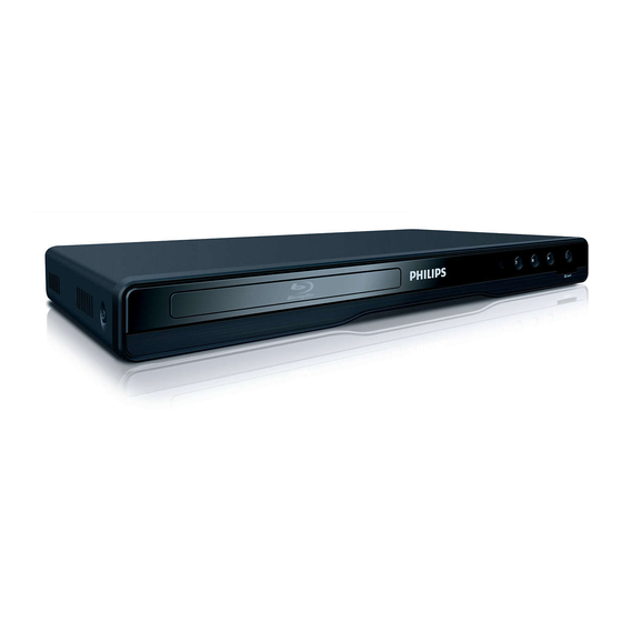
Blu-ray disc player
Hide thumbs
Also See for BDP3306/F7:
- User manual (68 pages) ,
- Quick start manual (9 pages) ,
- Specifications (3 pages)
Table of Contents
Advertisement
Quick Links
Download this manual
See also:
User Manual
Advertisement
Table of Contents

Related Manuals for Philips BDP3306/F7


Summary of Contents for Philips BDP3306/F7
- Page 1 SERVICE MANUAL BLU-RAY DISC PLAYER BDP3306/F7...
-
Page 2: Table Of Contents
IMPORTANT SAFETY NOTICE Proper service and repair is important to the safe, reliable operation of all P&F Equipment. The service procedures recommended by P&F and described in this service manual are effective methods of performing service operations. Some of these service special tools should be used when and as recommended. -
Page 3: Specifications
SPECIFICATIONS 1-1-1 E5W21SP... -
Page 4: Laser Beam Safety Precautions
LASER BEAM SAFETY PRECAUTIONS This BD player uses a pickup that emits a laser beam. Do not look directly at the laser beam coming from the pickup or allow it to strike against your skin. The laser beam is emitted from the location shown in the figure. When checking the laser diode, be sure to keep your eyes at least 30 cm away from the pickup lens when the diode is turned on. -
Page 5: Important Safety Precautions
IMPORTANT SAFETY PRECAUTIONS Product Safety Notice Also check areas surrounding repaired locations. J. Be careful that foreign objects (screws, solder Some electrical and mechanical parts have special droplets, etc.) do not remain inside the set. safety-related characteristics which are often not K. - Page 6 Safety Check after Servicing Examine the area surrounding the repaired location for damage or deterioration. Observe that screws, parts, and wires have been returned to their original positions. Afterwards, do the following tests and confirm the specified values to verify compliance with safety standards. 1.
-
Page 7: Standard Notes For Servicing
STANDARD NOTES FOR SERVICING Circuit Board Indications Pb (Lead) Free Solder 1. The output pin of the 3 pin Regulator ICs is When soldering, be sure to use the Pb free solder. indicated as shown. How to Remove / Install Flat Pack-IC Top View Bottom View 1. - Page 8 3. The flat pack-IC on the CBA is affixed with glue, so With Soldering Iron: be careful not to break or damage the foil of each 1. Using desoldering braid, remove the solder from pin or the solder lands under the IC when all pins of the flat pack-IC.
- Page 9 2. Installation With Iron Wire: 1. Using desoldering braid, remove the solder from 1. Using desoldering braid, remove the solder from all pins of the flat pack-IC. When you use solder the foil of each pin of the flat pack-IC on the CBA flux which is applied to all pins of the flat pack-IC, so you can install a replacement flat pack-IC more you can remove it easily.
- Page 10 Instructions for Handling Semi- conductors Electrostatic breakdown of the semi-conductors may occur due to a potential difference caused by electrostatic charge during unpacking or repair work. 1. Ground for Human Body Be sure to wear a grounding band (1 MΩ) that is properly grounded to remove any static electricity that may be charged on the body.
-
Page 11: Cabinet Disassembly Instructions
CABINET DISASSEMBLY INSTRUCTIONS 1. Disassembly Flowchart Note: (1) Identification (location) No. of parts in the figures This flowchart indicates the disassembly steps to gain (2) Name of the part access to items to be serviced. When reassembling, (3) Figure Number for reference follow the steps in reverse order. - Page 12 : See Reference Note 4. CN6803 (S-7) [9] BD Mechanism Assembly * (L-1) [10] BD Main CN101 CBA Unit * (S-8) (L-1) CN302 (L-2) [2] Tray Panel (S-8) Assembly [3] Front Unit CN301 [8] Rear Panel * Fig. D2 (S-4) (S-5) (S-6) [4] Front CBA...
- Page 13 3. How to Eject a Disc When a disc cannot be removed due to malfunction or when an unplayable disc is inserted, follow the procedure below to remove the disc. Procedure A 1. Unplug the AC power cord and then plug it in. 2.
-
Page 14: How To Initialize The Blu-Ray Disc Player
HOW TO INITIALIZE THE BLU-RAY DISC PLAYER To put the program back at the factory-default, initialize the BD player as the following procedure. Note: • By initializing, network is reset to disconnected state and “Network Service Disclaimer” appears on the screen. -
Page 15: Firmware Renewal Mode
FIRMWARE RENEWAL MODE Note: The file extension of the available firmware is The appearance shown in (*1) of Fig. b is “b40”. described as follows: 1. Turn the power on and remove the disc on the tray Appearance State and close the tray. Loading Disc Loading the disc 2. - Page 16 How to Verify the Firmware Version 1. Turn the power on. 2. Remove the disc on the tray and close the tray. 3. Press [ ] (skip up), [1], [2], and [3] buttons on the remote control unit in that order. Fig.
- Page 17 FIRMWARE RENEWAL MODE (for User) Disc/USB Memory Stick/SD Card Update 1. Press [ ] button to display Setup menu. 7. Firmware loading starts. Fig. h will appear on the screen. LED of “POWER ON” flashes. 2. Select Setup - Advanced Setup - Software Update.
- Page 18 Network Update 1. Press [ ] button to display Setup menu. 8. Updating starts automatically. Fig. n will appear on the screen. 2. Select Setup - Advanced Setup - Software Update - Network. Software Update 3. When “Yes” is chosen, the screen appears in Fig. j 1.
-
Page 19: Adjustment Instructions For Bd Main Cba Or Bd Mechanism Assembly Replacement
ADJUSTMENT INSTRUCTIONS FOR BD MAIN CBA OR BD MECHANISM ASSEMBLY REPLACEMENT When replacing either BD Main CBA or BD Mechanism Assembly, the unique OPU DATA of the BD Mechanism needs to be written into the BD Main CBA. Follow the procedure below for OPU DATA write operation. Equipments: •... - Page 20 Caution: • Make sure the FFC cable is inserted in the proper direction so the Pin 1 of COMTOOL jig relay board and Pin 1 of BD MAIN CBA connector is connected. Location of Pin 1 on BD Main CBA 1pin Pin 1 is located on the left side •...
- Page 21 4. OPU DATA WRITE 4-1. Connect the unit’s AC power cord. Wait for about 30 seconds until the unit is in standby mode. 4-2. Double click on the [OpuDataWriter.exe] shortcut on the desktop to start the application. 4-3. Application start screen appears. Select the assigned connection port of [USB Serial Port] for the [COM PORT] field located at the right corner of the screen.
- Page 22 4-6. Data write begins. While writing data, the Status Display message will change. Status Display SEND LD PAR 4-7. [OK] appears in the Status Display if data write has been completed successfully. If error occurs: • If an error occurs, the screen changes to a red display. In such case, close the window and then unplug the unit AC power cord.
- Page 23 Error Code Error Code Error Description Start word error The first letter entered for [LOADER S/N] does not match. [ReadBackup]Drive Mount error Cannot mount the drive set for [ReadBackup] folder. [Transfer]Drive Mount error Cannot mount the drive set for [Transfer] folder. [OpuData]Drive Mount error Cannot mount the drive set for [OpuData] folder.
- Page 24 Error Code Error Description 2042 LdParamClear ERROR0 Cannot initialize LD Parameter. 2043 LdParamClear ERROR1 Cannot initialize LD Parameter. 2044 LdParamClear TIME OUT Cannot initialize LD Parameter (TimeOut). 2051 IopSet NG Iop Set Error 2052 IopSet ERROR0 Iop Set Error 2053 IopSet ERROR1 Iop Set Error 2054...
-
Page 25: Troubleshooting
TROUBLESHOOTING FLOW CHART NO.1 The power cannot be turned on. See FLOW CHART No.2 <The fuse blows out.> Is the fuse normal? Is normal state restored when once unplugged Check if there is any leak or short-circuiting on the power cord is plugged again after several seconds? primary circuit component, and service it if defective. - Page 26 FLOW CHART NO.6 No operation is possible from the remote control unit.(Operation is possible from the unit.) Is 3.3V voltage supplied to Pin(2) of RS1201 Check EV+11V line on Power Supply CBA and (remote control receiver) ? service it if defective. Or replace BD Main CBA Unit. Is the "L"...
-
Page 27: Error Message
ERROR MESSAGE Note: Only error messages for the unit’s corresponding media will appear. Disc Error - - Please eject the disc. - - Playback feature may not be available on this Disc. Error Message Disc Error Disc Error - - Please eject the disc. - - Playback feature may not be available on this Disc. - Page 28 Error Message Cannot Confirm Firmware It is not possible to confirm the firmware version. Version Please contact our support center. Error detected. File may be corrupted. Please download software again. Firmware Update Error Error detected. (Update File Error) Please confirm whether it is SD Memory Card that corresponds to software update.
-
Page 29: Block Diagrams
BLOCK DIAGRAMS System Control Block Diagram 1-11-1 E5W21BLS... - Page 30 Digital Signal Process 1 Block Diagram 1-11-2 E5W21BLD1...
- Page 31 Digital Signal Process 2 Block Diagram 1-11-3 E5W21BLD2...
- Page 32 Video/Audio Block Diagram TMDS SERIALIZER TMDS ENCODER HDCP CIPHER/ ENCRYPTOR CONTROLLER AUDIO 1-11-4 E5W21BLV...
- Page 33 Power Supply Block Diagram 1-11-5 E5W21BLP...
-
Page 34: Schematic Diagrams / Cba And Test Points
SCHEMATIC DIAGRAMS / CBA AND TEST POINTS Standard Notes WARNING Many electrical and mechanical parts in this chassis have special characteristics. These characteristics often pass unnoticed and the protection afforded by them cannot necessarily be obtained by using replacement components rated for higher voltage, wattage, etc. - Page 35 LIST OF CAUTION, NOTES, AND SYMBOLS USED IN THE SCHEMATIC DIAGRAMS ON THE FOLLOWING PAGES: 1. CAUTION: FOR CONTINUED PROTECTION AGAINST FIRE HAZARD, REPLACE ONLY WITH THE SAME TYPE FUSE. ATTENTION: POUR UNE PROTECTION CONTINUE LES RISQES D'INCELE N'UTILISER QUE DES FUSIBLE DE MÊME TYPE. RISK OF FIRE-REPLACE FUSE AS MARKED.
- Page 36 Power Supply Schematic Diagram CAUTION ! CAUTION ! NOTE: For continued protection against fire hazard, Fixed voltage (or Auto voltage selectable) power supply circuit is used in this unit. The voltage for parts in hot circuit is measured using replace only with the same type fuse. If Main Fuse (F1000) is blown , check to see that all components in the power supply hot GND as a common terminal.
- Page 37 Front Schematic Diagram RS1201 KSM-712TC2M (REMOTE SENSOR) FRONT CBA R1206 6.8K C1201 TO BD MAIN CBA R1202 R1210 CN1201 UNIT CN6803 R1201 1 GND 3.4(0) 2 PLAY-LED D1202 3 POWER-LED D1201 204-15/T2C3-4NQA 204-15/T2C3-4NQA 4 KEY-1 POWER PLAY 5 EV+3.3V R1212 6 REMOTE 7 P-ON+5V (5.0)
- Page 38 SD Schematic Diagram TO BD MAIN CBA SD CBA CN1402 UNIT CN6405 USBDP USBDN BUS-POWER WIRELESS CN1401 LAN MODULE USBDP USBDN BUS-POWER R1409 TO BD MAIN CBA UNIT CN6401 CN1405 SDDAT2 R1410 CN1404 (SD CARD SLOT) SDDAT3 SDDAT3 3 GND P-ON+3.3V 4 D+3.3V SDCLK...
- Page 39 BD Main 1 Schematic Diagram 1 NOTE: The order of pins shown in this diagram is different from that of actual IC6001. IC6001 is divided into nine and shown as IC6001 (1/9) ~ IC6001 (9/9) in this BD Main Schematic Diagram Section. CONTINUE BD MAIN 2 THERMO...
- Page 40 BD Main 2 Schematic Diagram 1 NOTE: The order of pins shown in this diagram is different from that of actual IC6001. IC6001 is divided into nine and shown as IC6001 (1/9) ~ IC6001 (9/9) in this BD Main Schematic Diagram Section. BD MAIN CBA UNIT IC6001(2/9) MN2WS0062AFF-B...
- Page 41 BD Main 3 Schematic Diagram 1 NOTE: The order of pins shown in this diagram is different from that of actual IC6001. IC6001 is divided into nine and shown as IC6001 (1/9) ~ IC6001 (9/9) in this BD Main Schematic Diagram Section. BD MAIN CBA UNIT CONTINUE BD MAIN 8...
- Page 42 BD Main 4 Schematic Diagram 1 NOTE: The order of pins shown in this diagram is different from that of actual IC6001. IC6001 is divided into nine and shown as IC6001 (1/9) ~ IC6001 (9/9) in this BD Main Schematic Diagram Section. BD MAIN CBA UNIT IC6001(4/9) MN2WS0062AFF-B...
- Page 43 BD Main 5 Schematic Diagram 1 NOTE: The order of pins shown in this diagram is different from that of actual IC6001. IC6001 is divided into nine and shown as IC6001 (1/9) ~ IC6001 (9/9) in this BD Main Schematic Diagram Section. BD MAIN CBA UNIT IC6001(5/9) MN2WS0062AFF-B...
- Page 44 BD Main 6 Schematic Diagram 1 NOTE: The order of pins shown in this diagram is different from that of actual IC6001. IC6001 is divided into nine and shown as IC6001 (1/9) ~ IC6001 (9/9) in this BD Main Schematic Diagram Section. BD MAIN CBA UNIT CONTINUE BD MAIN 8...
- Page 45 BD Main 7 Schematic Diagram 1 NOTE: The order of pins shown in this diagram is different from that of actual IC6001. IC6001 is divided into nine and shown as IC6001 (1/9) ~ IC6001 (9/9) in this BD Main Schematic Diagram Section. VIDEO SIGNAL AUDIO SIGNAL CONTINUE...
- Page 46 BD Main 8 Schematic Diagram 1 NOTE: The order of pins shown in this diagram is different from that of actual IC6001. IC6001 is divided into nine and shown as IC6001 (1/9) ~ IC6001 (9/9) in this BD Main Schematic Diagram Section. CONTINUE BD MAIN CBA UNIT BD MAIN 2...
- Page 47 BD Main 9 Schematic Diagram CONTINUE BD MAIN CBA UNIT BD MAIN 8 SAFETY1 SAFETY2 R6805 R6873 R6854 C6809 R6852 1000P 100K R6863 R6826 R6828 D6801 1SS400ST R6830 R6831 R6864 Q6802 MMBTSC3875G R6833 (BUFFER) CONTINUE BD MAIN 10 SAFETY1 R6865 TO FRONT CBA CN1201 CN6803...
- Page 48 BD Main 10 Schematic Diagram CONTINUE BD MAIN 7 PRMVS BD MAIN CBA UNIT PRMHS PRMCLK CONTINUE CONTINUE BD MAIN 7 BD MAIN 6 PRMC(0-11) SCL3 PRMY(0-11) SDA3 C6437 C6439 C6441 R6584 R6580 C6442 C6443 C6445 R6582 R6589 C6447 C6449 L6401 JK6401 (HDMI-CONNECTOR)
- Page 49 BD Main 11 Schematic Diagram 1 NOTE: The order of pins shown in this diagram is different from that of actual IC6001. IC6001 is divided into nine and shown as IC6001 (1/9) ~ IC6001 (9/9) in this BD Main Schematic Diagram Section. BD MAIN CBA UNIT CONTINUE BD MAIN 6...
- Page 50 Power Supply CBA, Front CBA & SD CBA Top View CAUTION ! Fixed voltage (or Auto voltage selectable) power supply circuit is used in this unit. If Main Fuse (F1000) is blown , check to see that all components in the power supply Not used Front CBA circuit are not defective before you connect the AC plug to the AC power supply.
- Page 51 Power Supply CBA, Front CBA & SD CBA Bottom View CAUTION ! Fixed voltage (or Auto voltage selectable) power supply circuit is used in this unit. If Main Fuse (F1000) is blown , check to see that all components in the power supply Not used Front CBA circuit are not defective before you connect the AC plug to the AC power supply.
-
Page 52: Waveforms
WAVEFORMS JK6602 (VIDEO OUT) VIDEO-CVBS VIDEO-CVBS 0.5V 0.5V 20µs JK6602 (AUDIO(L) OUT) AUDIO(L) AUDIO(L) 0.5ms 0.5ms JK6602 (DIGITAL AUDIO OUT) SPDIF SPDIF 0.1µs NOTE: Input Signal (DVD) VIDEO: 75% COLOR BAR AUDIO: 1KHz, 0dB 1-13-1 B4NWF... -
Page 53: Wiring Diagram
WIRING DIAGRAM BUS-POWER USBDN USBDP SDDAT2 EXPB(+) SDDAT3 EXPB(-) EXPA(+) EXPA(-) P-ON+3.3V SDCLK THERMO SDDATO SDDAT1 A+8V BD-LD TEST-V LD-TYPE CD-LD AVCC PD-LD LDON LDD-SDATA DVD-LD LDD-SCLK DSEN P-ON+5V REMOTE AVCC EV+3.3V FPIO1 KEY-1 POWER-LED PLAY-LED RF(-) RF(+) VC-PD LOAD(-) LOAD(+) TRAY-IN VH(+) -
Page 54: Lead Identifications
LEAD IDENTIFICATIONS MIP2E4D SL431A-AT 1: Control 2: Source 3: Drain 1 2 3 R A K 2SA1980SFG MMBTSC3875G PS2561A-1(W) Note: 1: Anode A: Anode 2: Cathode K: Cathode 3: Emitter E: Emitter 4: Collector C: Collector B: Base R: Reference G: Gate D: Drain S: Source... -
Page 55: Exploded Views
EXPLODED VIEWS Cabinet 2L082 2L082 2L085 2L082 2L081 2L070 2L049 2L083 BD Main CBA Unit 2L027 F1000 2L058 Power Supply CBA 2L027 2L050 SD CBA A20-A See Electrical Parts List for parts with this mark. Front CBA Some Ref. Numbers are not in sequence. - Page 56 Packing Upper Side Lower Side X2-A A20-C S1-A S1-B A20-B Some Ref. Numbers are not in sequence. 1-16-2 E5W21PEX...
-
Page 57: Mechanical Parts List
OWNERS MANUAL E5W21UD 1VMN30733 X2-A QUICK GUIDE E5W21UD 1VMN30734 BATTERY GR03M XB0M371GLP01 ACCESSORY BAG E5700UD 0VM415576C AV CORD 1500/BLACK WPZ1520TM003 REGISTRATION CARD(PHILIPS) E1U00UD 1VMN30775 REMOTE CONTROL UNIT NB549UD NB549UD BROCHURE (PHILIPS) A01N2UH 1EMN26419 NETFLIX GUIDE E5PG0UD 1VMN28453A VUDU SHEET E5S20UD 1VMN30133 2011/1/31 1-17-1 E5W21CA.fm... -
Page 58: Electrical Parts List
ELECTRICAL PARTS LIST PRODUCT SAFETY NOTE: Products marked with a Ref. No. Description Part No. # have special characteristics important to safety. D1003 DIODE 1N5397-B NDLZ001N5397 Before replacing any of these components, read D1004 DIODE 1N5397-B NDLZ001N5397 carefully the product safety notice in this service D1005 DIODE ZENER 1ZB220-ZBB NDWZ01ZB220Z... - Page 59 Ref. No. Description Part No. CHIP RES. 1/10W J 33 Ω R1411 RRXAJR5Z0330 CHIP RES. 1/10W J 33 Ω R1412 RRXAJR5Z0330 MISCELLANEOUS CUSHION E5W00UD 1VM437739 FRONT CBA Ref. No. Description Part No. FRONT CBA ---------- Consists of the following CAPACITOR C1201 CHIP CERAMIC CAP .(1608) F Z 0.1µF/50V CHD1JZ30F104...
- Page 60 Misuse of any trademarks or any other content in this manual is strictly prohibited. Funai shall aggressively enforce its intellectual property rights to the fullest extent of the law. BDP3306/F7 E5W21UD 2011-02-02...
Need help?
Do you have a question about the BDP3306/F7 and is the answer not in the manual?
Questions and answers