Table of Contents
Advertisement
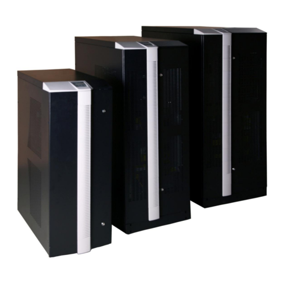
PYRAMID DSP SERIES
.
THREE PHASE IN – THREE PHASE OUT
10-120kVA
THREE PHASE IN – ONE PHASE OUT
10-40kVA
I
N
S
T
A
L
L
A
T
I
O
N
a
n
d
O
P
E
R
A
T
I
N
G
I
N
S
T
A
L
L
A
T
I
O
N
a
n
d
O
P
E
R
A
T
I
N
G
M
A
N
U
A
L
M
A
N
U
A
L
UNINTERRUPTIBLE POWER SYSTEMS
288717215
KULL.KILAV.PDSP 10-120KVA A4 ING. INF511-Y01-U727-1-00
Advertisement
Table of Contents


Need help?
Do you have a question about the PDSP31010 and is the answer not in the manual?
Questions and answers