Advertisement
OVERVIEW
System Components
This guide describes quick start connection information for the iSTAR Pro, including:
how to wire readers to RM ports and to "direct connect" Wiegand ports.
how to wire supervised inputs and dry contact relay outputs.
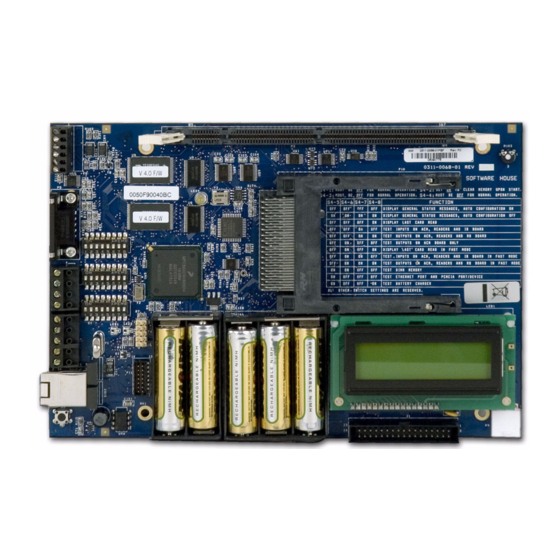
The iSTAR Pro hardware components consist of:
General Controller Module (GCM) – A general purpose board running Windows
CE. The GCM has two PCMCIA slots for an internal modem, and a second network
interface card or a compact flash card. There is an LCD panel to display the current
status and to use when running built in diagnostics. There is a panel of batteries to
retain the data memory in the event of a power failure.
The iSTAR Pro GCM can interface with one or two ACM modules.
Access Control Modules (ACM) – A special purpose access control board that
communicates with the GCM and provides inputs, outputs, and readers. An iSTAR
Pro can contain up to two ACMs that interface with Wiegand signaling and ABA
(magnetic) signaling devices.
Optional 12 VDC@ 5A Power Supply.
Controllers - with Power Supplies
iSTAR Pro
Quick Start
Installation Guide
Document Part Number UM-212
Version C0
January 2007
1
Advertisement
Table of Contents

Related Manuals for Software House iSTAR PRO

Summary of Contents for Software House iSTAR PRO
-
Page 1: Quick Start
Document Part Number UM-212 January 2007 OVERVIEW This guide describes quick start connection information for the iSTAR Pro, including: how to wire readers to RM ports and to “direct connect” Wiegand ports. how to wire supervised inputs and dry contact relay outputs. - Page 2 STAR-ACM8-WA Add-on Access Control Module II (ACM II) Includes cable assembly and relay board for an additional 8 Wiegand or 8 RM readers. Each iSTAR Pro can support up to 2 ACM IIs. STARGC-64MBA General Controller Module II (GCM II), with 64 MB RAM...
- Page 3 Overview GCM Module FIGURE 2. Photograph of iSTAR Pro GCM ACM Module FIGURE 3. Photograph of iSTAR Pro ACM...
- Page 4 This section describes the power requirements for the iSTAR Pro. AC Power The iSTAR Pro input power rating is 100 - 240 VAC, 2.3A max, 47-63 Hz. The system current draw is 2.3A @100VAC or 1.1A max @240VAC, 47-63Hz. To connect AC power: 1.
- Page 5 Caution: Risk of explosion if battery is replaced by an incorrect type. Dispose of used batteries according to the instructions. iSTAR Pro batteries are packaged separately and should be installed in the battery backup sockets at the bottom of the GCM.
-
Page 6: Network Connection
LED2 indicates the Ethernet Link signal and LED1 displays the Receive Data signal. NOTE This document applies to both C•CURE® 800 and C•CURE® 9000 iSTAR Pro controllers, unless noted otherwise. Version 1.0 of C•CURE 9000 does not support multiple controller clusters, serial ports, or RAS connections. -
Page 7: Dialup Connection
GCM General Control Module Dialup Connection 1. Connect P6 to the iSTAR modem as shown in Table 2. TABLE 2. DB25-to-P6 Pin Connections Modem iSTAR DB25 Pin Modem DB25 Signal P6 Pin iSTAR P6 Signal 2. Connect the host modem to a COM Port. 3. -
Page 8: Diagnostic Session
DIP Switch S1 is factory set for RS232 on P6. Do not change. DIP Switch S4 is used to control diagnostics, clear memory and to display card reads in hexadecimal. See the iSTAR Pro door map for more detailed information about running diagnostics. -
Page 9: Lcd Panel
GCM General Control Module LCD Panel The LCD panel will display various status information, such as the connection status to the host, and various diagnostic functions. If the LCD panel is difficult to read, adjust the contrast using the potentiometer at the upper right section of the GCM. -
Page 10: Acm - Access Control Module(S)
ACM - Access Control Module(s) ACM - ACCESS The ACM (Access Control Module) provides the Readers, Inputs and Outputs that are used in access control. An iSTAR Pro can contain either one or two ACMs. CONTROL MODULE(S) Figure 5 shows the components, switches, and LEDs described in this guide. - Page 11 ACM - Access Control Module(s) The STARn connectors are not keyed so it is possible to reverse the signals. If the ground connector (pin 4) is connected to +12 VDC (pin 1), damage to the power supply or the RM could result. The reader number is determined by a hexadecimal switch on the RM, not by the Port into which the reader is plugged.
-
Page 12: Led And Beep Control
ACM - Access Control Module(s) LED and Beep Control Switch 3 (S3) on the ACM controls the reader LED display and whether the reader beeps on a card read. TABLE 6. S3 LED and Beep Control S3-1 S3-2 S3-3 LED Control LED control Beep control The LED control is for read heads connected to the Wiegand (WG) ports. - Page 13 ACM - Access Control Module(s) 2 Wire (Red and Green) There are two instances of External Bi-color; two wire and one wire. With two wire, the Red and Green LED drives are wired as shown in Figure 6 FIGURE 6. External Bi-color (2 wire) 1 Wire (Yellow) With one wire, the Yellow drive is wired as shown in Figure 7 FIGURE 7.
- Page 14 Green LED when the signal is high. If the Yellow LED drive is oscillating, the Red and Green LEDs will oscillate and it will appear to the human eye that the LED is Yellow. The iSTAR Pro will oscillate the Yellow drive at 1 KHz when a Yellow LED display is required.
- Page 15 ACM - Access Control Module(s) One Wire (A, B, C) FIGURE 9. One Wire (A,B,C) LED control Beep Control Settings S3-3 Off - Do not Beep on card read. S3-3 On - Beep on card read.
- Page 16 ACM - Access Control Module(s) Inputs The wiring of supervised inputs is shown in the next two figures. Note that the resistor network is different for NO and NC switches. Normally Open (NO) Wiring Normally Closed (NC) Wiring NOTE To comply with UL requirements, use shielded, minimum 22 AWG stranded, twisted pair cable for monitor points, DSMs, and REXs.
- Page 17 ACM - Access Control Module(s) Fail Secure Wiring Fail Safe Wiring Use the C•CURE Administration application to configure the output as Normally Energized for the Fail Safe case.
- Page 18 STARn connector. This function is provided for compatibility with older iSTARs. If an iSTAR Classic is being ported to the iSTAR Pro, there are now eight RM ports per ACM instead of four. LED and Beep See “LED and Beep Control” on...
- Page 19 ACM - Access Control Module(s)
- Page 20 Information about other products furnished by Software House is believed to be accurate. However, no responsibility is assumed by Software House for the use of these products, or for an infringement of rights of the other companies that may result from their use.
Need help?
Do you have a question about the iSTAR PRO and is the answer not in the manual?
Questions and answers