
Related Manuals for Software House PSX-NL4

Summary of Contents for Software House PSX-NL4
- Page 1 PSX-NL4 FOUR PORT NETWORK MODULE INSTALLATION AND OPERATION www.swhouse.com P03-037 revAO3...
-
Page 2: Table Of Contents
2 .3 Setting Up the PSX-NL4 for use with the MSM-200 multi-site manager . . . . . . . . . . . . . . -
Page 3: Notes And Warnings
Notes and Warnings Symbol Definitions Regulatory Information The following symbols are used throughout this manual The following equipment discussed within this manual has been tested to the following standards: This symbol is intended to alert the installer of • UL 294, UL 603, UL 1076 shock hazards within the enclosure . -
Page 4: Introduction
The PSX-NL4 module is a networking appliance which may be used with the PSX product line . The PSX-NL4 is used to monitor power supply system status over a local or wide area network . When used with a PSX DC system, the PSX-NL4 will allow limited control of the power system and provide values on demand for power supply output voltage, operational fault status, battery charging voltage, battery charging current, and fire alarm input status . -
Page 5: Section 1 - Installation
1 .1 .1 Mounting the PSX-NL4 Network Communication Accessory Use the following procedure when mounting an PSX-NL4 Network Communication Accessory to an enclosure . 1 . Locate the appropriate mounting holes in the enclosure and snap the four standoffs provided into the holes . -
Page 6: Psx-Nl4 Network Communication Accessory Overview
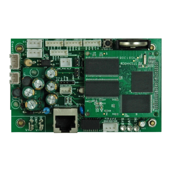
PSX-NL4 - Input V+ & V- (J1 & J3) PSX-NL4 - Event1 Input Invert Jumper (J8) This is the main power input for the PSX-NL4 board . This input accepts 8 to 30VDC ONLY (Observe the polarity care- This jumper inverts the action of the Event 1 Input . See sec- fully) from any power supply . - Page 7 This is the coin cell battery for maintaining the clock when The long red lead connects in-line with the current to be all power is removed from the PSX-NL4 . The battery type is measured toward the more positive side of the current flow .
-
Page 8: Connecting The Psx-Nl4 Network Communication Accessory
Connect one end of the SPI cable to one of the "Device" con- INPUT (V+ & V-) fastons . The voltage of this source must nectors on the PSX-NL4 . Connect the other end to the Data- be between 8 and 30VDC and should be backed up with a... - Page 9 PSX-NL PSX PS Input V+ V- V- alternate connection (only PSX-150/250 models) Figure 1.4 - Power the PSX-NL4 off the PSX DC1 terminals PSX-D8 PSX-NL PSX PS Input Figure 1.5 - Do not power off another accessory board's output...
- Page 10 Connect one end of the ADC cable to the ADC1 input on the the "H1" connector is for the battery connected to PSX #1 . PSX-NL4 board . Cut off the other end of the ADC cable and the "H2" connector is for PSX #2 .
- Page 11 1.3.8 Wiring the Control Outputs Connect one end of the Control Output cable to the Control Outputs connector on the PSX-NL4 . Cut off the other end of the control output cable . The wire going to the pin on the connector labeled "FLT"...
-
Page 12: Section 2 - Initial Configuration
Section 2 – Initial Configuration The PSX-NL4 is shipped with DHCP enabled as default . If the PSX-NL4 is being connected to a DCHP network, or if the PSX-NL4 has been preconfigured for your network, this section may be skipped . If the network is not DHCP, the PSX-NL4 must have the IP settings configured . -
Page 13: Configuring The Psx-Nl4
Note that if the PSX-NL4 has been connected to a DHCP network, the IP address will be as assigned by the DHCP server . Use the Network a Tool at www .lifesafetypower .com to find the correct IP address . - Page 14 PSX-NL4 Network Module - Operation Manual Figure 2.4 - Typical PSX-NL4 Home Page...
- Page 15 PSX-NL4's IP address before logging into the PSX-NL4 board . The port number used by the PSX-NL4 can also be set in the Port# field . By default the PSX-NL4 is set to use port 80 . To disable HTTP access and only allow access via HTTPS, check the "Disable HTTP"...
- Page 16 PSX-NL4 . The NTP Server field allows you to enter an NTP server for automatic setting of the time and date via the internet . The PSX-NL4 must be configured for internet access before this setting will work . Enter up to two NST servers in the fields provided (available from websites such as NIST) .
- Page 17 The SNMP Trap Receiver IP and Port settings should be set to the proper address for the SNMP Trap receiver . Click the "Submit" button and reboot the PSX-NL4 for the settings to take effect . The SNMP Inform Log may be seen by clicking the "Show Inform Log"...
- Page 18 2.2.7 Remote VPN Settings Below the Email Test section is the VPN Settings section (See Figure 2 .7) . When using the PSX-NL4 with an MSM-200 which is not within the same local network, the IP address, User Name, and Password for the MSM-200 may be entered here . Click "Submit" for the settings to take effect .
- Page 19 Manager-level users have access to all areas of the PSX-NL4 except for the Configure page . • Guest Guest-level users may only view information on the PSX-NL4 screens . No changes can be made and none of the control features are available .
- Page 20 The "Select Occurrences to Report" block of the Reporting page allows the setting of the number of history events which will be in- cluded in the report file attached to the alert email (See Figure 2 .8) . The PSX-NL4 records a snapshot of device parameters at the time period selected on the Configure page .
- Page 21 Installation and Operation Figure 2.8 - Typical Reporting Page...
-
Page 22: Setting Up The Psx-Nl4 For Use With The Msm-200 Multi-Site Manager
The bottom section of the Reporting page contains the devices and parameters selection area (See Figure 2 .8) . Any connected devices will show here, along with a section for the PSX-NL4 itself . To include these devices in the email alert report, check the box to the right of the device name in the heading for the device . -
Page 23: Section 3 - Using The Psx-Nl4
Home page is broken into several sections as follows . 3.1.1 Basic Site Information The top portion of the PSX-NL4 Home page lists the Site ID (as programmed on the Configure page) as well as the system time and date (Figure 3 .1) . - Page 24 3.1.3 Network Connected Devices Section The bottom of the home page shows the devices connected to the Device connectors of the PSX-NL4 with a SPI cable . Each device will display a photo of the device and the model number . The Device ID is a unique number given by the PSX-NL4 to each device .
-
Page 25: Accessing And Programming Connected Devices
PSX-NL4's interface . Note that programming these parameters changes the operation of the device itself . To access the page for a device, click on the photo of the device in the PSX-NL4 Connected Devices section of the home page . - Page 26 Device This is the identifying label for the PSX device . This label is given by the PSX-NL4 and is not user settable . The first PSX connected to a device input is labeled FP1 and the second is labeled FP2 . Up to two PSX power supplies may be connected to an PSX-NL4 board .
- Page 27 If enabled, this will display a bar graph indicating the estimated battery condition of the battery connected to the PSX . Once the battery is connected and the PSX-NL4 detects current flow, an enable/disable button will appear at the bottom of the Battery Status area .
- Page 28 The Battery Test section allows the user to test the actual run-time of a system with the installed battery set . (Figure 3 .2, page 21) . This test may be run manually or may be scheduled for a one-time automated test . If email is configured on the PSX-NL4, a report of the results can be emailed .
- Page 29 Rated Capacity Enter the battery capacity of the battery connected to the PSX . This rating is used by the PSX-NL4 to approxi- mate how much capacity is remaining in the battery (if using the current sensor to monitor battery health) .
- Page 30 (by disconnecting both red leads on the current sensor) . Click "OK", and the PSX-NL4 will self-calibrate to the current sensor . Ensure the current reading on the home page is zero (or very close to zero) before reconnecting the current sensor's red leads .
-
Page 31: Using The Tools Page
Rebooting the PSX-NL4 Board The "Reboot" section is on the top right of the Tools page (See Figure 3 .9) . To reboot the PSX-NL4, click the "Submit" button . Once the "Confirm Reboot" message appears in the Message window, click the OK button to Confirm the reboot . The rebooting process will take approximately 1 minute, during which you will lose communication with the PSX-NL4 . -
Page 32: Understanding The Email Report
3 .4 Understanding The Email Report The report file sent by email by the PSX-NL4 is sent as an unformatted .CSV file . Many programs, such as Microsoft Excel, will import a .CSV file to allow viewing of the data (See Figure 3 .10) . - Page 33 Installation and Operation PAGE INTENTIONALLY LEFT BLANK...
-
Page 34: Appendix 1 - Software Agreement
PSX-NL4 Network Module - Operation Manual Appendix 1 – Software Agreement microcode . Regarding any of LIFESAFETY POWER INC .’s software and/or firmware LIFESAFETY POWER INC . SOFTWARE LICENSE AGREEMENT AND WARRANTY STATEMENT "Reverse Engineering" shall also mean iii) the act of producing computer program "source code"... - Page 35 Installation and Operation 4 . DISCLAIMER OF WARRANTIES . 7 . Miscellaneous . (a) “AS-IS” SOFTWARE . THE SOFTWARE (AS DEFINED IN THIS AGREEMENT) IS PRO- (a) Notice and Contact Information . LIFESAFETY POWER INC . may be contacted at the VIDED ON AN “AS IS”, “AS AVAILABLE”...
- Page 36 I n t e r n a t i o n a l C o m p a n y PSX-NL4 Network Module - Operation Manual www.swhouse.com The trademarks, logos, and service marks displayed on this document are registered in the United States [or other countries]. Any misuse of the trademarks is strictly prohibited and Tyco International Ltd. will aggressively enforce its intellectual property rights to the fullest extent of the law, including pursuit of criminal prosecution wherever necessary.
Need help?
Do you have a question about the PSX-NL4 and is the answer not in the manual?
Questions and answers