Advertisement
SERVICE
AIR CONDITIONER
E DB68-00276A(5)
ROOM AIR CONDITIONER
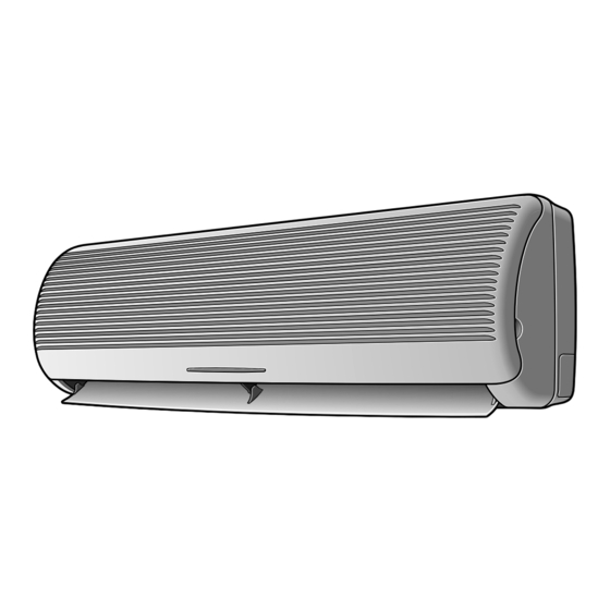
INDOOR UNIT
AQ24A2QC
AQ18A2QC
Manual
OUTDOOR UNIT
UQ24A2QC
UQ18A2QC
CONTENTS
Advertisement
Table of Contents

Related Manuals for Samsung AQ24A2QC


Summary of Contents for Samsung AQ24A2QC
-
Page 1: Table Of Contents
ROOM AIR CONDITIONER INDOOR UNIT OUTDOOR UNIT AQ24A2QC UQ24A2QC AQ18A2QC UQ18A2QC SERVICE Manual AIR CONDITIONER CONTENTS 1. Installation 2. Disassembly and Reassembly 3. Troubleshooting 4. Exploded Views and Parts List 5. Refrigerating Cycle Block Diagrams 6. Wiring Diagrams 7. Schematic Diagrams... -
Page 2: Installation
1. Installation 1-1 Refrigerant Refill Procedure • Refill an air-conditioner with refrigerant when refrigerant has been leaked at installing or using 1. Purge air(for new installation only). 2. Turn the 3-way valve clockwise to close, connect the pressure gauge(low pressure side) to the service valve, and open the 3-way valve again. - Page 3 1-2 “Pump down” Procedure • Pump down' shall be carried out when an evaporator is replaced or when the unit is relocated in another area. 1. Remove the caps from the 2-way valve and the 3-way valve. 2. Turn the 3-way valve clockwise to close and connect a pressure gauge(low pressure side) to the service valve, and open the 3-way valve again.
-
Page 4: Disassembly And Reassembly
2. Disassembly and Reassembly Stop operation of the air conditioner and remove the power cable before repairing the unit. 2-1 Indoor Unit Parts Procedure Remark Front Grille 1) Stop the air conditioner operation and block the main power. 2) Seperate tape of front panel upper. 3) Contract the second finger to the left, and right handle and pull to open the inlet grille. - Page 5 Parts Procedure Remark Ass’y Tray Drain. 1) Do “1”, above. Separate the drain hose from the extension drain hose. 2) Take the display PCB out. (Center of indoor unit) 3) Loosen two fixing screws of left and right 4) Pull tray drain out from the back body. Electrical Parts 1) Do “1”, “2”, above (Main PCB)
- Page 6 Parts Procedure Remark Fan Motor and 1) Do “1” “2” ”3” “4”, above. Cross Fan 2) Loosen the fixing three screws and separate the motor holder. 3) Loosen the fixing screw of fan motor. (By use of M3 wrench) 4) Separate the fan motor from the fan. 5) Separate the fan from the left holder bearing.
- Page 7 2-2 Outdoor Unit Parts Procedure Remark Cabinet 1) Turn off the unit and remove the power cable 2) Remove the top cover. 3) Remove the control box cover. 4) Unplug the ass'y cable. 5) Remove the cabi-side. 6) Remove the cabi-front. * When you assemble the parts, check if the each parts and electric connectors are fixed firmly.
-
Page 8: Troubleshooting
3. Troubleshooting 3-1 Items to be checked first 1) Is the voltage of the power correct? The input voltage shall be the rating voltage ±10%. The airconditioner may not operate properly if the voltage is out of this range. 2) Is the link cable linking the indoor unit and the outdoor unit linked properly? The indoor unit and the outdoor unit shall be linked by 6 cables. -
Page 9: Fault Diagnosis By Symptom
3-2 Fault Diagnosis by Symptom 3-2-1 No Power(completely dead)-Initial diagnosis 1) Checklist : (1) Is input voltage normal? (rating voltage ±10% range) (2) Is AC power linked correctly? (3) Are connections between primary side, secondary side of the power transformer and PCB good. (4) Is output voltage of DC regulator IC KA7812 (IC01) normal? (11VDC-12.5VDC) (5) Is output voltage of DC regulator IC KA7805 (IC02) normal? (4.5VDC-5.5VDC) 2) Troubleshooting procedure... - Page 10 3-2-2 When the Indoor Unit Fan Does Not Operate. (Initial Diagnosis) 1) Checklist : (1) Is the indoor unit fan motor properly connected with the connector (CN73)? (2) Is the AC voltage correct? (3) Is HALL IC in indoor fan motor properly connected with the connector (CN43)? (4) Is the running capacitor properly connected with the solder part of the PCB? 2) Troubleshooting procedure After unplugging out the power cord should...
- Page 11 3-2-3 When the Outdoor Unit Does Not Operate. (Initial Diagnosis) Checklist : (1) Is input voltage normal?(rating voltage ±10% range) (2) Is the set temperature of the remote control higher than room temperature in COOL mode? (3) Is the set temperature of the remote control lower than room temperature in HEAT mode? (4) Is the POWER IN connector (CN78) linked correctly? (5) Is the outdoor unit properly connected with the TERMINAL BLOCK connector(7P)? Troubleshooting procedure...
- Page 12 3-2-4 When the UP/DOWN Louver Motor Does Not Operate. (Initial Diagnosis) 1) Checklist : (1) Is input voltage normal? (rating voltage ±10% range) (2) Is the UP/DOWN louver motor properly connected with the connector (CN61)? 2) Troubleshooting procedure Remove power cord and plug in again in approx. 5 seconds. Is operating lamp blinking? Check as in the procedure "No Power parts".
- Page 13 3-2-6 If Operation By Remote Control Unit Is Impossible. (Initial Diagnosis) 1) Troubleshooting procedure Remove power cord and plug in again approx. 5 Seconds Is operation lamp blinking? Check as in the procedure “NO Power parts”. Refer to page 5-2. “...
- Page 14 MEMO...
-
Page 15: Exploded Views And Parts List
4. Exploded Views and Parts List 4-1 Indoor Unit... - Page 16 Parts List Q’TY CODE NO Description Specification Remark AQ24A2QC AQ18A2QC DB64-10173A GRILLE AIR INLET HIPS DB64-70108A PANEL CENTER DISPLAY DB63-30150A GUARD AIR FILTER DB74-10101A CLEANER FILTER ASS’Y ASS’Y DB61-10164C CASE-CLEANER FILTER DB74-10082B CARBON FILTER POLYESTER/CARBON DB74-10081A CLEANER FILTER POLYESTER/COTTON DB63-10466A...
- Page 17 4-2 Outdoor Unit 4-2-1 UQ18A2QC 13-2 14-3 14-1 15-4 14-2 15-1 15-5 13-1 15-3 15-2 12-3 12-4 12-2 12-1 18-1 18-2 13-1 18-3 18-4...
- Page 18 Parts List(18K) Q’TY CODE NO Description Specification Remark UQ18A2QC DB90-00033A ASS’Y-WELD FRONT SC-90073T DB90-20160D ASS’Y-BASE OUT SC-90073T DB67-50063A ASS’Y-FAN AS+G/F20% DB60-30020A NET FLANGE M6LF DB31-10119H MOTOR FAN OUT ASS035ZTEE DB61-20008C BASE-MOTOR SGCC-M DB94-50034A PARTITION SGCC-M DB75-30103E ASS’Y-CONDENSER ASS’Y DB90-40176B COVER-CONTROL DB64-60172B ASS’Y-CABi BACK SC-90073T...
- Page 19 4-2-2 UQ24A2QC 13-2 14-1 14-2 15-4 15-1 13-1 15-5 15-3 15-2 12-3 12-4 12-2 12-1 18-1 18-2 13-1 18-3 18-4...
- Page 20 Parts List Q’TY CODE NO Description Specification Remark UQ24A2QC DB90-10634A ASS’Y CABI FRONT SC-90073T DB90-20210A ASS’Y-BASE OUT SC-90073T DB67-50074A ASS’Y-FAN AS+G/F20% DB60-20020A BOLT SPECIAL M8 L25 DB31-10110E MOTOR FAN OUT OSME-716SRC DB95-20147A ASS’Y-MOTOR B/K SGCC-M DB94-50039A PARTITION SGCC-M DB75-30102E ASS’Y-CONDENSER ASS’Y DB90-40176B COVER-CONTROL...
- Page 21 4-3 PCB Box Parts List Q’TY Description Specification CODE NO Remark AQ24A2QC AQ18A2QC DB61-10151A CASE-CONTROL DB93-10545C ASS'Y MAIN PCB PD-Q24B1Q-02 DB93-10555C ASS'Y MAIN PCB PD-Q24B1Q-05 DB32-10008E ASS'Y THERMISTOR 103AT DB93-10599B ASS’Y PCB DISPLAY ASS’Y(edge) DB26-10065B TRANSFORMER AC230V/DC17...
-
Page 22: Refrigerating Cycle Block Diagrams
5. Refrigerating Cycle block Diagram INDOOR UNIT OUTDOOR UNIT Capillary tube Check valve 2-way valve Liquid side Capillary tube Heat Heat exchanger exchanger (Evaporator) (Condenser) Gas side 3-way valve 4-way valve Cooling Heating Compressor Gas leak check point Refrigerating cycle temperature and pressure STD Pressure Piping Temp.(˚F) Use Temp. - Page 23 6. PCB Diagrams 6-1 Main PCB(DB93-10545C):AQ24A2QC (DB93-10555C):AQ18A2QC...
- Page 24 Parts List CODE NO Description Specification Specification F701 DE32-10037A FUSE FST 250V 3.15A F701,F101 DE47-40024A HOLDER-FUSE FH-51H 7.5A IC01 DE13-20008A IC-VOLT REGU KA7812A IC01 DE62-30032A HEAT-SINK AL H25 IC01 DE60-10100A SCREW-PH M3*6 FeFzY IC02 DE13-10016A IC-VOLT REGU KA7805A CR71 C-FILM CQS 450V 1.2µF FT71 FILTER NOISE...
-
Page 25: Wiring Diagrams
7. Wiring Diagrams 7-1 Indoor Unit... - Page 26 7-2 Outdoor Unit UQ18A2QC MARK NAME MARK NAME MAGNETIC CONTACTOR TB 1, 2 TERMINAL BLOCK SOLENOID COIL FAN MOTOR FUSE(2A, 250V~) SPARK KILLER CAPACITOR 2.5/40MF X 450VAC UQ24A2QC MARK NAME MARK NAME MAGNETIC CONTACTOR TB 1,2 TERMINAL BLOCK SOLENOID COIL CRANK CASE HEATER CAPACITOR FAN MOTOR...
-
Page 27: Schematic Diagrams
8. Schematic Diagrams 8-1 Indoor Unit... - Page 28 ELECTRONICS...
Need help?
Do you have a question about the AQ24A2QC and is the answer not in the manual?
Questions and answers