Table of Contents
Advertisement
Advertisement
Table of Contents

Related Manuals for Weber SOR-3

Summary of Contents for Weber SOR-3
- Page 1 DATASHEET WEBER SOR3 OTHER SYMBOLS: RGB ELEKTRONIKA AGACIAK CIACIEK SPÓŁKA JAWNA Jana Dlugosza 2-6 Street 51-162 Wrocław www.rgbelektronika.pl Poland biuro@rgbelektronika.pl +48 71 325 15 05 www.rgbautomatyka.pl www.rgbautomatyka.pl www.rgbelektronika.pl...
- Page 2 YOUR PARTNER IN MAINTENANCE Repair this product with RGB ELEKTRONIKA ORDER A DIAGNOSIS LINEAR ENCODERS SYSTEMS INDUSTRIAL COMPUTERS ENCODERS CONTROLS SERVO AMPLIFIERS MOTORS MACHINES OUR SERVICES POWER SUPPLIERS OPERATOR SERVO PANELS DRIVERS At our premises in Wrocław, we have a fully equipped servicing facility. Here we perform all the repair works and test each later sold unit.
-
Page 3: User's Manual Sor
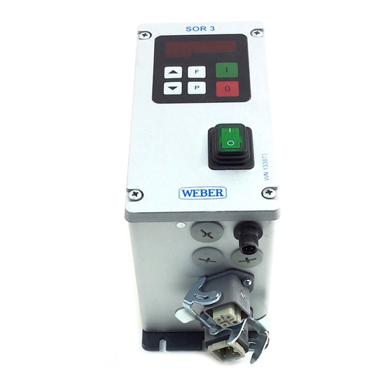
SOR 3 Frequency Controller Operator's Manual SOR 3 P/N 133873 User’s Manual SOR 3 Frequency controller for vibratory feeders Weber Schraubautomaten GmbH Hans-Urmiller-Ring 56 D-82515 Wolfratshausen Tel.: 0049 (8171) 406-0 e-Mail: info@weber-online.com Fax.: 0049 (8171) 406-111 www.weber-schraubautomaten.de ANL_SOR_EN_02-10.doc 08/09... -
Page 4: Safety Notice For The User
SOR 3 User’s Manual Safety Notice for the User This description contains the required information about the intended usage of the products described herein. It is intended for use by technically qualified personnel. Qualified personnel are those persons who, due to their training, experience and instruction, as well as their knowledge of the relevant standards, requirements, accident prevention regulations and operational conditions, are authorized by those responsible for the safety of the system to carry out their respective duties, and to recognize possible dangers and prevent them (Definition for experts according to IEC 364). -
Page 5: Table Of Contents
SOR 3 User’s Manual Table of Contents Safety Notice for the User..........................1 Table of Contents ............................2 1.0 General ..............................3 2.0 Function ..............................3 2.3 Control Input............................3 3.0 Construction............................3 4.0 Technical Data............................4 6.0 Conformity Declaration ........................... 4 7.0 Adjustment Possibilities .......................... -
Page 6: General
SOR 3 User’s Manual 1.0 General The controllers of the production series SOR are microprocessor-controlled devices for the adjustment of the transport quantity for oscillating conveyors. The devices generate a power supply independent of the output frequency for the conveyor so that a precise tuning of the springs is not necessary. Due to the sinusoidal form of the output signal, a smooth running condition of the conveyor is achieved. -
Page 7: Technical Data
5.0 Order Nomenclature Identification ID Number Brief Description SOR 3 133873 3 A, Chassis model controller with no additional function 6.0 Conformity Declaration We declare herewith the conformity with the EMC Guideline Weber Schraubautomaten GmbH... -
Page 8: Adjustment Possibilities
SOR 3 User’s Manual 7.0 Adjustment Possibilities After alignment of the controller associated with the oscillating conveyor, the necessary adjust- ments by the user are limited to the setup of the conveyor capacity. Parameter: Code Basic Access Factory code: Adjustment: Oscillating conveyor •... -
Page 9: Placing In Operation
SOR 3 User’s Manual 9.0 Placing in Operation 9.1 Preliminary Measures • Check whether the local supply power is compatible with that of the device (refer to name plate) and that the connection value of the conveyor is within the allowable power range. •... -
Page 10: Adjustment
SOR 3 User’s Manual 10.0 Adjustment Depressing the programmer key “P” initializes each type of setup. 1. Depress “P key”. 2. With arrow keys, scroll to desired code number. 3. Depress “P Key”. The first menu point will appear. If necessary, search further for the desired menu point with the “P key”... -
Page 11: Error Messages
SOR 3 User’s Manual 11.0 Error Messages Error messages are displayed in short form with “ERROR“, blinking alternatively. Overload limit Short circuit shutdown Main power over-voltage or feedback from magnet By depressing the “P” key or by an Off and On switching of the main power switch, the device will be reset. -
Page 12: Device Connections
SOR 3 User’s Manual 13.0 Device Connections In order to meet the EMI requirements, a shielded output cable to the conveyor must be used. Enable input 3 = GND 4 = +24V input 1 = A1 2 = A2 Output Feeder 3 = Screen 4 = PE 1 = L...