Epson LQ-870 Service Manual
24-pin dot matrix printers
Hide thumbs
Also See for LQ-870:
- User manual (159 pages) ,
- Service manual (143 pages) ,
- Brochure & specs (24 pages)
Table of Contents
Advertisement
Quick Links
Advertisement
Chapters
Table of Contents

Related Manuals for Epson LQ-870


Summary of Contents for Epson LQ-870
- Page 1 L Q - 1 1 7 0 24-PIN DOT MATRIX PRINTERS TM-LQ8/1170...
-
Page 2: Service Manual
L Q - 8 7 0 / 1 1 7 0 SERVICE MANUAL EPSON... - Page 3 NOTICE whatsoever without SEIKO EPSON’s express written permission is forbidden. However, should any errors be detected, SEIKO EPSON would greatly appreciate being informed of them. errors in this manual or the consequences thereof. © Copyright 1991 by SEIKO EPSON CORPORATION...
- Page 4 THE POWER SUPPLY CABLE MUST BE CONNECTED, USE EXTREME CAUTION IN WORKING ON POWER SUPPLY AND OTHER ELECTRONIC COMPONENTS. WARNING 1. REPAIRS ON EPSON PRODUCT SHOULD BE PERFORMED ONLY BY AN EPSON CERTIFIED REPAIR TECHNICIAN. 2. MAKE CERTAIN THAT THE SOURCE VOLTAGE IS THE SAME AS THE RATED VOLTAGE, LISTED ON THE SERIAL NUMBER/RATING PLATE.
- Page 5 C h a p t e r 4 - Includes a step-by-step guide for adjustment. C h a p t e r 5 - Provides Epson-approved techniques for troubleshooting. C h a p t e r 6 - Describes preventive maintenance techniques and lists lubricants and adhesives required to service the equipment.
- Page 6 Revision Level Date Revision 1st printing...
-
Page 7: Table Of Contents
REV.-A TABLE OF CONTENTS CHAPTER 1. GENERAL DESCRIPTION OPERATION PRINCIPLES CHAPTER 2. CHAPTER 3. DISASSEMBLY AND ASSEMBLY CHAPTER 4. ADJUSTMENTS CHAPTER 5. TROUBLESHOOTING CHAPTER 6. MAINTENANCE APPENDIX - vi -... -
Page 8: General Description
6/4/93 CHAPTER 1 GENERAL DESCRIPTION 1.1 FEATURES ..............1.2 SPECIFICATIONS . - Page 9 Figure 1-11. LQ-870/1170 Component Layout ........
-
Page 10: Features
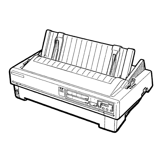
Two ways to insert single-sheet paper, using the front or top paper entrance Auto loading The LQ-870/1170 is equipped with the standard EPSON 8-bit parallel interface. The optional interface cards ensure compatibility with a wide variety of computers. Table l-l Lists the optional interface cards, Table 1-2 lists the optional units available for the LO-870/1170, and Figure l-l shows an exterior view of the LO-870/1170. -
Page 11: Figure 1-1. Exterior View Of The Lq-870 . . . . . . . . . . . . . . . . . . . . . . . . . . . . . . . . . . . . . . . . . . . . . . . . . . . . Figure 1-2. Pin Configuration
Fabric ribbon cartridge 7754 7 7 7 0 Film ribbon cartridge *When the last digit in the part number above is represented by an asterisk (“), the number varies depending on the country. Figure 1-1. Exterior View of the LQ-870... -
Page 12: Specifications
REV.-A 1.2 SPECIFICATIONS This section provides the specifications for the LQ-870/1170. 1.2.1 Hardware Specifications Serial, impact, dot matrix Printing method 24 wires; 12 x 2 staggered, diameter 0.2 mm (.008 in.) Pin configuration Figure 1-2. Pin Configuration Feeding methods Friction feeding (front and top paper entrances) -
Page 13: Table 1-3. Specifications For Single-Sheet Paper
REV.-A Friction feeding precautions Move the release lever to the FRICTION position. Load paper into the front or top paper entrance. Do not perform any reverse feeds within the top 8.5 mm (.34 in.) or bottom 22 mm (.87 in.) of the paper. -
Page 14: Table 1-6. Specifications For Envelopes
REV.-A Table 1-4. Specifications for Single-Sheet Multi-Part Forms (Carbonless) (80/l 36 column) Width 182 to 216/364 mm (7.2 to 8.5/l 4.3 in.) Length to 297 mm (10.7 to 11.7 in.) to 0.14 Thickness 0.065 mm (0.0025 to 0.0055 in.)- per sheet 0.12 to 0.64 mm (0.0047 to 0.0256 in.) total Weight 17 to 24 lb (52.3 to 90 g/mZ) single sheets... -
Page 15: Figure 1-3 Printable Area For Single-Sheet Paper
REV.-A See Figures 1-3, 1-4, and 1-5. Printable area top Insertion front lnsertlon 182-257 mm (7 Z-10.1”) ” 1 ) 3.0 mm (0.12 in.) or more when paper width is less than 229 mm (9 in.). 25 mm (0.9 in.) or more for top insertion or 26 mm (1 .O in.) or more for front insertion when paper width is 257 mm (10.1 in.). - Page 16 REV.-A Ink ribbon Black ribbon cartridge #7753 Film ribbon cartridge #7768 Black ribbon cartridge #7754 Film ribbon cartridge #7770 Color Black Life 2 million characters at 48 dots/character (black ribbon) 0.2 million characters at 48 dots/character (film ribbon), 80-column 0.3 million characters at 48 dots/character (film ribbon), 136-column Dimensions of ribbon cartridge: 80-column: 293 mm (width) x 34 mm (height) x 72 mm (depth)
- Page 17 REV.-A 1000 VAC rms for one minute or Dielectric strength 1200 VAC rms for one second (between AC line and chassis) 220 to 240 VAC Rated voltage 220 to 240 V version 198 to 264 VAC Input voltage range 50 to 60 Hz Rated frequency range 49.5 to 60.5 Hz Input frequency range...
-
Page 18: Firmware Specifications
10/9/91 1.2.2 Firmware Specifications ESC/P level ESC/P 2 Control codes (EPSON standard code for printers) Bidirectional with logic seeking Printing direction 8KB, 32KB, 84KB; to change RAM (4A 5A) Input data buffer Character code 8 bits Character tables Italic character table, PC 437, PC 850, PC 880, PC 883, PC 865 (PC indicates character tables for personal computers.) -
Page 19: Table 1-8. Printing (Text Mode)
1 o/9/9 1 NOTES: High-speed draft is valid when the printer’s status is as follows: . Condensed mode is not selected. . No D/L (download) characters are sent to the printer. . No bit image is sent to the printer. (The printer switches back to normal mode to print emphasized, condensed, or download characters and bit images.) See Tables l-8 and l-9. -
Page 20: Table 1-9. Printing (Bit Image Mode)
REV.-A Table 1-9. Printing (Bit Image Mode) 80/136-Column dpi: dots per inch ips: inches per second 1-11... -
Page 21: Table 1-10. Character Matrix And Character Size
REV.-A Table 1-10. Character Matrix and Character Size LQ, 12 pitch, condensed 3 6 0 LQ, proportional Max. 37 X 22 3 6 0 2.6 X 3.1 Min. 18 X 22 3 6 0 1.0 x 3.1 3 6 0 3 6 0 LQ, proportional, super/subscript Max. -
Page 22: Figure 1-5. Character Matrix
REV.-A (Typical LO character) (Typical draft character} area Ascender area Ascender Descender area Descender area 29 dots (Typical LQ. excluding 15 pitch) 15 dots for Character width (CW) 15 pitch and condensed LO Character width (CW) 1 2 dots (10 CPI) 120 DPI 15 dots (12 CPI) 180 DPI 1 6 dots (15 CPI) 240 DPI 3 6 dots (10 CPI) 360 DPI... -
Page 23: Figure 1-6. Data Transmission Timing
REV.-A 1.3 PARALLEL INTERFACE The specifications for the printer’s 8-bit parallel interface are as follows: Data format 8-bit parallel /STROBE signal Synchronization BUSY and / ACKNLG signal Handshaking TTL-compatible Signal level 57-30360 (Amphenol) or equivalent Adaptable connector See Figure 1-6. Data transmission timing BUSY ACKNLG... -
Page 24: Table 1-11. Connector Pin Assignments And Signal Functions
1 o/9/91 Table 1-11. Connector Pin Assignments and Signal Functions (Cont.) Signal Name Return Dir. Function Pin No. If LOW when the printer is initialized, the printer automatically /AUTOFEED-XT performs a line feed upon input of the CR code (auto LF). Not used. -
Page 25: Figure 1-7. Control Panel
1 o/9/91 1.4 CONTROL PANEL There are seven non-lock buttons and 19 indicators on the control panel. D R A F T R o m a n Figure 1-7. Control Panel 1.4.1 Buttons (1) Operate switch Use this switch to turn on the power supply to the printer. (2) PAUSE button Press this button to toggle the printer between the PAUSE condition (in which there is no printing or paper feeding and the printer does not accept data) and the RUNNING condition. -
Page 26: Indicator Lights
REV.-A 1.4.2 Indicator Lights (1) OPERATING (green) Lit when the printer’s operate switch is on and AC power is supplied. (2) PAUSE (orange) Lit when the printer is in PAUSE mode. In PAUSE mode, there is no printing or paper feeding and the printer does not accept data. -
Page 27: Table 1-12. Dip Switch Set 1 (Sw1)
REV.-A 1.5 DIP SWITCHES AND JUMPERS DIP switches and jumpers of the LQ-870/1170. This section describes the 1.5.1 DIP Switches The printer has two banks of DIP switches located on the control panel. Tables 1-12 through 1-15 describe the functions of the DIP switches. The status of the DIP switches is read only at power-on or upon receipt of the ANIT signal. -
Page 28: Table 1-14. International And Pc Character Set Selection
REV.-A Table 1-14. International and PC Character Set Selection Country l - 3 l - l U.S. France 8 5 0 Germany 8 6 0 U.K. 8 6 3 Denmark 1 Sweden Italy Spain 1 When you turn on DIP switch l-4 and use ESC + 0 to select the italic character table, the country setting becomes U.S. -
Page 29: Figure 1-8. Self-Test
REV.-A 1.6 OPERATING INSTRUCTIONS This section describes the self-test, hexadecimal dump function, error states, printer initialization, and buzzer operation. 1.6.1 Self-Test To run the self-test in draft mode, turn on the printer while pressing the LOAD/EJECT button. To run the self-test in LQ mode, turn on the printer while pressing the LINE FEED/FORM FEED button. You can press the PAUSE button to stop or start the self test. -
Page 30: Paper-Out Detection And Form Override Function
REV.-A 1.6.3 Paper-Out Detection and Form Override Function The paper-out detector is attached to the printer mechanism. When the paper-out detector senses a paper end, the printer first performs a form override. If paper loading fails, the BUSY signal goes HIGH, the PAPER OUT indicator light comes on, the interface PE signal becomes HIGH, the /ERROR signal becomes LOW, and the printer enters the PAUSE condition. -
Page 31: Printer Initialization
REV.-A 1.6.6 Printer Initialization There are three types of initialization: hardware, software, and control panel. (1) Hardware initialization This type of initialization takes place when you turn on the printer (and the AC power cord is plugged in) or when the /INIT signal is received. When the printer is initialized, it performs the following actions: (a) Initializes the printer mechanism. -
Page 32: Paper Loading And Ejection
REV.-A 1.6.8 Paper Loading and Ejection The release lever can disengage the pull tractor drive mechanism. This provides the printer with the following paper handling features: Automatic single-sheet loading without the cut-sheet feeder Move the release lever to the friction feed position and place the sheet along the top or front paper guide. -
Page 33: Figure 1-10. Paper-Thickness Lever Positions
REV.-A Short tear off To use the short tear-off function, press the TEAR OFF button. The release lever must be in the tractor position. The paper advances to the tear-off position, whether the printer is in the PAUSE or the RUNNING condition. - Page 34 REV.-A 1.6.11 Protection during Heavy Duty Printing This printer has a protection function to prevent the printhead from overheating and to stop printing when the head driver voltage drops. If the temperature of the printhead exceeds the maximum allowed value, printing stops automatically. When the printhead temperature drops to a certain value, printing resumes.
-
Page 35: Figure 1-11. Lq-870/1170 Component Layout
CO60 MAIN Main board in original LQ-870s and LQ-1170s. A different board CO60 board was used for the LQ-870 and for the LQ-1170. Driver circuitry was on a separate board. Contained driver circuitry. Used only with the CO60 MAIN board. -
Page 36: Figure 1-12. C060 Main, C061 Main, And C060 Main B Boards
The CO60 MAIN board was the original board used in the LQ-870/1170 printer when it was released in 1991. (There were separate CO60 MAIN boards for the LQ-870 and LQ-1170, and it required a driver board.) The CO61 board for the LQ-1170, which became available in 1992, combined the main board with the driver circuitry. -
Page 37: C060 Pnl Board (Control Panel Circuit Board)
1.7.2 C060 PNL Board (Control Panel Circuit Board) The CO60 PNL board the LQ-870/1170 control panel, which includes the buttons, indicator LEDs, and DIP switches. Figure 1-13. CO60 PNL Board 1.7.3 C060 PSB Board (Power Supply Circuit Board) The power supply unit consists of a switching regulator circuit that converts the AC line voltage to the DC vottages (for example, +35 V and +5 V) used by the printer. -
Page 38: Figure 1-16. M-5D10/5D60 Printer Mechanism
Figure l-15. CO60 DRV Board 1.7.5 M-5D10/5D60 Printer Mechanism The M-5D10/5D60 printer mechanism was developed specifically for use with LQ-870/1170. Its components include the carriage motor, carriage mechanism, paper-feed motor, paper-feed mechanism, ribbon-feed mechanism, printhead, and sensors. The printer mechanism provides four ways to insert paper. -
Page 39: Housing
1.7.5 Housing The LQ-87011170 housing consists of the upper, lower, and front cases. The front case houses the control panel board. The lower case contains the printer mechanism, main control circuit board, power supply circuit board. (LQ-870) Figure l-17. Housing 1-30... -
Page 40: Operation Principles
REV.-A CHAPTER 2 OPERATION PRINCIPLES PRINTER MECHANISM OPERATION ..........2-1 Printhead Mechanism ............2-1 2.1.1 2.1.2 Carriage Movement Mechanism ........2-2 Paper Advance Mechanism ..........2-3 2.1.3 2.1.3.1 Paper Feeding Mechanisms ........2-4 2.1.3.2 Paper Insertion Entrances ......... 2-6 Ribbon Advance Mechanism ..........2-11 2.1.4 2.2 POWER SUPPLY OPERATION ............ - Page 41 REV.-A Figure 2-13. Friction Feeding Using the Front Entrance ....2-9 Figure 2-14. Pull Tractor Feeding Using the Front Entrance ..2-9 Figure 2-14-1.
-
Page 42: Printer Mechanism Operation
REV.-A 2.1 PRINTER MECHANISM OPERATION This section describes the Model 5D lo/5060 printer mechanism and explains how it works. The Model 5D 1 O/5060 printer mechanism features a 24-pin impact dot printhead for serial printing. The printer mechanism has four main parts: the printhead mechanism, the carriage movement mechanism, the paper advance mechanism, and the ribbon advance mechanism. -
Page 43: Carriage Movement Mechanism
REV.-A 2.1.2 Carriage Movement Mechanism A timing belt is connected to the carriage on its lower side. With the printhead installed, this carriage moves in either direction along the carriage guide shaft. The carriage is driven by the carriage motor, a stepping motor that drives the timing belt via the belt drive pulley. -
Page 44: Paper Advance Mechanism
REV.-A 2.1.3 Paper Advance Mechanism The printer uses friction feeding to advance single-sheet paper and tractor feeding to advance continuous paper. There are three ways to advance paper using a tractor feed mechanism: using the push tractor, using the pull tractor, or using the push and pull tractors together. During normal operation, the printer has one tractor that functions as either a push or a pull tractor, depending on where it is attached to the printer. - Page 45 REV.-A Push Tractor Method When the push tractor is selected, the tractor reduction gear engages the tractor gear on the tractor assembly. The tractor reduction gear is driven by the paper-feed gear, which in turn is driven by the paper-feed motor pinion gear. The paper-feed pinion gear, when turning in the direction of the black arrow, results in pushing the paper through the mechanism.
- Page 46 REV.-A Pull Tractor Method Pull tractor feeding is basically the same as push tractor feeding. In push tractor feeding, the tractor (the paper advance inechanism) is before the paper entrance. It pushes the paper through the printer mechanism. In pull tractor feeding, however, the tractor is after the paper entrance. Because it pulls the paper through the printer mechanism, it requires no paper tension unit.
-
Page 47: Paper Insertion Entrances
REV.-A You use the release lever to switch between friction and tractor feeding. Setting the release lever to the friction feed position presses the paper advance roller against the platen. Setting the release lever to the tractor feed position separates the paper advance roller from the platen and releases this pressure. The release detector senses the current position of the release lever. - Page 48 REV.-A Rear paper insertion entrance When you insert paper into the rear entrance, the printer can use the push tractor, the pull tractor, or the push-pull tractor method to advance the paper. The rear paper-out detector senses when the paper runs out.
- Page 49 1 o/9/9 1 Paper (Continuous) Pull Tractor Printhead \ Paper Fekd Roller Figure 2-1 l-l. Push-Pull Tractor Feeding Using the Rear Entrance Bottom paper insertion entrance When you insert paper into the bottom entrance, the pull tractor advances the paper. The front paper-out detector senses when the paper runs out.
- Page 50 REV.-A Front paper insertion entrance When you insert paper into the front entrance, the printer can use friction feeding, the push tractor, the pull tractor, or the push and pull tractors to advance the paper. The front paper-out detector senses when the paper runs out.
- Page 51 REV.-A Paper (Cut sheet) From Front Insertion Paper-End Sensor Push Tractor Figure 2-14-l .Push Tractor Feeding Using the Front Entrance Paper (Continuous) From Front lnserti Paper-End Sensor Figure 2-14-2. Push Pull Tractor Feeding Using the Front Entrance 2-10...
-
Page 52: Ribbon Advance Mechanism
REV.-A 2.1.4 Ribbon Advance Mechanism The ribbon drive gear advances the ribbon through a gear linkage. This arrangement of gears always turns the ribbon drive gear counterclockwise, regardless of the direction in which the carriage is moving. Table 2-2. Ribbon Advance Gear Linkage Direction Carriage Gear Linkage... -
Page 53: Power Supply Operation
REV.-A 2.2 POWER SUPPLY OPERATION The printer can be powered by either of two power supply boards: the 120 V CO60 PSB board or the ways in which they supply power to the printer are identical. These power supply boards output the DC current necessary to drive the printer control circuits and the printer drive mechanism. -
Page 54: Power Supply Board
REV.-A The +35 VDC line has a voltage overload protection circuit and a voltage drop protection circuit. The It stops switching circuit operation, which stops the output of the +35 VDC line. The voltage drop protection circuit protects the printer from damage that might occur if the secondary circuitry of the stops the output of the +35 VDC line. -
Page 55: Control Circuit Operation
2.3 CONTROL CIRCUIT OPERATION The control circuit consists of three boards: the main board (CO60 MAIN, CO61 MAIN, or CO69 MAIN B), which is the main control board, the CO60 DRV board, the driver board (used only with the CO60 MAIN board), and the CO60 PNL board, the control panel board. - Page 56 REV.-A Table 2-5 lists the functions of the printer’s main components and circuits. The CPU converts the print data sent from the host computer to image data (the print image). Then the printer loads the image data to RAM. The printer processes each line of data sequentially. The CPU transfers the print data to the printhead drive circuit and sends the printhead drive pulse to the printhead drive circuit.
- Page 57 REV.-A Table 2-5. Functions of the Main IC and Circuits Location Functions Receives data from the host computer and loads the data to the input buffer in RAM (under interrupt processing control). Expands the input data held in the buffer to create image data. Loads this image data to the image buffer in RAM. Transfers the image data to the printhead drive circuit.
-
Page 58: Reset Circuit
1 O/9/9 1 2.3.2 Reset Circuit Figure 2-19 shows the reset circuit in block diagram form. The reset circuit issues the /RESET signal. The control circuits are initialized when they receive the /RESET signal. The conditions under which the /RESET signal is output are described below. -
Page 59: Sensor Circuits
REV.-A CPU Self Reset Power On VCCON DISC THLD RESET Figure 2-20. /RESET Signal Timing 2.3.3 Sensor Circuits Figure 2-21 shows the sensor circuits in block diagram form. When the printhead temperature exceeds the maximum allowed value, the TEMP2 signal and other signals, such as the CRHOME signal, are sent directly to the CPU. -
Page 60: Carriage Motor Drive Circuit
REV.-A 2.3.4 Carriage Motor Drive Circuit Figure 2-22 shows the carriage motor drive circuit. An open-loop, constant-current drive arrangement runs the carriage motor. 2-2 and l-2 phase excitation drive the motor. 2-2 phase excitation corresponds to two l-2 phase excitation steps. For each single-step phase change of a 2-2 phase excitation motor, the carriage moves l/120 inch. -
Page 61: Paper Advance Motor Drive Circuit
1 o/9/9 1 2.3.5 Paper Advance Motor Drive Circuit The printer uses a stepping motor to advance the paper. The minimum amount the printer can advance paper is l/360 inch. The motor is a 2-2 or 1-2 phase, constant-voltage drive motor. P70 to P73 in the CPU are the control ports for the stepping motor. -
Page 62: Printhead Drive Circuit
REV.-A 2.3.6 Printhead Drive Circuit Figure 2-24 shows the printhead drive circuit in block diagram form. The print data already has been expanded to create the image data. The CPU splits up this data three times and transfers this information to the latch circuit in the E05A49. -
Page 63: Parallel Interface Circuit
REV.-A 2.3.7 Parallel Interface Circuit Figure 2-26 shows the parallel interface circuit in block diagram form. The /STROBE signal latches the data sent from the host computer in E05A49. E05A49 automatically outputs the BUSY signal to stop the host computer from sending more data. Then it outputs the/lBF signal for the CPU. The CPU receives the /IBF signal via the interrupt signal input port P82, recognizes that the printer has received the data from the host computer, and reads the data latched in the E05A49. - Page 64 1 o/w93 APTER 3 LY AND ASSEMBLY 3.1 OVERVIEW ............Disassembly Precautions .
- Page 65 10/18/93 Removing the Power Supply Board ........Figure 3-10.
- Page 66 REV.-A 3.1 OVERVIEW This section describes disassembly precautions, tools, service checks after repair, and screw specifications. 3.1.1 Disassembly Precautions Follow the precautions below when disassembling the printer. Before disassembling, assembling, or adjusting the printer, disconnect the power cord from the external AC power socket.
-
Page 67: Checks After Repair
REV.-A 3.1.3 Checks After Repair Service When repaired printer is to be sent back to the customer, use the checklist shown in Table 3-3 to note the current state of the components. This checklist provides a record to make servicing and shipping more efficient. - Page 68 1 o/9/9 1 3.1.4 Screw Specifications In the following sections, abbreviations are used for parts, such as screws and washers. Tables. 3-4 small and 3-5 list these abbreviations. Table 3-4. Abbreviations Used for Screws Abbreviation Part Name Cross-recessed Bind head Cone point S tight screw Cross-recessed Bind head Cone point B tight screw Cross-recessed Bind head screw CBS(O)
-
Page 69: Disassembly And Assembly
3.2 DISASSEMBLY AND ASSEMBLY This section describes how to disassemble and assemble the main components of the printer. When the procedure for installing a component in the printer is simply the reverse of the procedure for removing the component from the printer, no description of how to install the component is given. Assembly and adjustment notes follow the disassembly procedure description, when necessary. -
Page 70: Removing The Printhead
1 o/9/91 3.2.1 Removing the Printhead Remove the printer cover. Remove the paper eject cover. Figure 3-2. Removing the Printer and Paper Eject Cover Remove the 2 screws that secure the printhead to the carriage. Lift out the printhead. Disconnect the upper and lower FCCs from the printhead. Printhead Head Cable Figure 3-3. - Page 71 3.2.2 Removing the Printer Case This section describes how to remove the front case and upper case. 3.2.2.1 Removing the Front Case Remove the printer cover. Remove the CB (M3 X 8) screw securing the front case to the upper case. Release the clips that secure the front case to the upper case.
-
Page 72: Removing The Circuit Boards
CO60 DRV board and CO60 MAIN board. Section 3.2.3.3 describes how to remove the CO61 MAIN board (LQ-1170 only) or the CO60 MAIN B board (defined at the factory either for the LQ-870 or the LQ-1170). Section 3.2.3.4 describes removal of the CO60 PSB board, and Section 3.2.3.5 describes removal of the CO60 PNL board. - Page 73 3.2.3.2 Removing the Main Board (C060 MAIN Board) Remove the upper case, as described in Section 3.2.2.2. Remove the mechanism unit, as described in Section 3.2.4. Remove the driver board, as described in Section 3.2.3.1. Disconnect CN4 and CN6 from the main board. Remove the 3 CBB(C) (M3 X 12) screws and 2 CB (Ml X 8) screws that hold the main board to the lower case: then remove the main board.
- Page 74 3.2.3.3 Removing the Main Board (C061 MAIN or C060 MAIN B) Remove the upper case, as described in Section 3.2.2.2. Remove the mechanism unit, as described in Section 3.2.4. Remove 2 CBS M3 x 6 screws attaching the shield plate, and remove the shield plate. Disconnect the cables from connectors CN4 through CN16 on the main board.
- Page 75 C060 power supply board for replacement, To remove the you must use a special extractor tool, available from Epson Parts Order Services. After obtaining this special tool, follow the procedure below. fuming Tool Caver Figure 3-9. Special Extractor Tool Remove the upper case, as described in Section 3.2.2.2.
- Page 76 3.2.3.5 Removing the Control Panel Board (C060 PNL Board) Remove the front case, as described in Section 3.2.2.1. Remove the 5 CBS(C) (M3 X screws that secure the control panel board to the front case; then remove the control panel board. Front Case CO60 PNL Board Figure 3-11.
- Page 77 3.2.4 Removing the Printer Mechanism Remove the upper case, as described in Section 32.2.2. Remove the 2 CB (M3 X 6) screws that attach the frame to the right shield plate. Remove the shield plate. If your printer contains a separate main board and driver board, disconnect the 2 flexible flat cables following CO66 DRV board connectors: CN5 (white, P-pin);...
-
Page 78: Disassembling The Printer Mechanism
3.2.5 Disassembling the Printer Mechanism This section describes how to disassemble the main components of the printer mechanism. 3.2.5.1 Removing the Carriage Motor Remove the printer mechanism from the tower case, as described in Section 3.2.4. Remove the printer spring (778 gm) from the base frame. Remove the timing belt from the heft pulley. - Page 79 3.2.5.2 Removing the Paper Advance Motor Remove the printer mechanism from the lower case, as described in Section 3.2.4. Remove the 2 CBS (M8 X 10) that hoM the paper feed motor the right frame. advance Remove the paper motor from the right frame. Figure 3-14.
- Page 80 3.2.5.4 Removing the Carriage Remove the FFC, as described in Section 3.2.5.3. Remove the timing belt from the carriage. Remove the hexagon nut (M4) and gap adjustment lever. Use the box driver to rotate and free the adjust bushing. Remove the bushing. Remove the carriage guide shaft by pulling the carriage guide shaft a little to the right.
- Page 81 3.2.5.5 Removing the Platen Remove the printer mechanism from the lower case, as described in Section 3.2.4. Remove the 2 CBS (M3 X 8) screws that secure the platen cover to the left and right frames. Remove the platen cover. Set the gap adjustment lever to 6.
- Page 82 3.2.5.6 Removing and Disassembling the Right Frame Remove the printer mechanism from the lower case, as described in Section 3.2.4. Remove the platen from the printer mechanism, as described in Section 3.2.5.5. Remove the carriage motor from the base frame, as described in Section 3.2.5.1. Remove the 4 CBS(C) (M3 X 10) screws that secure the right frame to the base frame.
- Page 83 3.2.5.8 Removing and Disassembling the Paper Guide Support Assembly Remove the printer mechanism from the lower case, as described in Section 3.2.4. Remove the platen from the printer mechanism, as described in Section 3.2.5.5. Remove the right frame from the base frame, as described in Section 3.2.5.6. Remove the left frame from the bass frame, as described in Section 3.2.5.7.
- Page 84 Assembly Note Plain Washer Mark Side Figure 3-23. Insertion Direction for Plain Washer Paper Guide (Right Side) Release Shaft Figure 3-24. Inserting the Release Shaft 3-19...
- Page 85 6/4/93 3.2.5.10 Removing the Home-Position Sensor Remove the printer mechanism from the lower case, as described in Section 3.2.4. Remove the clips that secure the home-position sensor from the rear side of the base frame. Remove the home-position sensor from the rear of the base frame. Figure 3-25.
- Page 86 3.2.5.12 Removing the Front Paper-Out Detector Remove the printer mechanism from the lower case, as described in Section 3.2.4. Open the clips that hold the front paper-out detector to the base frame. Remove the front paper-out detector. Paper-Out Detector Figure 3-27. Removing the Front Paper-Out Detector 3.2.5.13 Removing the Platen-Gap Sensor Remove the printer mechanism from the lower case, as described in Section 3.2.4.
- Page 87 3.2.5.14 Removing the Release Sensor Remove the printer mechanism, as described in Section 3.2.4. Remove the platen from the printer mechanism, as described in Section 3.2.5.5 Remove the right frame, as described in Section 3.2.5.6. (Follow 1 through 4.) steps Unhook the release sensor from the paper guide.
- Page 88 1 o/w93 3.2.5.15 Disassembling the Tractor Unit Remove the tractor unit from the printer. Remove the cog (17 mm) from the tractor shaft. Remove the right tractor frame from the tractor shaft and the guide shaft; tractor Remove E-ring 6 from the tractor shaft. Remove the right tractor, the paper support unit, and the left tractor from the tractor shaft and tractor guide shaft.
- Page 89 10/9/91 CHAPTER 4 ADJUSTMENTS 4.1 ADJUSTING THE PRINTER MECHANISM ........4.1.1 Carriage Motor Backlash Adjustment .
-
Page 90: Adjusting The Printer Mechanism
1 o/9/9 1 4.1 ADJUSTING THE PRINTER MECHANISM This section describes the various adjustments you may need to make to the printer mechanism. 4.1.1 Carriage Motor Backlash Adjustment In the carnage motor backlash adjustment, the pinion gear of the carriage motor is meshed smoothly with the belt pulley cog. - Page 91 1 o/9/91 4.1.2 Platen Gap Adjustment The platen gap adjustment must be done if any of the following conditions exist: * The carriage guide shaft has be rotated or reassembled, * The adjustment bushing has been rotated, (To test, print 1-2 pages in LQ self-test with a new ribbon.) Remove the printer mechanism from the lower case (see Section 3.2.4).
- Page 92 Left Frame Figure 4-3. The Adjustment Bushing 11. Move the printhead to the middle of the carrier guide shaft and check the gap again. It should still be 0.38mm. If it is out of adjustment go to step 7, otherwise go to step 12. 12.
- Page 93 4.2 BIDIRECTIONAL PRINT POSITION ADJUSTMENT This section describes how to adjust the bidirectional print position to ensure correct printing alignment. 4.2.1 Overview of Bidirectional Print Position Adjustment This printer prints characters when the carriage is moving in either direction (i.e., from left to right or from right to left). Adjustment is necessary to ensure that the printing of characters in one direction is properly aligned with the printing of characters in the opposite direction.
- Page 94 Are the characters aligned vertically? NO -> GO TO STEP 3. YES -> GO TO STEP 4. Refer to the odd-numbered lines (1st and 3rd), and adjust the even-numbered lines (2nd and 4th). Press the LOAD/EJECT button once while pressing the ALT button. (The reference value increases +l and even lines shift to the left.) Press the LF/FF button once while pressing the ALT button.
-
Page 95: Troubleshooting
REV.-A CHAPTER 5 TROUBLESHOOTING 5.1 OVERVIEW ....................5-1 5.2 REPAIR BY UNIT REPLACEMENT............ 5-2 5.3 REPAIR OF THE POWER SUPPLY BOARD........5-14 5.4 REPAIR OF THE M A I N BOARD............5-16 5.5 REPAIR OF THE PRINTER MECHANISM........5-19 LIST OF FIGURES Figure 5-1. - Page 96 2 = CR-A, pin 3 = CRB, pin 4 = CR-B, pin 5 = common) Paper-feed motor Shinano Kenshi motor: Coil resistance - 56.0 f 4 ohms at 77” F (25’ C) Seiko Epson motor: Coil resistance -5l.Of4ohmsat77”F(25”C) 4 = PF-B, pin 5 = common) (pin...
-
Page 97: Repair By Unit Replacement
REV.-A 5.2 REPAIR BY UNIT REPLACEMENT For most problems, level. Refer to Table it is sufficient for you to determine the difficulty to the unit 5-3, identify what the problem is, then perform the checks according to the corresponding flowchart. Table 5-3. - Page 98 1 o/9/91 (1) Printer Fails to Operate when Power is On START R e p l a c e t h e M e a s u r e t h e r e s i s t a n c e o f t h e c a r r i a g e m o t o r , PF motor and pr i nthead...
- Page 99 1 o/9/9 1 (2) Carriage Operation is Abnormal START m e c h a n i s m i n s e r t e d p r o p e r l y i n t o c o n n e c t o r s home position? S e e S e c t i o n...
- Page 100 (3) Printing is Faulty During Self-Test, but Carriage Operation is Normal START do necessary adjustments. S e e C h . 4 f o r V e r i f y t h e c o n t i n u i t y o f C N 4 t h e y a r e s e c u r e l y connected.
- Page 101 R e p l a c e pluggable chips on main board...
- Page 102 Wire Assignments) C o i l Reslrtanco- 1 6 . 7 k 1 . 7 o h m s (at 770 F , 280 C) between the coil (14, 22, 19, 23)
- Page 103 1 6 . 7 f 1 . 7 Coil Resistance: Thermistor Resistance: 9.4 f 0.94K ohms Rear Connector Test Point 1 I Test Point 2 3, 7, 11, 15 14, 22, 19, 23 2, 6, 10, 18 Front Connector Test Point 1 Test Point 2 5, 9, 13, 17 4, 12, 20, 21...
- Page 104 REV.-A (4) Paper Feeding is Abnormal (but Printing is Normal) L o a d t h e p a p e r c o r r e c t l y . L o a d t h e p a p e r c o r r e c t l y . Refer to section 5.5, Refer to section 5.5, Repair of the printer...
- Page 105 REV.-A m a i n l o g i c b o a r d . NOTE C h e c k m o t o r r e s i s t a n c e . P e r f o r m f i n a l t e s t .
- Page 106 REV.-A Check left and r i g h t t r a c t o r s f o r p r o p e r p h a s i n g . A d j u s t p h a s i n g o r r e p l a c e s p r o c k e t a s s e m r y .
- Page 107 REV.-A (5) Control Panel Operation is Abnormal f a u l t c o r r e c t e d ? Replace the control panel R e p l a c e t h e m a i n b o a r d . b o a r d .
- Page 108 REV.-A (6) Printing of Data Sent by the Host Computer is Faulty NOTE: It is assumed here that the host computer is operating normally. Refer to other troubleshooting Replace the connection cable f r o m t h e h o s t c o m p u t e r . f a u l t c o r r e c t e d ? R e p l a c e t h e m a i n b o a r d .
- Page 109 REV.-A 5.3 REPAIR OF THE POWER SUPPLY BOARD This section describes problems that indicate that the power supply board is defective, and it provides various symptoms, likely causes, and checkpoints. Checkpoints refer to power waveforms, resistance values, and other values to be checked to evaluate the operation of any component that might be bad. Check these values and take the appropriate action.
- Page 110 Table 5-4. Repair of the Power Supply Board (Continued) 5-15...
- Page 111 REV.-A 5.4 REPAIR OF THE MAIN/DRIVE BOARD This section provides instructions for repairing the main board when it is defective and describes various symptoms, likely causes, and checkpoints. Checkpoints refer to proper waveforms, resistance values, and other values to be checked to evaluate the operation of any component that might be @ad. Check these values and take the appropriate action.
- Page 112 REV.-A Table 5-5. Repair of in the Main/Drive Circuit Board (Continued) Problem Symptom Cause Checkpoint Solution The printer The CPU does Either ROM or Replace IC3A not operate. RAM is does not op- or IC4A. erate at all. defective. The CPU is Check the oscillator signal at either pin 33 If a signal is defective.
- Page 113 REV.-A Table 5-5. Repair of in the Main/Drive Circuit Board (Continued.) Checkpoint Solution Cause Problem Symptom Measure the voltage at Vref (pin 1) of Self-test print- Self-test is The CPU can’t ing is not executed. measure the abnormal. voltage on the +35V line.
-
Page 114: Repair Of The Printer Mechanism
REV.-A 5.5 REPAIR OF THE PRINTER MECHANISM 3, Disassembly and Assembly, for detailed procedures for replacing or adjusting parts, refer to Chapter 4, Adjustment. and Chapter If a problem or symptom recurs following an attempted repair, refer to Table to try to find other potential causes. Table 5-6. -
Page 115: Adjustments
The paper-feed motor Measure the coil Replace the paper- feed motor. is defective. resistance for the paper-feed motor. The approximate value should be 56 ohms (for the Shinano Kenshi motor) or 51 ohms (for the Seiko Epson motor). 5-20... - Page 116 REV.-A Table 5-6. Repair of Printer Mechanism (Continued) Checkpoint Problem Symptom Cause Solution The ribbon is not The ribbon feed is The ribbon car- Dismount the rib- Replace the ribbon abnormal. fed. tridge is defective. bon cartridge, ro- cartridge. tate its knob manu- ally, and check whether the ribbon feeds normally.
-
Page 117: Maintenance
6.2 LUBRICATION A N D ADHESIVE APPLICATION......6-1 LIST OF FIGURES Figure 6-1. Correct Adhesive Application ..........6-2 Figure 6-2. LQ-870 Lubrication Points............6-3 Figure 6-3. LQ-1 1 7 0 Lubrication Points ............. 6-4 LIST OF TABLES Table 6-1. Lubricants and Adhesive ............6-1 Table 6-2. -
Page 119: Preventive Maintenance
6.2 LUBRICATION AND ADHESIVE APPLICATION EPSON recommends that the printer be lubricated at the points illustrated in Figure 6-2. Table 6-2 lists each point together with its recommended lubricant. The three recommended lubricants are EPSON O-2, G-20, and G-26, all of which have been tested extensively and found to comply with the needs of this printer. - Page 120 REV.-A Table 6-2. Lubrication Points (Refer to Figure 6-2) Lubricant Ref. No. Lubrication Points G-26 G-26 G-26 G-26 Portion of carriage that contacts base frame Oil pad G-26 Gear (40 mm) shaft G-26 Gear (40 mm) shaft G-26 Portion of paper guide that contacts sub paper guide G-26 Portion of paper tension roller shaft that contacts paper tension frame Portion of tractor shaft that contacts tractor frame (left)
- Page 121 REV.-A Figure 6-2. LQ-870 Lubrication Points...
- Page 122 REV.-A Figure 6-3. LQ-1170 Lubrication Points...
- Page 123 APPENDIX A.1 CONNECTOR S U M M A R Y ..............A.2 CIRCUIT DIAGRAMS ................A-9 A.3 CIRCUIT BOARD COMPONENT LAYOUT........A-15 A.4 EXPLODED DIAGRAM................. A-20 A.5 CASE OUTLINE DRAWING..............A-25 LIST OF FIGURES Figure A-1. Cable Connections..............A-1 Figure A-2.
- Page 124 Table A-8. CN1 (CO60 DRV only) ..... . . A-7 Table A-9. CN2 (CO60 DRV) and CN7(CO61 MAIN and CO60 MAIN B) ....Table A-10.
- Page 125 A.1 CONNECTOR SUMMARY Figure A-l illustrates the interconnection of major components. Table A-l summarizes the functions and sizes of the connectors. A C I N P U T POWER ( S P I N ) P S B B o a r d R E L E A S E L E V E R CR MOTOR...
- Page 126 ................
- Page 127 Table A-1. Board Connector Summary No. of Pins Function Board CN No. Parallel interface CO61 MAIN and Optional interface CO60 MAIN B board Optional font cartridge (include driver Control panel board functions) Printhead R side Printhead L side Power supply (+35 V) Power supply (+5 V) Fan motor Carriage motor...
- Page 128 Table A-3. CN2 (CO60, CO61, and CO60 MAIN B) Table A-2. CN1 (CO60, C061, and CO60 MAIN B) No. ~ I/O i Signal Name No. I I/O ’ Signal Name STROBE DATA 1 DATA3 - 5 v DATA4 DATA5 DATA6 DATA7 READY DATA8...
- Page 129 Table A-4. CN3 (CO60, CO81, and CO80 MAIN B) No. ) I/O 1 Signal Name - C N T PROGA 15 PROGA 14 - R A M CGA22 - C G CGA18 PROGA 13 CGA13 RAM14 Al 1 CGA16 RAM16 A l 2 CGA17 Table A-5.
- Page 130 Table A-6. CN5 (CO60 MAIN only) No. I I/O I Signal Name No. ( I/O / Signal Name I El: , -A -PFA CR HOME Table A-7. CN6 (CO60 MAIN) and CN4 (CO61 MAIN and CO60 MAIN B) PF COM -HOLD PAUSE LDLED...
- Page 131 Table A-8. CNl (CO60 DRV only) Signal Name -PFA CR HOME Table A-9. CN2 (CO60 DRV) and CN7 (CO61 MAIN and CO60 MAIN B) Signal Name PF COM -HOLD -PFB PE3 N.C...
- Page 132 Table A-13. CN6 (CO60 DRV) and Table A-10. CN3 (CO60 DRV) and Signal Name Signal Name H I 1 CR-A CR-B CRCOM Table A-14. CN7 (CO80 DRV) and Signal Name PF-B PFCOM Table A-l 1. CN4 (CO50 DRV) and CN6 (CO61 MAIN and CO60 MAIN B) Table A-15.
- Page 133 Table A-l 8. CNl 1 (CO80 DRV) and CN15 (CO81 MAIN and CO50 MAIN B) Tabb A-21. CN2 (CO60 PSB Board) Signal Name N o . Signal Name Table A-19. CN12 (CO80 DRV) and CN18 (CO81 MAIN and CO80 MAIN B) Signal Name Table A-20.
- Page 139 REV.-A A-3. CIRCUIT BOARD COMPONENT LAYOUT . . . - - - Figure A-7. CO60 MAIN Board Component Layout A - 1 5...
- Page 140 REV.-A Cl I CO60 DRV A S S Y . 2 0 0 3 0 7 2 01 Figure A-8. C060 DRV Board Component Layout A - 1 6...
- Page 147 “ 5 2 5 5 9 0...
- Page 148 REV.-A Table A-23-l. Part No. Reference Table for LQ-870 Table A-23-2. Part No. Reference Table for LQ-1170 Description Ref. No. Description Ref. No. HOUSING ASSY., LOWER HOUSING ASSY., LOWER FOOT FOOT HOUSING ASSY., UPPER HOUSING, FRONT HOUSING, FRONT HOUSING, FRONT COVER ASSY., PRINTER...
- Page 149 REV.-A A.5 CASE OUTLINE DRAWING Figure A-l 4-1. Case Outline Drawing for LQ-870 A-25...
- Page 150 REV.-A Figure A-l 4-2. Case Outline Drawing for LQ-1170 A - 2 6...
- Page 151 C O 6 1 M A I N B o a r d A - 3 7...
Need help?
Do you have a question about the LQ-870 and is the answer not in the manual?
Questions and answers