Fluke 190-104 Service Manual
Scopemeter 190 series ii
Hide thumbs
Also See for 190-104:
- Datasheet (10 pages) ,
- Technical data manual (9 pages) ,
- User manual (278 pages)
Table of Contents

Related Manuals for Fluke 190-104


Summary of Contents for Fluke 190-104
-
Page 1: Service Manual
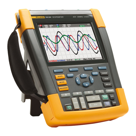
Fluke 190-104/190-204 ScopeMeter 190 Series II Service Manual PN 4822 872 05405 March 2011 © 2011 Fluke Corporation, All rights reserved. Printed in the Netherlands All product names are trademarks of their respective companies. - Page 2 PLACING ORDERS AND GETTING ASSISTANCE To locate an authorized service center, visit us on the World Wide Web: http://www.fluke.com or call Fluke using any of the phone numbers listed below: +1-888-993-5853 in U.S.A. and Canada +31-40-2675200 in Europe +1-425-446-5500 from other countries...
-
Page 3: Table Of Contents
Table of Contents Chapter Title Page Safety Instructions................1-1 1.1 Introduction....................1-3 1.2 Safety Precautions..................1-3 1.3 Caution and Warning Statements..............1-3 1.4 Symbols ....................... 1-3 1.5 Impaired Safety.................... 1-4 1.6 General Safety Information................1-4 1.7 Safe Handling and Use of Li-ion battery pack..........1-4 Characteristics .................. - Page 4 Fluke 190-104/190-204 Service Manual 4.6.14 Input C AC Voltage Accuracy (HF) & Bandwidth Test ....4-26 4.6.15 Input D Trigger Sensitivity Test............4-27 4.6.16 Input D AC Voltage Accuracy (HF) & Bandwidth Test ....4-28 4.6.17 Video test using the Video Pattern Generator ........4-29 4.6.18 Video test using SC600 Scope Calibration Option ......
-
Page 5: Title
Chapter 1 Safety Instructions Title Page 1.1 Introduction....................1-3 1.2 Safety Precautions..................1-3 1.3 Caution and Warning Statements..............1-3 1.4 Symbols ....................... 1-3 1.5 Impaired Safety.................... 1-4 1.6 General Safety Information................1-4... -
Page 7: Introduction
Safety Instructions 1.1 Introduction 1.1 Introduction Read these pages carefully before beginning to install and use the Test Tool. The following paragraphs contain information, cautions and warnings which must be followed to ensure safe operation and to keep the Test Tool in a safe condition. Warning Servicing described in this manual is to be done only by qualified service personnel. -
Page 8: Impaired Safety
The Test Tool uses a rechargeable Li-ion battery pack. For instructions how to safely handle and use this battery pack refer to Paragraph “Safety Information” in the Users Manual of Fluke 190-104 / 190-204 (ScopeMeter 190 Series II). The Users Manual can be downloaded from Fluke’s website. -
Page 9: Characteristics
Characteristics The Fluke 190 Series II ScopeMeter Test Tools have following main characteristics: - 4 isolated and identical channels, Bandwidth 100 MHz (Model 190-104) or 200 MHz (Model 190-204), rated 1000 V CAT III, 600 V CAT IV. - 2.5 GS/s (200 MHz version) or 1.25 GS/s (200 MHz) total sampling speed available for the channels. -
Page 11: List Of Replaceable Parts
Chapter 3 List of Replaceable Parts Title Page 3.1 Introduction....................3-3 3.2 How to Obtain Parts..................3-3 3.3 Final Assembly Parts ...................3-4 3.5 Accessories ....................3-7... - Page 12 Fluke 190-104/190-204 Service Manual...
-
Page 13: Introduction
3.1 Introduction 3.1 Introduction This chapter contains an illustrated list of replaceable parts for the models Fluke 190- 104/190-204 ScopeMeter test tools. Parts are listed by assembly; alphabetized by item number or reference designator. Each assembly is accompanied by an illustration showing the location of each part and its item number or reference designator. -
Page 14: Final Assembly Parts
Can be fixed on Left or Right side Hang Strap 946769 Can be fixed op Top Side of Instrument Main PCA Module Only available for Fluke (authorized) 8-1 / 12,13, (tested) workshops. Requires dedicated tools 8-2, 8-3 / 8 to configure. - Page 15 List of Replaceable Parts 3.3 Final Assembly Parts Part or Kit Ordering Code Consists of Following Parts Figure/Item nr Faston pin battery (5x, X9104-9108) Cushion (Fits around Faston pin) Sealing piece USB/Probe (black) 8-3 / 10 Sealing piece DC power (black) 8-3 / 11 Keypad 3942805...
- Page 16 Fluke 190-104/190-204 Service Manual Figure 3-2 Figure 3-3 Note The test tool contains a Li-ion battery. Do not mix with the solid wastestream. Spent batteries should be disposed of by a Li-Ion qualified recycler or hazardous materials handler.
-
Page 17: Accessories
List of Replaceable Parts 3.5 Accessories 3.5 Accessories For a list with accessories refer to the “Maintaining the Test Tool” Chapter in the Fluke 190-104 / 190-204 (ScopeMeter 190 Series II) Users Manual. The Users Manual can be downloaded from Fluke’s website. - Page 18 Fluke 190-104/190-204 Service Manual...
-
Page 19: Performance Verification
Chapter 4 Performance Verification Title Page 4.1 Introduction....................4-2 4.2 Equipment Required For Verification ............4-2 4.3 General Instructions ..................4-2 4.4 Operating Instructions..................4-3 4.4.1 Resetting the Test Tool.................4-3 4.4.2 Navigating through menu’s ..............4-3 4.4.3 Creating Test Tool Setup1..............4-4 4.5 Display and Backlight Test................4-5 4.6 Scope Input A, B, C, D Tests...............4-6 4.6.1 Input A, B, C, D Vertical Accuracy Test..........4-6 4.6.2 Input A, B, C, D DC Voltage Accuracy Test ........4-8... -
Page 20: Introduction
Fluke 5500A Multi Product Calibrator, including SC300 or SC600 Oscilloscope Calibration Option. • 50Ω Coax Cables (4x): use Fluke PM9091 (1.5m, 3 pcs.) and PM9092 (0.5m, 3 pcs.). • Male BNC to Dual Female BNC adapter (1x), Fluke PM9093/001 •... -
Page 21: Operating Instructions
Performance Verification 4.4 Operating Instructions 4.4 Operating Instructions 4.4.1 Resetting the Test Tool Proceed as follows to reset the Test Tool: • Press to turn the Test Tool off. • Press and hold USER • Press and release to turn the Test Tool on. •... -
Page 22: Creating Test Tool Setup1
Fluke 190-104/190-204 Service Information 4.4.3 Creating Test Tool Setup1 Before starting the verification procedure you must define a standard Test Tool setup, called SETUP 1. During verification you will be asked to recall this setup. This defines the initial Test Tool setup for each verification. -
Page 23: Display And Backlight Test
Performance Verification 4.5 Display and Backlight Test 23. Using select SCREEN+SETUP 24. Press ENTER 25. Using select . Remember the name under which the settings are OK SAVE saved (for instance SCOPE 1). 26. Press ENTER to save the settings. HOLD 27. -
Page 24: Scope Input A, B, C, D Tests
Fluke 190-104/190-204 Service Information Observe the display closely, and verify that the display shows no abnormalities. Also verify that the contrast of the upper left and upper right square of the test pattern is equal. 10. Press The test pattern is removed; the Test Tool shows Contrast (CL 0110): 11. - Page 25 Performance Verification 4.6 Scope Input A, B, C, D Tests SAVE • Recall the created setup (e.g. SETUP 1, see section 4.4.3): press , select , press ENTER to recall the setup. RECALL SCREEN+SETUP 1 • Press , press , and select INPUT A OPTIONS...
-
Page 26: Input A, B, C, D Dc Voltage Accuracy Test
Note The vertical accuracy test can also be done with dc voltage. This method is advised for automatic verification using the Fluke Met/Cal Metrology Software. For each sensitivity range you must proceed as follows: 1. Apply a +3 divisions voltage, and adjust the voltage until the trace is at +3 divisions. - Page 27 CONNECT TO CHANNEL A, B, C, D IN PARALLEL 50 OHM TERMINATION NORMAL SCOPE PM9081 FLUKE 5500A CALIBRATOR Figure 4-4. Test Tool Inputs A, B, C, D to 5500A Normal Output 1. Select the following Test Tool setup: SAVE •...
- Page 28 Fluke 190-104/190-204 Service Information 8. Next check channel B, C or D in succession: Press TRIGGER and select B, C or D as trigger source with Press B, C or D to assign vertical ‘range’ and ‘move’ to channel B, C or D, Observe reading B, C or D.
- Page 29 Performance Verification 4.6 Scope Input A, B, C, D Tests 100 V/div +300 V +291 to +309 -300 V -291 to -309 4-11...
-
Page 30: Input A, B, C, D Ac Voltage Accuracy Test (Lf)
Fluke 190-104/190-204 Service Information 4.6.3 Input A, B, C, D AC Voltage Accuracy Test (LF) This procedure tests the Volts ac accuracy with dc coupled inputs up to 50 kHz. The high frequencies are tested in sections 4.6.10, 4.6.12, 4.6.14 and 4.6.16. -
Page 31: Input A, B, C, D Ac Coupled Lower Frequency Test
Performance Verification 4.6 Scope Input A, B, C, D Tests 9. Next check channel B, C or D in succession: Press TRIGGER and select B, C or D as trigger source with Press B, C or D to assign vertical ‘range’ and ‘move’ to channel B, C or D, Observe reading B, C or D. -
Page 32: Input A And B Peak Measurements Test
Fluke 190-104/190-204 Service Information • Press – and select with – and with READING ... READINGS the arrow keys: Reading 1, on A, V ac, Reading 2, on B, V ac, Reading 3, on C, V ac, Reading 4, on D, V ac. -
Page 33: Input A, B, C, D Frequency Measurement Accuracy Test
Performance Verification 4.6 Scope Input A, B, C, D Tests 1. Connect the Test Tool to the 5500A as for the previous test (see Figure 4-4). 2. Select the following Test Tool setup: SAVE • Recall the created setup (e.g. SETUP 1, see section 4.4.3): press , select , press to recall the setup . - Page 34 Fluke 190-104/190-204 Service Information PM9091 PM9093 PM9092 CONNECT TO CHANNEL A, B, C, D IN PARALLEL 50 OHM TERMINATION NORMAL SCOPE FLUKE 5500A CALIBRATOR Figure 4-5. 5500A Scope Output to Test Tool Input A, B, C, D 2. Select the following Test Tool setup: SAVE •...
-
Page 35: Input A&B Phase Measurements Test
Performance Verification 4.6 Scope Input A, B, C, D Tests 190-104 20 ns/div levsine 300 mVpp 100 MHz 99.3 to 100.7 190-204 20 ns/div levsine 300 mVpp 200 MHz 198.8 to 201.2 Note Duty Cycle and Pulse Width measurements are based on the same principles as Frequency measurements. -
Page 36: Time Base Test
Fluke 190-104/190-204 Service Information 200 ns/div levsine 1 MHz 300 mVpp -2 to +2 20 ns/div levsine 10 MHz 300 mVpp -3 to +3 4.6.8 Time Base Test Proceed as follows to test the time base accuracy: 1. Connect the Test Tool to the 5500A as shown in Figure 4-6. -
Page 37: Input A Trigger Sensitivity Test
Performance Verification 4.6 Scope Input A, B, C, D Tests MOVE • move the trace to adjust the trigger delay time to 800.0 μs Using 800.0 μs TIME • set the time base on 1 μs/div. Using 7. Set the 5500A to source a 0.8 ms time marker (MODE marker). MOVE 8. - Page 38 Fluke 190-104/190-204 Service Information 8. When you are finished, set the 5500A to Standby. Table 4-8. Input A Trigger Sensitivity Test Points 5500A SC... MODE levsin Model Time base Initial Input Voltage Frequency Trigger Amplitude 200 ns/div 100 mV pp 5 MHz 0.5 div...
-
Page 39: Input A Ac Voltage Accuracy (Hf) & Bandwidth Test
5500A SC... MODE levsine Model Voltage Frequency Reading A 2.545 Vpp 1 MHz 835 mV to 965 mV 2.545 Vpp 25 MHz 790 mV to 1.010 V 190-104 2.545 Vpp 100 MHz >630 mV 190-204 2.545 Vpp 200 MHz >630 mV 4-21... -
Page 40: Input B Trigger Sensitivity Test
Fluke 190-104/190-204 Service Information 4.6.11 Input B Trigger Sensitivity Test Proceed as follows to test the Input B trigger sensitivity: 1. Connect the Test Tool to the 5500A as shown in Figure 4-8. PM9091 PM9585 - 50 OHM USE 50 OHM... -
Page 41: Input B Ac Voltage Accuracy (Hf) & Bandwidth Test
Performance Verification 4.6 Scope Input A, B, C, D Tests 190-104 10 ns/div 400 mV pp 100 MHz 1 div 10 ns/div 800 mV pp 150 MHz 2 div 190-204 10 ns/div 400 mV pp 200 MHz 1 div 10 ns/div... -
Page 42: Input C Trigger Sensitivity Test
Fluke 190-104/190-204 Service Information 4.6.13 Input C Trigger Sensitivity Test Proceed as follows to test the Input C trigger sensitivity: 1. Connect the Test Tool to the 5500A as shown in Figure 4-9. PM9091 PM9585 - 50 OHM USE 50 OHM... -
Page 43: Input C Ac Voltage Accuracy (Hf) & Bandwidth Test
Performance Verification 4.6 Scope Input A, B, C, D Tests 190-104 10 ns/div 400 mV pp 100 MHz 1 div 10 ns/div 800 mV pp 150 MHz 2 div 190-204 10 ns/div 400 mV pp 200 MHz 1 div 10 ns/div... -
Page 44: Input D Trigger Sensitivity Test
Fluke 190-104/190-204 Service Information 4.6.15 Input D Trigger Sensitivity Test Proceed as follows to test the Input D trigger sensitivity: 1. Connect the Test Tool to the 5500A as shown in Figure 4-10. PM9091 PM9585 - 50 OHM USE 50 OHM... -
Page 45: Input D Ac Voltage Accuracy (Hf) & Bandwidth Test
Performance Verification 4.6 Scope Input A, B, C, D Tests 190-104 10 ns/div 400 mV pp 100 MHz 1 div 10 ns/div 800 mV pp 150 MHz 2 div 190-204 10 ns/div 400 mV pp 200 MHz 1 div 10 ns/div... -
Page 46: Video Test Using The Video Pattern Generator
Fluke 190-104/190-204 Service Information 4.6.17 Video test using the Video Pattern Generator You can skip this test if you do the test 4.6.17 Video test using the SC600 Scope Calibration option Only one of the systems NTSC, PAL, PALplus, or SECAM has to be verified. - Page 47 Figure 4-15. Trace for NTSC line 262 7. Apply the inverted TV Signal Generator signal to the Test Tool. Invert the signal by using a Banana Plug to BNC adapter (Fluke PM9081/001) and a Banana Jack to BNC adapter (Fluke PM9082/001), as shown in Figure 4-16.
-
Page 48: Video Test Using Sc600 Scope Calibration Option
Fluke 190-104/190-204 Service Information PM9075 4119-75 75 OHM USE 75 OHM TERMINATION USE 75 OHM COAX CABLE PM5418 PM9082 PM9081 Figure 4-16. Test Tool Input A to TV Signal Generator Inverted 8. Select the following Test Tool setup: • Press to open the Trigger Options menu. - Page 49 1. Connect the Test Tool to the calibrator as shown in Figure 4-19. PM9091 PM9585 - 50 OHM USE 50 OHM TERMINATION NORMAL SCOPE FLUKE 5500A CALIBRATOR Figure 4-19. Test Tool Input A to TV Signal Generator 2. Select the following Test Tool setup: • Reset the Test Tool • Press...
-
Page 50: Probe Calibration Generator Test
Fluke 190-104/190-204 Service Information ⇒ SECAM 310 (odd), for SECAM ⇒ NTSC 262 odd, for NTSC. 7. Observe the trace, and check to see if the Test Tool triggers on the negative pulse before the marker. 8. Select the following Test Tool setup: •... - Page 51 Performance Verification 4.7 Probe Calibration Generator Test rotating the centre part of the housing. For further information refer to the probe instruction sheet. When done, press to start the DC calibration that is performed automatically. The Probe Calibration is OK if all instructions displayed on screen are finished succesfully.
- Page 52 Fluke 190-104/190-204 Service Information 4-34...
-
Page 53: Calibration Adjustment
Chapter 5 Calibration Adjustment Title Page 5.1 General......................5-3 5.1.1 Introduction ..................5-3 5.1.2 Calibration number and date..............5-3 5.1.3 General Instructions................5-3 5.1.4 Equipment Required For Calibration ...........5-4 5.2 Calibration Procedure Steps.................5-4 5.3 Starting the Calibration ................5-4 5.4 Contrast Calibration Adjustment ..............5-6 5.5 Warming Up & Pre-Calibration..............5-7 5.6 Final Calibration ..................5-8 5.6.1 Warm Up Final and ADC Timing ............5-8 5.6.2 Input A LF-HF Gain................5-9... -
Page 55: General
5.1.1 Introduction The following information, provides the complete Calibration Adjustment procedure for the Fluke 190-104 (100 MHz) / 190-204 (200 MHz) ScopeMeter Test Tool (referred to as Test Tool). The Test Tool allows closed-case calibration using known reference sources. It measures the reference signals, calculates the correction factors, and stores the correction factors in RAM. -
Page 56: Equipment Required For Calibration
• Fluke 5500A Multi Product Calibrator, including SC300 or SC600 Oscilloscope Calibration Option. • 50Ω Coax Cables (4x): use Fluke PM9091 (1.5m, 3 pcs.) and PM9092 (0.5m, 3 pcs.). • 50Ω feed through termination (4x), Fluke PM9585. • Male BNC to Dual Female BNC adapter (3x), Fluke PM9093/001. - Page 57 Calibration Adjustment 5.3 Starting the Calibration 3. Select the calibration mode. The Calibration Adjustment Procedure uses built-in calibration setups, that can be accessed in the calibration mode. To enter the calibration mode proceed as follows: • Press and hold , press and release CLEAR , release USER...
-
Page 58: Contrast Calibration Adjustment
Fluke 190-104/190-204 Service Information start the calibration adjustment of the actual step CALIBRATE leave the calibration mode EXIT 5.4 Contrast Calibration Adjustment After entering the calibration mode the display shows: WarmingUp (CL 0200):IDLE (valid) Do not press now! If you did, turn the Test Tool off and on, and enter the calibration mode again. -
Page 59: Warming Up & Pre-Calibration
Calibration Adjustment 5.5 Warming Up & Pre-Calibration Figure 5-2. Display Test Pattern 5.5 Warming Up & Pre-Calibration The WarmingUp & Pre-Calibration state will be entered after entering the calibration mode (section 5.3), or after selecting the next step if you have done the Contrast Calibration step CL 120 (section 5.4). -
Page 60: Final Calibration
Fluke 190-104/190-204 Service Information 5.6 Final Calibration Before starting the final calibration you must have done the WarmingUp & PreCalibration (section 5.5)! The final calibration requires input conditions that will be described in each step. After starting a step, several steps that require the same input conditions will be done automatically. -
Page 61: Input A Lf-Hf Gain
USE 50 OHM TERMINATION NORMAL SCOPE FLUKE 5500A CALIBRATOR Figure 5-3. 5500A SCOPE Output to Test Tool Input A. 5.6.2 Input A LF-HF Gain Proceed as follows to do the Input A LF-HF Gain calibration: 1. Connect the Test Tool to the 5500A as shown in Figure 5-3. -
Page 62: Input B Lf-Hf Gain
Fluke 190-104/190-204 Service Information Table 5-1. Input A LF-HF Gain Calibration Points Cal step UUT input signal 5500A Setting CL 0654 0.5 Vpp square wave, 1 kHz SCOPE edge, 0.5 Vpp, 1 kHz CL 0400 0.5 Vpp square wave, 1 kHz SCOPE edge, 0.5 Vpp, 1 kHz... -
Page 63: Input C Lf-Hf Gain
PM9585 - 50 OHM USE 50 OHM TERMINATION NORMAL SCOPE FLUKE 5500A CALIBRATOR Figure 5-4. 5500A SCOPE Output to Test Tool Input B 5.6.4 Input C LF-HF Gain Proceed as follows to do the Input C LF-HF Gain calibration: 1. Press to select the first calibration step in Table 5-3. -
Page 64: Input D Lf-Hf Gain
Fluke 190-104/190-204 Service Information Table 5-3. Input C LF-HF Gain Calibration Points Cal step UUT input signal 5500A Setting CL 0656 0.5 Vpp square wave, 1 kHz SCOPE edge, 0.5 Vpp, 1 kHz CL 0470 0.5 Vpp square wave, 1 kHz SCOPE edge, 0.5 Vpp, 1 kHz... -
Page 65: Input Abcd Lf-Hf Gain
0.62 Vpp sine wave, 50 kHz SCOPE levsine, 0.62 Vpp, 50 kHz CL 0487 0.62 Vpp sine wave SCOPE levsine, 0.62 Vpp, Fluke 190-204: 221 MHz 221 MHz Fluke 190-104: 141 MHz 141 MHz PM9091 PM9585 - 50 OHM USE 50 OHM TERMINATION NORMAL... - Page 66 Fluke 190-104/190-204 Service Information PM9091 CONNECT TO CHANNEL A, B, C, D IN PARALLEL PM9093 PM9092 50 OHM TERMINATION NORMAL SCOPE FLUKE 5500A CALIBRATOR Figure 5-7. Test Tool Input ABCD to 5500A SCOPE Output 3. Set the 5500A to supply a 1 kHz square wave (SCOPE, MODE volt, SCOPE Z 1 MΩ), to the first calibration point in Table 5-5.
-
Page 67: Input Abcd Position
Calibration Adjustment 5.6 Final Calibration Table 5-5. Input ABCD Gain Calibration Points Cal step UUT input value (5500A SCOPE, MODE volt, SCOPE Z 1 MΩ, 1 kHz) CL 0660 300 mV CL 0604 500 mV CL 0637 none (5500 standby) CL 0504 500 mV CL 0624... - Page 68 Fluke 190-104/190-204 Service Information Proceed as follows to do the Input ABCD Volt Gain calibration. 1. Press to select the first calibration step in Table 5-6. 2. Connect the Test Tool to the 5500A as shown in Figure 5-8. PM9091...
-
Page 69: Input Abcd Zero
Calibration Adjustment 5.7 Save Calibration Data and Exit Table 5-6. Input ABCD Gain Calibration Points Cal step UUT input value (5500A NORMAL) CL 0799 5 mV CL 0800 12.5 mV CL 0801 25 mV CL 0802 50 mV CL 0803 125 mV CL 804 250 mV... - Page 70 Fluke 190-104/190-204 Service Information Calibration data valid. Save data and exit maintenance mode? Note Calibration data valid indicates that the calibration adjustment procedure is performed correctly. It does not necessarily mean that the Test Tool meets the characteristics listed in Chapter 2.
-
Page 71: Probe Calibration
Calibration Adjustment 5.8 Probe Calibration 5.8 Probe Calibration To meet full user specifications, you need to adjust the supplied red (R), blue (B), gray (G) and green (V) VPS410 10:1 voltage probes for optimal response. To adjust the VPS410 probes, do the following: 1. - Page 72 Fluke 190-104/190-204 Service Information 5-20...
-
Page 73: Disassembling The Test Tool
Chapter 6 Disassembling the Test Tool Title Page 6.1. Introduction....................6-3 6.2. Disassembly & Reassembly Procedures .............6-3 6.2.1 Required Tools ..................6-3 6.2.2 Removing the Tilt Stand, Hang Strap, and Side Strap ......6-3 6.2.3 Opening the Test Tool, Removing the Battery Pack ......6-4 6.2.4 Getting access to Top Side of PCA ............6-4 6.2.5 Getting access to Bottom Side of PCA..........6-5 6.2.6 Getting access to LCD, Keypad Foil and Keypad........6-5... -
Page 75: Introduction
The Test Tool contains static sensitive components. Handling and servicing these components should be done only at a static free workstation by qualified personnel. The Test Tool contains a Li-ion battery pack. Refer to the Fluke 190-104/190-204 (Fluke 190 Series II) Users Manual “Safety Information” Chapter (page 4 onwards) for instructions how to safely handle and use this battery pack. -
Page 76: Opening The Test Tool, Removing The Battery Pack
Fluke 190-104/190-204 Service Manual 6.2.3 Opening the Test Tool, Removing the Battery Pack Proceed as follows: 1. Remove the battery access door with a standard blade screwdriver by turning the plastic battery door screws one-quarter turn counterclockwise. 2. Take the battery out of the instrument. -
Page 77: Getting Access To Bottom Side Of Pca
Disassembling the Test Tool 6.2. Disassembly & Reassembly Procedures 6.2.5 Getting access to Bottom Side of PCA Important: to avoid contaminating the flex cable contacts with grease from your fingers, do not touch these contacts (or wear cotton gloves). Contaminated contacts may not cause immediate instrument faillure. -
Page 78: Pictures Showing Disassembly Steps
Fluke 190-104/190-204 Service Manual Note 1: when installing the LCD-module into the top case, take care that no dust or dirt is present between module and the window/decal. Note 2: before reinstalling the Main PCA module on to the top case, put the grey plastic strip around the BNC-inputs in place. - Page 79 Disassembling the Test Tool 6.2. Disassembly & Reassembly Procedures PCA removed from Chassis, Bottom Side visible.
- Page 80 Fluke 190-104/190-204 Service Manual...
Need help?
Do you have a question about the 190-104 and is the answer not in the manual?
Questions and answers