Sign In
Upload
Download
Table of Contents
Contents
Add to my manuals
Delete from my manuals
Share
URL of this page:
HTML Link:
Bookmark this page
Add
Manual will be automatically added to "My Manuals"
Print this page
×
Bookmark added
×
Added to my manuals
Manuals
Brands
ABB Manuals
Other
VD4 12
Installation and service instructions manual
ABB VD4 12 Installation And Service Instructions Manual
Vd4 series 12 - 24 kv; 630 - 2500 a; 16 - 31.5 ka
Hide thumbs
Also See for VD4 12
:
Product manual
(64 pages)
1
2
3
Table Of Contents
4
5
6
7
8
9
10
11
12
13
14
15
16
17
18
19
20
21
22
23
24
25
26
27
28
29
30
31
32
33
34
35
36
37
38
39
40
41
42
43
44
45
46
47
48
page
of
48
Go
/
48
Contents
Table of Contents
Bookmarks
Table of Contents
Table of Contents
I. Introduction
1 Packing and Transport
2 Checking on Receipt
3 Storage
4 Handling
5 Description
Withdrawable Circuit-Breaker
Characteristics of the Electrical Accessories
6 Instructions for Circuit-Breaker Operation
Safety Indications
Circuit-Breaker Closing and Opening Operations
7 Installation
Preliminary Operations
Power Circuit Connection of Fixed Circuit-Breaker
Earthing
Overall Dimensions
8 Putting into Service
9 Maintenance
Servicing
Repairs
10 Application of the Standards for X-Ray Emission
11 Spare Parts and Accessories
List of Spare Parts
Advertisement
Quick Links
1
Maintenance
2
Servicing
3
Repairs
4
Spare Parts and Accessories
Download this manual
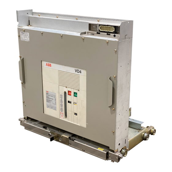
VD4
Installation and service instructions
12 ... 24 kV - 630 ... 2500 A - 16 ... 31.5 kA
Table of
Contents
Previous
Page
Next
Page
1
2
3
4
5
Advertisement
Table of Contents
Need help?
Do you have a question about the VD4 12 and is the answer not in the manual?
Ask a question
Questions and answers
Related Manuals for ABB VD4 12
Circuit breakers ABB VD4 Product Manual
Medium voltage circuit-breakers (64 pages)
ABB VD4 Instruction Manual
Vacuum circuit breaker with embeded poles 36...40,5v, 1250...1500a, 25...31,5ka (32 pages)
ABB VD4 24 Installation And Service Instructions Manual
Vd4 series 12 - 24 kv; 630 - 2500 a; 16 - 31.5 ka (48 pages)
ABB Vmax 12 Installation And Service Instructions Manual
12...17.5 kv - 630...1250 a - 16...31.5 ka (36 pages)
This manual is also suitable for:
Vd4 17
Vd4 24
Table of Contents
Save PDF
Print
Rename the bookmark
Delete bookmark?
Delete from my manuals?
Login
Sign In
OR
Sign in with Facebook
Sign in with Google
Upload manual
Upload from disk
Upload from URL


Need help?
Do you have a question about the VD4 12 and is the answer not in the manual?
Questions and answers