Table of Contents
Advertisement
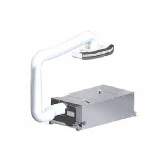
UB1 AIR CONDITIONING UNIT
OPERATING MANUAL
OPERATING INSTRUCTIONS:
Carefully read these instructions before operating your new air-conditioner.
© 2010 DENSO Automotive Systems Australia Pty. Ltd
All rights reserved.
AUSTRALIAN AUTOMOTIVE AIR
This book may not be reproduced or copied, in whole or
in part, without the written permission of the publisher.
AL00500054E
DENSO reserves the right to make changes without prior
notice.
Advertisement
Table of Contents

Related Manuals for Denso UB1


Summary of Contents for Denso UB1
-
Page 1: Operating Manual
© 2010 DENSO Automotive Systems Australia Pty. Ltd All rights reserved. AUSTRALIAN AUTOMOTIVE AIR This book may not be reproduced or copied, in whole or in part, without the written permission of the publisher. AL00500054E DENSO reserves the right to make changes without prior notice. -
Page 2: Table Of Contents
UB1 WARRANTY REGISTRATION CARD TABLE Of CONTENTS 1. Foreword ............1 NAME: 1.1 Definition of Terms ......1 2. Inventory............1 ADDRESS: 3. General Information ........2 4. Controls ............4 4.1 Remote Control ......4 P/CODE: 4.2 Unit .............6 5. Operation ............7 PHONE No: The unit serial number can 6. -
Page 3: Foreword
1. FOREWORD Thank you for purchasing the AAA UB1 Air Conditioning Unit. Before using the unit, thoroughly read this manual and follow the instructions on how to operate this product. Keep this manual in the caravan, and in case the caravan is sold to another party, make sure that this manual is passed on to the next owner. -
Page 4: General Information
3. GENERAL INFORMATION The ability of the air-conditioner to maintain a desired temperature depends upon the heat entering or leaving your vehicle. The following simple guidelines should be followed to achieve the best comfort, lowest energy use and quietest operating noise. a. - Page 5 WARNING This appliance is not intended for use by persons (including children) with reduced physical, sensory or mental capabilities, or lack of experience and knowledge, unless they have been given supervision or instruction concerning use of the appliance by a person responsible for their safety.
-
Page 6: Controls
4. CONTROLS COOLING HEATING TEMP. SETTING TIMER FAN SPEED 4.1 REMOTE CONTROL Power On/Off switch Temperature Decrease Lowers the desired room temperature (16-30°C) Temperature Increase Raises the desired room temperature (16-30°C) D/ Fan Speed Cooling/Fan Mode Cycles the interior fan through 3 speed settings Heating Mode Fan speed is controlled automatically regardless of remote setting. - Page 7 Timer On Timer Pressing this button while the unit is off will set the on timer. Each button press adds 1 hour to the wait time until the unit starts (1-12 hours). After cycling through 12 hours, the next button press will cancel the on timer. Off Timer Pressing this button while the unit is on will set the off timer.
-
Page 8: Unit
4.2 UNIT H/ Directional Airflow Controls Horizontal airflow directional control. Power Indicator (Blue) Illuminates when the air-conditioner is switched on. Infrared Remote Control Receiver Electronic receiver for remote control signal. Quick Cool Mode Indicator (White) Illuminates while the air-conditioner is operating in quick cool mode. -
Page 9: Operation
5. OPERATION Connect the air-conditioner power supply cord to a 10A power outlet. CAUTION Always ensure that the power supply cord is fully uncoiled before operating the unit to prevent overheating. The power cord must be routed so that it cannot be damaged during use or when in transit. - Page 10 The compressor and exterior fan speed are microprocessor controlled to automatically ensure a long life for your air-conditioner while maintaining the best possible comfort. Depending upon the conditions and air-conditioner settings, you may notice some of the following: Automatic Compressor Start Protection: The compressor start may be delayed for up to 3 minutes after selecting cooling or heating mode.
-
Page 11: Maintenance
6. MAINTENANCE WARNING Always disconnect the air-conditioner from the power supply before performing any maintenance. 6.1 INLET AIR FILTER A dust filter is fitted to the return air inlet of the air-conditioner. This filter is essential to prevent a build up of dust blocking the evaporator. The filter (Part No. TA145520-2000) must be cleaned by vacuuming at least twice per year. -
Page 12: Remote Control Batteries
CAUTION If you intend to travel through water that is higher than the floor of your vehicle, all underfloor vents and drains must be sealed to prevent water entry and damage to your air-conditioner. Be sure to unseal all openings before operating the air- conditioner. -
Page 13: General Condition
Check that the flexible duct and remote cable are secure free from damage. If any problems are found, immediately disconnect the unit & contact your nearest service agent for assistance. 7. TECHNICAL DATA Unit: UB1 Air-conditioner Part No. TA448006-6220 Application: Caravan, camper and pop-top recreational vehicles Nominal Cooling Capacity: 2.6 kW (T1) -
Page 14: Wiring Diagram
7.1 WIRING DIAGRAM ... -
Page 15: Troubleshooting
8. TROUBLESHOOTING Symptom Cause Remedy Unit does not Power supply is OFF Check supply cord, outlet & supply circuit breaker. operate When the supply is connected, the POWER & QUICK COOL LED’s should flash once to indicate that the supply has been switched on. Control cable is Check that the control cable is securely connected disconnected... - Page 16 Compressor There system Ensure that the unit is being used within its cuts or does has a number of operating temperature range. Refer to section 3 for not start. inbuilt protection a description of some of the operating modes you mechanisms to protect may experience.
-
Page 17: Warranty Details
This warranty applies where the caravan is used solely within Australia. If warranty service is required, the purchaser or service agent must contact DENSO for service approval prior to repair. Contact can be made as below during normal business hours Monday to Friday. -
Page 18: Service Dealer Network
9.1 NATIONAL SERVICE DEALER NETWORK (15) WESTERN AUSTRALIA (5) VICTORIA (1) Batavia Coast Coromal Sandown Coromal Caravans 215 Flores Road 845 – 847 Princes Highway Geraldton, W.A 6530 Springvale, VIC 3171 Phone: 08 9923 1601 Phone: 03 9574 6077 admin@1800caravan.com.au info@coromalcaravanssandown.com.au Cameron Caravans NEW SOUTH WALES (5)
Need help?
Do you have a question about the UB1 and is the answer not in the manual?
Questions and answers