Table of Contents
Advertisement
Advertisement
Table of Contents

Related Manuals for ADT Pulse MDC835


Summary of Contents for ADT Pulse MDC835
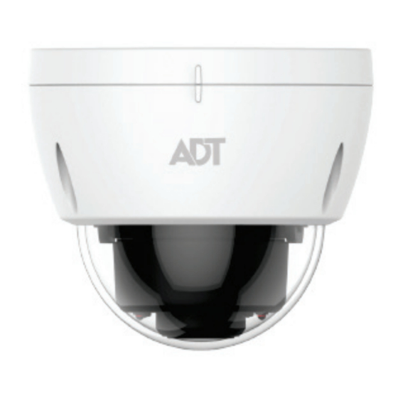
- Page 1 ADT Pulse Interactive Solutions ℠ MDC835 Mini Dome Camera Installation Guide...
-
Page 2: Table Of Contents
Installation...................... 5 CHAPTER 3 CEILING MOUNTING ............... 5 Ceiling Mounting Installation ................5 CHAPTER 4 ADT PULSE ENROLLMENT ............. 9 Wired Connection to the Gateway Using the Pulse Portal ....... 9 Using WPS with PIN to Enroll the Camera ............ 12 If the Camera Continually Goes Offline ............ -
Page 3: Chapter 1 Introduction
20 meters at night. This device is also an all-in-one camera that has automatic day-night switching, built-in heater and Mechanical Pan/Tilt/Rotate orientation adjustment. The camera is intended for use in ADT Pulse. Features •... - Page 4 Chapter 1 Introduction • Supports 802.11n Wireless Standard. The 802.11n standard provides for backward compatibility with the 802.11b/g wireless network. • Supports WPS. Wi-Fi Protected Setup (WPS) can simplify the process of connecting the IP Camera to the wireless network by pin code mode via ADT pulse.
-
Page 6: Physical Details
Chapter 1 Introduction Physical Details Front/Rear Panel Figure 1: Front/Rear Panel IR LEDs They are used to provide illumination for night time. Please ensure that the two IR LEDs can be revealed in the transparent Dome. Light Sensor This is a hardware sensor to detect lux. Please ensure that the light sensor can be revealed in the transparent Dome. - Page 7 Chapter 1 Introduction Power Interface Connect the two wires of the supplied cable to the terminal adapter. Do not use the other terminal adapters; doing so may damage the camera. Power Indicator On (Green) - Power on. (Green, Amber, Off – No power. Blue) Blinking (Green) - The LED will blink during start up or wireless connection is under association.
- Page 8 Chapter 1 Introduction The button serves three functions on the camera. WPS/Reset/ Image Flip Button WPS Pin Code Mode. When pressed and held for 5 seconds during the Pulse enrollment process, the camera creates an encryption-secured wireless connection. Reset. When pressed and held over 15 seconds, the camera reboots and the settings are restored to default values.
-
Page 10: Package Contents
Chapter 1 Introduction Package Contents The following items are included: IP Camera with pigtail (DC-IN and RJ45) Terminal Adapter Wall Mount Screw Package L Tool (T10) Spice Connector... -
Page 11: Chapter 2 Basic Setup
1. Make the Connection Using a Wired Connection If you are using a wired connection to the MDC835, connect a standard Ethernet cable (not included) to the LAN port of the supplied cable of the camera and the Pulse Gateway or Total Security (TS) Base panel. - Page 12 After startup is completed, the Power LED should remain ON. 4. Enroll the Camera in ADT Pulse This process is described in the later chapter. After the enrollment, please check the image orientation. You may rotate the image 180 degrees by fast-clicking the WPS/Reset/Image Flip button twice.
-
Page 13: Chapter 3 Ceiling Mounting
This Chapter provides details for final ceiling mounting of the IP Camera Ceiling Mounting Installation NOTE: Ensure that the camera is configured and enrolled in ADT Pulse before permanently mounting it. NOTE 1. Locate an unused indoor outlet to plug into the terminal adapter. - Page 14 Chapter 3 Ceiling Mounting Figure 4: Removing the bubble from the Camera 4. If using the anchors, insert them into the mounting holes. 5. Align the three mounting holes of the camera stand with the three holes and mount the camera stand on the ceiling using the provided screws.
- Page 15 Chapter 3 Ceiling Mounting CAUTION: Do not entwine the antenna while connecting the LVDS cable. Figure 7: LVDS Cable 7. Attach the bubble to the camera and tighten it using the three screws. NOTE: You can use the marks for alignment while attaching the bubble to the camera.
- Page 16 Chapter 3 Ceiling Mounting CAUTION: Make sure to tighten up the three screws in order to prevent water from the camera. CAUTION: Be careful not to let the bubble cover the light sensor and damage the LVDS cable while attaching the bubble to the camera.
-
Page 17: Chapter 4 Adt Pulse Enrollment
MDC835 Camera into the ADT Pulse network. This process uses the Wi-Fi Protected Setup (WPS) with PIN method to wirelessly enroll the Camera to the gateway via the ADT Pulse Portal or TS Installer App. Wired Connection to the Gateway Using the Pulse Portal Set up the Camera, as described in the previous chapter. - Page 18 Chapter 4 ADT Pulse Enrollment In the Manage Devices Assistant, click Cameras. Click the picture of the MDC835 or select it from the drop-down list, and then click the Continue button.
- Page 19 Chapter 4 ADT Pulse Enrollment MDC835 Assign the a unique Camera Name (usually based on camera the location of the ) in the space provided, and camera’s then type in the MAC ID. Click the Continue button. camera Ensure that the is connected to the device port of the Gateway using the Ethernet cable.
-
Page 20: Using Wps With Pin To Enroll The Camera
Chapter 4 ADT Pulse Enrollment 10. After the Camera has connected and the button is no longer grayed out, click Continue. 11. Click Finish. The Pulse enrollment is complete. camera 12. Disconnect the from the Gateway and remove from power. - Page 21 Chapter 4 ADT Pulse Enrollment Locate the camera’s PIN number on the label on the rear of the camera. Enter the PIN number in the WPS PIN field. Ensure that the camera is powered on and that the Power LED is flashing green.
- Page 22 Chapter 4 ADT Pulse Enrollment 10. Press and hold the WPS/RESET/Image Flip button on the camera for 5seconds to establish a wireless connection. The Power LED flashes amber as the gateway attempts to connect to the camera. The wireless connection is successful when the Power LED turns solid green.
- Page 23 Chapter 4 ADT Pulse Enrollment The Pulse enrollment is complete. The newly-added device appears in the Cameras list. 12. At the top left of the screen, click Go Back. 13. Wait until the Power LED and Network LED are both lit solid green/blue, and then disconnect the camera from power.
-
Page 24: If The Camera Continually Goes Offline
Chapter 4 ADT Pulse Enrollment If the Camera Continually Goes Offline If after enrolling it the camera, it continually goes offline (Power LED blinks continually), the camera will automatically attempt to recover the wireless connection. If the camera cannot recover on its own, take the following measures to re-establish the Wi-Fi connection. -
Page 25: Appendix A Specifications
Appendix A Specifications MDC835 IP Camera Dimensions (DxH) 4.33” x 3.62” (110mm x 92mm) Lens F1.8. DFOV 75° Video H.264 and MJPEG Compression Image Resolution 16:9 720p (1280x 720), QHD (640x360), VGA (640x480), QVGA (320x240) Mixed Mode (720p, VGA, QVGA) Operating -40°F to 122°F (-40°C to 50°C) -
Page 26: Fcc Radiation Exposure Statement
Appendix turning the equipment off and on, the user is encouraged to try to correct the interference by one of the following measures: • Reorient or relocate the receiving antenna. • Increase the separation between the equipment and receiver. • Connect the equipment into an outlet on a circuit different from that to which the receiver is connected. - Page 27 Appendix Radiation Exposure Statement: This equipment complies with IC radiation exposure limits set forth for an uncontrolled environment. This equipment should be installed and operated with minimum distance 20cm between the radiator & your body. Déclaration d'exposition aux radiations: Cet équipement est conforme aux limites d'exposition aux rayonnements IC établies pour un environnement non contrôlé.
- Page 28 Appendix Mounting Template...
Need help?
Do you have a question about the MDC835 and is the answer not in the manual?
Questions and answers