Table of Contents
Advertisement
Advertisement
Table of Contents

Related Manuals for ADT Pulse OC810


Summary of Contents for ADT Pulse OC810
- Page 1 Network Camera User’s Guide...
-
Page 2: Table Of Contents
Table of Contents CHAPTER 1 INTRODUCTION....................1 Overview ..........................1 Physical Details - Network Camera ................. 4 Package Contents ......................6 CHAPTER 2 BASIC SETUP ....................7 System Requirements......................7 Installation - Network Camera..................8 Setup using the Windows Wizard ..................9 CHAPTER 3 VIEWING LIVE VIDEO ................ - Page 3 Installation ........................64 System Tray Icon......................65 LiveView Screen ......................66 Camera Setup ........................67 LiveVew Program - for Streams Live Viewing ............. 69 View Recordings Program - for Streams Recording............ 71 Setup Program - for Streams Configuration..............73 CHAPTER 7 TROUBLESHOOTING .................. 76 Overview ..........................
-
Page 4: Chapter 1 Introduction
Chapter 1 Introduction This Chapter provides details of the Network Camera's features, components and capabilities. Overview The Network Camera has an Integrated Microcomputer and a high quality Omni Vision CMOS Sensor, enabling it to display high quality live streaming video over your wired LAN, the Internet, and for the Network Camera, an 802.11N Wireless LAN. -
Page 5: Internet Features
• Stream Live Video to Multiple Users. The video encoder and HTTP/HTTPS server built into the camera generate a ready-to-view video stream. Just connect to the camera using your Web browser or the provided Windows utility to view live video. •... -
Page 6: Wireless Features
Wireless Features • Supports 11n Wireless Stations. The 802.11n Draft standard provides for backward compatibility with the 802.11b standard, so 802.11n, 802.11b and 802.11g Wireless stations can be used simultaneously. • Wired and Wireless Network Support. The Network Camera supports either wired or wireless transmission. -
Page 7: Physical Details - Network Camera
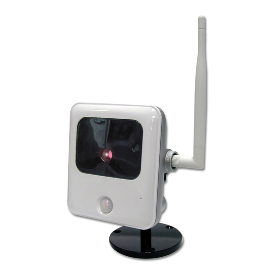
Physical Details - Network Camera Front - Network Camera Figure 2: Front Panel No physical adjustment is required or possible for the lens, but Lens you should ensure that the lens cover remain clean. The image quality is degraded if the lens cover is dirty or smudged. Microphone The built-in microphone is mounted on the front. - Page 8 Rear - Network Camera Figure 3: Rear Panel Antenna Attach the supplied antenna here. The antenna is adjustable; best results are usually obtained with the antenna positioned vertically. Power Input Connect the supplied 12V power adapter here. Do not use other power adapters;...
-
Page 9: Package Contents
Package Contents The following items should be included: If any of these items are damaged or missing, please contact your dealer immediately. 1. Network Camera 2. Installation CD-ROM 3. Quick Installation Guide 4. Power adapter 5. Camera Mounting Bracket (Base, Stand and Swivel Connector) 6. -
Page 10: Chapter 2 Basic Setup
Chapter 2 Basic Setup This Chapter provides details of installing and configuring the Network Camera. System Requirements • To use the wired LAN interface, a standard 10/100BaseT hub or switch and network cable is required. • To use the Wireless interface on the wireless model, other Wireless devices must be compliant with the IEEE802.11b, IEEE802.11g or IEEE 802.11n specifications. -
Page 11: Installation - Network Camera
Installation - Network Camera 1. Assemble the Camera On the Wireless Model, screw the supplied antenna to the mounting point on the rear. 2. Connect the LAN Cable Connect the Network Camera to a 10/100BaseT hub or switch, using a standard LAN cable. -
Page 12: Setup Using The Windows Wizard
Setup using the Windows Wizard Initial setup should be performed using the supplied Windows-based setup Wizard. This program can locate the Network Camera even if its IP address is invalid for your network. You can then configure the Network Camera with appropriate TCP/IP settings for your LAN. Subsequent administration can be performed with your Web browser, as explained in Chapter 5 - Web-based Management. - Page 13 • Select the desired Camera from the list on the left. The current settings for the selected Camera will be displayed in the table on the right. • Click Next to continue. 3. You will be prompted to enter the Administrator Name and Administrator Password, as shown below.
- Page 14 Figure 9: Fixed or Dynamic IP Selection • Fixed IP Address is recommended, and can always be used. • Dynamic IP Address can only be used if your LAN has a DCHP Server. • PPPoE (PPP over Ethernet) is the most common login method, widely used with DSL modems.
- Page 15 Click Next to continue. 7. If you chose PPPoE, the following PPPoE Settings screen will be displayed. Figure 11: PPPoE Settings Screen • Enter the User Name provided by your ISP. • Enter the Password for the user name above. Click Next.
- Page 16 Figure 13: Confirm Screen 10. After clicking OK, you will see the screen below. Figure 14: Final Screen Clicking the Install Utility button will install the Viewing/Recording utility described in Chapter 6 - Windows Viewing/Recording Utility. 11. Click Exit to end the Wizard. Setup is now complete.
-
Page 17: Chapter 3 Viewing Live Video
Chapter 3 Viewing Live Video This Chapter provides basic information about viewing live video. Overview After finishing setup via the Windows-based Wizard, all LAN users can view live video using Internet Explorer on Windows. This Chapter has details of viewing live video using Internet Explorer. But many other powerful features and options are available: •... - Page 18 Figure 15: Home Screen 5. Click View Video. 6. If the Administrator has restricted access to known users, you will then be prompted for a username and password. Enter the name and password assigned to you by the Network Camera administrator. 7.
-
Page 19: Connecting To A Camera Via The Internet
Connecting to a Camera via the Internet You can NOT connect to a camera via the Internet unless the camera Administrator has configured both the camera and the Internet Gateway/Router used by the camera. See Making Video available from the Internet in Chapter 4 - Advanced Viewing Setup for details of the required configuration. - Page 20 4. When you connect, the following screen will be displayed. Figure 17: Home Screen 5. Click View Video. 6. If the Administrator has restricted access to known users, you will then be prompted for a username and password. Enter the name and password assigned to you by the Network Camera administrator. 7.
-
Page 21: Viewing Live Video
Viewing Live Video After installing the ActiveX component, you will be able to view the live video stream in its own window, as shown below. Figure 19: View Video Screen There are a number of options available on this screen, accessed by select list, button or icon. See the table below for details. - Page 22 Flip. Click this to have the image swapped top-to-bottom. Full Size. When using high-resolution mode, click this button to see the full size of the image. Setup. Select the desired folder to save the file.
-
Page 23: Chapter 4 Advanced Viewing Setup
Chapter 4 Advanced Viewing Setup This Chapter provides information about the optional settings and features for viewing video via the Network Camera. This Chapter is for the Camera Administrator only. Introduction This chapter describes some additional settings and options for viewing live Video: •... - Page 24 3. Make the required adjustments, as explained below, and save your changes. Default Streaming Select the default channel for streaming from the drop-down list. Channel Streaming 1 Settings (MJPEG) Video Format This displays the default format. Resolution Select the desired video resolution format. Select the desired option.
-
Page 25: Controlling User Access To The Video Stream
Controlling User Access to the Video Stream By default, anyone can connect to the Network Camera and view live Video at any time. If desired, you can limit access to scheduled times, and also restrict access to known users. To Control User Access to Live Video: 1. -
Page 26: Making Video Available From The Internet
Making Video available from the Internet If your LAN is connected to the Internet, typically by a Broadband Gateway/Router and Broadband modem, you can make the Network Camera available via the Internet. You will need to configure your Router or Gateway to allow connections from the Internet to the camera. Router/Gateway Setup Your Router or Gateway must be configured to pass incoming TCP (HTTP) connections (from Internet Viewers) to the Network Camera. -
Page 27: Network Camera Setup
Network Camera Setup The Network Camera configuration does NOT have be changed, unless: • You wish to change the port number from the default value. • You wish to use the DDNS (Dynamic DNS) feature of the Network Camera. HTTPS Port Configuration Normally, HTTP (Web) connections use port 80. - Page 28 Figure 24: DDNS Screen 4. Operation is then automatic: • The Network Camera will automatically contact the DDNS server whenever it detects that the Internet IP address has changed, and inform the DDNS server of the new IP address. • Internet users can then connect to the camera using the Domain Name allocated by the DDNS service provider.
-
Page 29: Viewing Live Video Via The Internet
Viewing Live Video via the Internet Clients (viewers) will also need a broadband connection; dial-up connections are NOT recommended. Viewing Live Video Using your Web Browser If using your Web browser, you need to know the Internet IP address (or the Domain name) of the camera's Router/Gateway, and the correct port number. -
Page 30: Motion Detection Alerts
Motion Detection Alerts The Motion Detection feature can generate an Alert when motion is detected. The Network Camera will compare consecutive frames to detect changes caused by the movement of large objects. But the motion detector can also be triggered by: •... -
Page 31: Chapter 5 Web-Based Management
Chapter 5 Web-based Management This Chapter provides Setup details of the Network Camera’s Web-based Interface. This Chapter is for the Camera Administrator only. Introduction The Network Camera can be configured using your Web Browser. The Network Camera must have an IP address which is compatible with your PC. The recommended method to ensure this is to use the supplied Windows-based Wizard, as described in Chapter 2 - Basic Setup. -
Page 32: Welcome Screen
Welcome Screen When you connect, the following screen will be displayed. Figure 27: Welcome Screen The menu options available from this screen are: • View Video - View live Video using your Web Browser. See Chapter 3 - Viewing Live Video for details. -
Page 33: Administration Menu
Administration Menu Clicking on Administration on the menu provides access to all the settings for the Network Camera. The Administration menu contains the following options: Setup • System • Network • Wireless • DDNS • IP Filter Video & Audio •... -
Page 34: System Screen
System Screen After clicking Administration on the main menu, or selecting System on the Administration menu, you will see a screen like the example below. Figure 28: System Screen Data - System Screen System Settings This displays the ID for the Network Camera. Device ID Camera Name Enter the desired name for the Network Camera. - Page 35 Time Zone Choose the Time Zone for your location from the drop-down list. If your location is currently using Daylight Saving, please enable the Adjust for daylight saving checkbox. Enable or disable the Time Server feature as required. Network Time Protocol If Enabled, the Network Camera will contact a Network Time Server at regular intervals and update its internal timer.
-
Page 36: Network Screen
Network Screen This screen is displayed when the Network option is clicked. Figure 29: Network Screen... - Page 37 Data - Network Screen Network There are 3 connection types: Internet Connection Type • Obtain Address Automatically (DHCP): If selected, the Network Camera will obtain its IP address and related information from a DHCP Server. Only select this option if your LAN has a DHCP Server.
- Page 38 HTTP/HTTPS This sets the port number for HTTP/HTTPS connections to the Camera, whether for administration or viewing video. The HTTP (HyperText Transfer Protocol) is used for the standard of transferring files (text, graphic images and other multimedia files) on the World Wide Web. The default HTTP port is 1024. HTTPS (Hypertext Transfer Protocol Secure) can provide more secure communication with the SSL/TLS protocol, which support data encryption to HTTP clients and servers.
- Page 39 Enable Traversal If enabled, HTTP connections (from your Web Browser or the Viewer and Recorder utility) can use secondary port instead of port 80 (the standard HTTP port) to access the camera. Bonjour Enable Bonjour If enabled, the Network Camera can be accessed through a Service "Bonjour"...
-
Page 40: Wireless Screen
Wireless Screen This screen is displayed when the Wireless menu option is clicked. Figure 30: Wireless Screen Data - Wireless Screen Wireless Network Click the "Site Survey" button and select from a list of available Site Survey APs. WSC PIN Code It displays the WSC PIN code number for the camera. - Page 41 • Channel No. In Infrastructure mode, this setting is ignored. The Network Camera will use the Channel set on the Access Point. • For Ad-hoc mode, select the Channel you wish to use on your Network Camera. Other Wireless stations should use the same setting.
- Page 42 WPA/WPA2 Personal Shared Key Enter the key value. Data is encrypted using a key derived from the network key. Other Wireless Stations must use the same network key. The PSK must be from 8 to 63 characters or 64 hex characters in length.
-
Page 43: Ddns Screen
DDNS Screen Many Internet connections use a "Dynamic IP address", where the Internet IP address is allocated whenever the Internet connection is established. This means that other Internet users don't know the IP address, so can't establish a connection. DDNS is designed to solve this problem, as follows: •... - Page 44 Account/E-Mail Enter the login name for the DDNS account. Password/Key Enter the password for the DDNS account. Check WAN IP Set the schedule for checking if the Internet IP address has Address changed. If the IP address has changed, the DDNS Server will be notified.
-
Page 45: Ip Filter
IP Filter The IP Filter feature allows administrator to control Network Camera access by filtering IP addresses. This screen is displayed when the IP Filter menu option is clicked. Figure 32: IP Filter Screen Data - IP Filter Screen IP Filter Select the desired method to perform the IP address (or addresses) IP Filter filtering function. -
Page 46: Streamings
Streamings This screen is displayed when the Streamings menu option is clicked. If you want to view streaming via the cell phone: 1. Cell phone should be supported by 3GPP protocol. 2. Enter 554 for RTSP port number in the Network screen. 3. - Page 47 Data - Streamings Screen Select the default channel for streaming from the drop-down list. Default Streaming Channel Streaming 1 Settings (MJPEG) Video Format This displays the default format. Resolution Select the desired video resolution format. Fixed Video Select the desired option. The default fix quality is set to Normal. Quality Select the desired Maximum frame rate for the video stream.
-
Page 48: Video & Audio Screen
Video & Audio Screen This screen is displayed when the Video & Audio menu option is clicked. Figure 34: Video & Audio Screen Data - Video & Audio Screen Video Adjustment Select the power line frequency (50Hz or 60Hz) used in your region, Power Line to improve the picture quality under florescent lighting. - Page 49 Enable Text Enable this setting if you want text to be displayed on the Video Display image, and enter the desired text - up to 20 characters. This feature is often used to identify each camera when multiple cameras are installed.
-
Page 50: Video Access Screen
Video Access Screen This screen is displayed when the Video Access option is clicked. Figure 35: Video Access Screen Data - Video Access Screen User Access • If disabled (default) - No login required. Users do not have to Enable Security provide a username and password when they connect to the Checking camera for viewing video. - Page 51 Add New Schedule Choose the desired option for the period. Start Time Enter the start time using a 24 hr clock. End Time Enter the end time using a 24 hr clock. Click this button to add a new period. Clear Use this button to clear the input fields.
-
Page 52: User Database Screen
User Database Screen This screen is displayed when the User Database option is clicked. Figure 36: User Database Screen Data - User Database Screen Existing Users This displays all users you have entered into the User database. If User List you have not entered any users, this list will be empty. -
Page 53: Motion Detection Screen
Motion Detection Screen This screen is displayed when the Motion Detection option on the Event menu is clicked. Figure 37: Motion Detection Screen Data - Motion Detection Screen Motion Detection You can set the full screen or selected areas of the video image to be Set Detection examined. -
Page 54: Audio Detection Screen
Audio Detection Screen This screen is displayed when the Audio Detection option on the Event menu is clicked. Figure 38: Audio Detection Screen Data - Audio Detection Screen Audio Detection It displays the current volume of the environment. Current Volume Triggered Drag the bar to set the volume for triggering. -
Page 55: E-Mail Screen
E-Mail Screen This screen is displayed when the E-Mail option on the Event menu is clicked. Figure 39: E-Mail Screen Data - E-Mail Screen Primary/Secondary SMTP Server Enter the address of the SMTP (Simple Mail Transport Protocol) SMTP Server Server to be used to send E-Mail. Address Authentication Select the desired Authentication type for the SMTP Server. - Page 56 Subject Enter the desired text to be shown as the "Subject" for the E-Mail when it is received. Subject can not exceed 48 alphanumeric characters.
-
Page 57: Ftp Screen
FTP Screen This screen is displayed when the FTP option on the Event menu is clicked. Figure 40: FTP Screen Data - FTP Screen Primary/Secondary FTP Enter the address of the FTP Server. FTP Server Port Enter the Port of the FTP Server to be connected. Enter your login name for the FTP Server. -
Page 58: Http Screen
HTTP Screen This screen is displayed when the HTTP option on the Event menu is clicked. Figure 41: HTTP Screen Data - HTTP Screen HTTP Notification Enter the URL of your HTTP notification server. User Name Enter the user name of your HTTP server. Enter the password to match the user name above. -
Page 59: Smb/Cifs Client Screen
SMB/CIFS Client Screen This screen is displayed when the SMB/CIFS Client option on the Event menu is clicked. Figure 42: SMB/CIFS Client Screen Data - SMB/CIFS Client Screen SMB/CIFS Client Browse SMB/CIFS Click Browse button to select the desired SMB/CIFS server. Server Server Name Enter the name of your SMB/CIFS server. -
Page 60: Event Trigger Screen
Event Trigger Screen This screen is displayed when the Event Trigger option on the Event menu is clicked. Figure 43: Event Trigger Screen Data - Event Trigger Screen Event Schedule The Event Schedule shows all of the event types currently Schedule List configured in the Network Camera, along with various information about their configuration, as listed below:... - Page 61 Interval Select the desired option for the events interval. (* "0" = No Delay) • PIR - If the PIR sensor detects a human body, it will be used to Trigger by trigger events. • Audio Detection - The sound detection can be used to trigger events.
-
Page 62: Maintenance Screen
Maintenance Screen Figure 44: Maintenance Screen Data - Maintenance Screen Administrator Login Enter the name for the Administrator here. Administrator Spaces, punctuation, and special characters must NOT be used in the name. The password for the Administrator. Administrator Password Verify Password Re-enter the password for the Administrator, to ensure it is correct. - Page 63 Backup & Restore Backup Click Backup button to save the current configuration information to a Configuration text file. File It is suggested to backup the configuration file, in order to restore the camera easily. Restore Click Restore button to reinitialize the camera to load the new updated Configuration software.
-
Page 64: Status Screen
Status Screen Figure 45: Status Screen Data - Status Screen System Device Name This shows the name of the Network Camera. Description This shows the description of the Network Camera, such as location. F/W version The version of the current firmware installed. Network MAC Address The current IP address of the Network Camera. - Page 65 Wireless WSC PIN Dode It displays the current WSC PIN code. Network Type This shows the Network Type currently in use (Ad-hoc or Infrastructure). SSID This displays the wireless SSID. Channel This shows the wireless channel currently used. The current security setting for Wireless connections. Security Signal Strength This shows the strength of the signal.
-
Page 66: Log Screen
Log Screen This screen displays a log of system activity. Figure 46: Log Screen Data - Log Screen This is a log of system activity. System Log Refresh Click this to update the data shown on screen. Button Click this button to restart the log. Clear Log Enable Syslog Check the box to enable the System Log Server feature. -
Page 67: Chapter 6 Windows Viewing/Recording Utility
Chapter 6 Windows Viewing/Recording Utility This Chapter describes how to use the supplied Utilities package to view and listen the live streams generated by the Network Camera. Overview The Utilities package includes following three functions: • LiveView - to view/listen the live streams. •... -
Page 68: System Tray Icon
Figure 47: Welcome Screen 2. Click the Install Utility button to start the installation of the Utilities package. 3. Follow the prompts to complete the installation. 4. After the installation, double click the Monitor icon on the desktop or click Monitor menu item in the Windows main program menu to launch the Utilities. -
Page 69: Liveview Screen
LiveView Screen When Utility launched, the Camera Utility screen like the example below will be displayed. Figure 49: Main Screen If no cameras have been defined and added to the Utilities, no video will be displayed. Utilities should be configured first to view the camera streams. See the following section for information on defining a camera. -
Page 70: Camera Setup
Camera Setup To define a camera and associate it with a Channel Number: 1. Click the Setup icon on the main screen. You will see a screen like the example below. Figure 50: Cameras Setup Screen 2. Add desired Network Camera to the Camera List: •... - Page 71 • Click the Test Camera button to check that a connection and login can be performed successfully. • Click Add button. The camera will now appear in the Camera List. Cameras Data Camera list This displays the cameras you've added, if any. Use the Delete button to delete the selected camera in the list.
-
Page 72: Livevew Program - For Streams Live Viewing
LiveVew Program - for Streams Live Viewing You can view live video in the Monitor screen. The built-in software can let you view up to 9 cameras on a single computer screen at one central location. The following table lists the icons displayed on the Monitor screen: View Layout. - Page 73 Move Control. Use this to move the camera to the desired position. There may a short delay after clicking the desired icon. You should wait a couple of seconds rather than click again. Or you can drag the vertical or horizontal slider bar to have quicker movement of the Network Camera to the desired position.
-
Page 74: View Recordings Program - For Streams Recording
View Recordings Program - for Streams Recording To access the saved recordings of the Cameras, click View Recordings icon on the top of the screen, then you will see a screen like following. Figure 51: View Recordings Screen Searching Recorded Streams Files Skip to Next Record. - Page 75 Recording Bar. It displays the recordings that match your requests. Calendar. Choose the date of the calendar for finding desired recordings.
-
Page 76: Setup Program - For Streams Configuration
Setup Program - for Streams Configuration There are 3 tabs of the Setup program: • Cameras • Recording Options • Settings For the Cameras configuration, please refer to the Camera Setup for details. You can record the streams from camera by pressing the Instant Record button in the Monitor program as mentioned in the "... - Page 77 4. Press Add button to add the schedule. You will see all the schedules in the recording list. Settings Clicking the Settings tab on the Configuration program to make change of default Utilities parameter settings. Figure 53: Settings Screen Data - Settings Recording Path This is the Drive and Folder on your PC/Notebook where Recording...
- Page 78 Disk Space for Each Camera Recording Total Disk Space This displays the total size of the selected disk. Available Disk Space This displays the available space of the selected disk for storing recordings. Enable Disk space Enable this if you wish to limit the disk space used by video limitation recordings.
-
Page 79: Chapter 7 Troubleshooting
Chapter 7 Troubleshooting This chapter covers the most likely problems and their solutions. Overview This chapter covers some common problems that may be encountered while using the Network Camera and some possible solutions to them. If you follow the suggested steps and the Network Camera still does not function properly, contact your dealer for further advice. - Page 80 If you are just trying to view Video, the User Name/Password prompt indicates that the Administrator has restricted access to specified users. Ask the Administrator for your User Name and Password. Problem 4 I can't connect to the Network Camera using a Wireless connection. 1) If a LAN cable is connected to the LAN port, the Wireless interface is Solution 4 disabled.
-
Page 81: Appendix A Specifications
Appendix A Specifications Network Camera Model Network Camera Dimensions 94mm (W) x 103mm (H) x 37mm (D) Operating Temperature 0° C to 45° C Storage Temperature -20° C to 70° C Network Protocols TCP/IP, HTTP, HTTPS, DHCP, SMTP, FTP, UPnP, DDNS, NTP, RTP, RTCP, RTSP, SMB Network Interface 1 Ethernet 10/100BaseT (RJ45) LAN connection... -
Page 82: Copyright Notice
Copyright Notice Many software components are covered by the GNU GPL (General Public License). Some are covered by other Licenses. You can check more details of each applicable license by clicking the License button in the Maintenance screen. -
Page 83: Appendix B Network Camera Http Cgi
Appendix B Network Camera HTTP CGI User-lev el CGI commands (user level privilege) Notes: If camera is in privacy mode, it will reject the streaming/snapshot request with “406 Not Acceptable” and stop video post for event. Video and Image commands Stream M-JPEG video HTML page for the end user Method: GET... - Page 84 Server Push page for the programmer Method: GET URL: http://<ip>/img/video.mjpeg (utility) The camera will check the request User-Agent parameter in HTTP header to identify the client type. The camera will regard the client as MSIE if there is the string “MSIE”, regard the client as SerComm OCX if there are the strings “CameraActiveX”...
- Page 85 23-24 Bit Rate The audio bit rate. 0x02 (02): 2 KbytesPerSecond 0x04 (04): 4 KbytesPerSecond 0x08 (08): 8 KbytesPerSecond Version The version number. It is 0x02 (02). 26-45 Time The ASCII string to present the current camera time. (Not String used) Padding The padding flag...
- Page 86 … content-type: text/plain\r\n \r\n current_ resolution=A\r\n current_framerate=B\r\n The A and B are in the following format. Parameter Value and description Image resolution 1: 160x120 (or 160x128, 176x120 (NTSC)/ 176x144(PAL), depends on models) 2: 320x240 (or 352x240(NTSC)/ 352x288(PAL), depends on models) 3: 640x480 (or 704x480(NTSC)/ 704x576(PAL), depends on models) 4: 1280x960 (depends on models)
- Page 87 … content-type: image/jpeg\r\n … <JPEG image data> SDP (MPEG-4/H.264 video, not for MJPEG video) Method: GET URL: http://<ip>/img/media.sdp Return: A SDP file will be returned. HTTP/1.0 200 OK\r\n … <SDP data> Audio Upload (uploading audio streaming to the camera) Method: POST URL: http://<ip>/img/g726.cgi G.726 audio stream (16Kbps or 32Kbps,...
- Page 88 Note that camera is able to support the following four RTP protocols. But user needs to specify the desired RTP protocol in the player. 1. Unicast RTP 2. Multicast RTP 3. RTP over RTSP (RTP over TCP) 4. RTP over RTSP over HTTP (HTTP tunnel) Return: Video and/or audio will be returned.
- Page 89 SWF/FLV Method: GET URL: http://<ip>/img/media.swf Return: Action script content to trigger the player to get the media content. HTTP/1.0 200 OK\r\n … <data> Method: GET URL: http://<ip>/img/media.flv Return: media content. HTTP/1.0 200 OK\r\n … <data> Extension to the streaming URL defines We extend some parameters for some products which support the multiple streamings simulatenously.
- Page 90 Parameter Description channel If the product supports multiple streaming channels simultaneously, we will append the parameter “[?|&]channel=[1|2|...]” to identify, example: To view the 1st channel streaming: video.sav or video.sav?channel=1 To view the 2nd channel streaming: video.sav?channel=2 video If the product supports multiple video codec simultaneously, we will append the parameter “[?|&]video=[MPEG4|MJPEG|H264]”...
- Page 91 and the 2 channel has H264 video, the 3 channel has MJPEG video, default viewer channel is 1 , then: To view the H264 at 1 channel: video.sav?channel=1&video=H264 or video.sav?video=H264 To view the H264 at 2 channel: video.sav?channel=2&video=H264 Have not MPEG4 video for viewing. To view the MJPEG: video.mjpeg Example#3...
- Page 92 Parameter Value and description extension Extension value yes: extension is enabled, the extended data as below will be extended to generic response. fw_ver=V1.0.0R44\r\n ip_addr=192.168.1.12\r\n netmask=255.255.255.0\r\n gateway=192.168.1.1\r\n current_time=07/02/200 8 10:12:10\r\n -> MM/DD/YYYY HH:MM:SS 24-Hour format timezone=4\r\n http_port=80\r\n -> The value is -1 or none this parameter indicate the HTTP disabled.
- Page 93 Current MPEG-4 resolution setting, depends on models, valid values: mpeg4_resolutio [1280|640|320|160|704|352|176] For multiple streaming channels, use the keys: mpeg4_resolution, mpeg4_resolution2, … Won't provide this paramter if there is not such video format enabled or supportted. mjpeg_resolutio Current JPEG resolution setting, depends on models, valid values: [1280|640|320|160|704|352|176] For multiple streaming channels, use the keys: mjpeg_resolution, mjpeg_resolution2, …...
- Page 94 Wireless HW capability, example: [on|off] wireless sw_pppoe PPPoE software feature capability/supported, valid values: [yes|no] URL: http://<ip>/img/query.cgi This CGI indicates the accessed user's privilege with some H/W features. Ex. The user could use Speaker Out, but couldn't control the I/O ports, etc. Return: HTTP/1.0 200 OK \r\n …...
- Page 95 Query/Control the peripheral components status (Operator, combination CGI) Notes: This combination CGI command will replace the separated peripheral control CGIs. Query the peripheral components status Method: GET URL: http://<ip>/io/query_pc.cgi[?<parameter>[&<parameter>...]] Input parameters: None parameter provided, CGI responds all supported peripherals' status. The peripheral parameter provided, CGI just responds the specific peripherals' status.
- Page 96 dn_mode Get & Day/Night mode status, valid values: [day|night] Day mode, IR LED off, IR cut switch close the window to filter the IR lights. Night mode, IR LED on, IR cut switch open the window not to filter the IR lights. ir_cut Get &...
- Page 97 Query IR cut switch status Method: GET URL: http://<ip>/io/query_filter.cgi Return: Network Camera will return a Web page that contains the following messages. HTTP/1.0 200 OK \r\n … content-type: text/plain\r\n \r\n filter=[0|1]\r\n <- 0= Close the window; 1= Open the window \r\n...
-
Page 98: Admin-Level Cgi Commands (Administrator Level Privilege)
Admin-level CGI commands (administrator level privilege) Query FW version Method: GET URL: http://<ip>/adm/sysinfo.cgi Return: Network Camera will return a Web page that contains the following messages. HTTP/1.0 200 OK \r\n … content-type: text/plain\r\n \r\n Firmware Version: V1.0.01\r\n Serial Number: SQJ00G100001\r\n Reboot Method: GET URL:... - Page 99 Query/Control the peripheral components status Start/Stop the camera privacy mode Method: GET URL: http://<ip>/adm/privacy_ctl.cgi?privacy=<parameter> Parameter Value and description start: camera enter privacy mode. Any user can't view the video any more. start stop stop: camera end the privacy mode. Return: Successful request returns all group parameters or the specified parameters as below.
- Page 100 \r\n [group1]\r\n <parameter pair>\r\n <parameter pair>\r\n ...\r\n [group2]\r\n <parameter pair>\r\n <parameter pair>\r\n ...\r\n Where <parameter pair> is <parameter_name>=<parameter_value>. Set group parameters Method: GET URL: http://<ip>/adm/set_group.cgi?<parameter>=<value>[&<parameter pair>…] Parameter Value and description group Group name is specified here. (The group name is case insensitive.) Note that all group values are defined in the Network Camera Configuration Spec.
-
Page 101: Upgrade Firmware
Get/Set System date and time Method: GET URL: http://<ip>/adm/date.cgi?action=<value>[&<parameter pair>…] Parameter Value and description action Get/Set the system date and time get= Get the system date and time set= Set the system date and time time_zone The index value in time zone table (Readonly), please refer to Network Configuration file Spec year Year (2005~2037) - Page 102 Upload/Download configuration Download configuration content Method: GET URL: http://<ip>/adm/admcfg.cfg Return: HTTP/1.0 200 OK \r\n … content-type: application/configuration\r\n \r\n <configuration content encoded in Base64 format> All data in the configuration are encoded in a Base64 format. Please refer to the chapter “Error! Reference source not found.”.
- Page 103 Ending characters, for backward support 0x00x0 Variable TLV blocks content for extension items, such Logo TLV blocks image... Type: 4 bytes, block types Length: 4 bytes, block size excluding Type & Length items Value: Block content Variable TLV blocks … File tail information: File tail Version: 4 bytes, (init as 0x0001)
- Page 104 For some reasons, the client S/W might need to backward support the motion detection CGI and padding data within the old models of camera. Please refer the appendix section to get the details.. The home (0, 0) position is located at the left-top corner. The whole scale is for 640x480 resolution.
- Page 105 … content-type: text/plain \r\n \r\n [MOTION] ..Please refer to the chapter [MOTION] group in Configuration file Spec document. \r\n Set Motion Detection Settings Method: GET URL: http://<IP>/adm/set_group.cgi?group=MOTION&<parameter>=<value>… (Please refer to Set group parameters command and Configuration file Spec document.) Return: HTTP/1.0 200 OK\r\n …...
- Page 106 Motion Vector Data To include the motion vector values in the streaming packets. Whatever the streaming method is - ASF (through HTTP) or RTP (through UDP), the streaming data will include such information to let the client side S/W to judge whether the motion event is triggered or not.
- Page 107 Command Description 0x01 Motion Detection Padding, in video frame The data length is 13. Byte 1: Motion detection is enabled or not (main switch) and whether it is in the effect schedule or not.. 0x00 = 0 = Off 0x01 = 1 = On & not in effect schedule 0x11 = 17 = On &...
- Page 108 Byte 5,6 in block: Current threshold of the detected window, word type 0 ~ 65535, currently use only 0~255 Byte 7,8 in block: Current sensitivity of the detected window, word type 0 ~ 65535, currently use only 0~10, 10 is the most sensitive.
- Page 109 Examples: A. The padding contains motion detection data only. Length Command Length On/Off Indicator Threshold Window - On/Off 0x00 0x00 0x00 0x15 0x01 0x0D 30 129 0 128 128 128 128 1 0xBF 0x00 (OFF) 0x15 = 21 (total length = 21 bytes) B.
- Page 110 <Mode>Infrastructure</Mode>\r\n <Security>WPA-PSK/WPA2-PSK</Security>\r\n <AUTH>OpenSystem</AUTH>\r\n <Encryption>Mixed(TKIP,AES)</Encryption>\r\n <Channel>6</Channel>\r\n <Signal>72</Signal>\r\n <WPS>Yes</WPS>\r\n </Site>\r\n ..</SiteList>\r\n If can't survey anything or wireless card is not available, the result as below, case sensitive. HTTP/1.0 200 OK\r\n … Content-type: text/xml\r\n \r\n <?xml version="1.0" encoding="utf-8"?>\r\n <SiteList>\r\n </SiteList>\r\n The parameters of result as below. Parameter Value Description SSID...
- Page 111 Security Wireless security system, the value can be as below, and using ‘/’ to express multiple selections: None WPA-PSK WPA2-PSK WPA-Enterprise WPA2-Enterprise Example for expressing multiple selections: WPA-PSK/WPA2-PSK AUTH Wireless authentication type, the value can be as below, ShareKey type is only support in WEP security mode: Unknown OpenSystem SharedKey...
- Page 112 content-type: text/plain\r\n \r\n signal_strength=100\r\n # Wireless signal, percentage, Integer type, the value can be 1~100, 100 is the strongest. \r\n SMB/CIFS Server/SharedFolder commands SMB/CIFS Server Survey Method: GET URL: http://<ip>/adm/smb_survey.cgi[?parameter=value[¶meter=value...]] Parameter Value and description timeout Optional, the timeout in seconds of the cgi, the cgi will stop survey and return the result if timeout, valid values: 5-120, default is 30 action...
- Page 113 </List>\r\n The xml tag description Parameter Value Description Name It's the work group name, up to 15 characters. (WorkGroup) Name (Server) It's the PC name of the server, up tp 63 characters. Comment It's the description of the server, up to 256 characters. (Server) SMB/CIFS SharedFolder command Method: GET...
- Page 114 \r\n <?xml version="1.0" encoding="utf-8"?>\r\n <List> <Status></Status> <Folder> <Name></Name> ..</Folder> </List> The xml tag description Parameter Value Description Status Value as following (all are in lower case): Operate the folder successfully. invalid Invalid input parameters unauth Need the correct username/password denied Denied , resoource occupied file-exist...
Need help?
Do you have a question about the OC810 and is the answer not in the manual?
Questions and answers