ABB REB650 Applications Manual
Relion 650 series, busbar protection
Hide thumbs
Also See for REB650:
- Technical manual (504 pages) ,
- Manual (96 pages) ,
- Applications manual (262 pages)

Related Manuals for ABB REB650


Summary of Contents for ABB REB650
- Page 1 — R E L I O N ® 650 SERIES Busbar protection REB650 Version 2.2 Application manual...
- Page 3 Document ID: 1MRK 505 388-UEN Issued: March 2018 Revision: B Product version: 2.2 © Copyright 2017 ABB. All rights reserved...
- Page 4 Copyright This document and parts thereof must not be reproduced or copied without written permission from ABB, and the contents thereof must not be imparted to a third party, nor used for any unauthorized purpose. The software and hardware described in this document is furnished under a license and may be used or disclosed only in accordance with the terms of such license.
- Page 5 In case any errors are detected, the reader is kindly requested to notify the manufacturer. Other than under explicit contractual commitments, in no event shall ABB be responsible or liable for any loss or damage resulting from the use of this manual or the application of the equipment.
- Page 6 (EMC Directive 2004/108/EC) and concerning electrical equipment for use within specified voltage limits (Low-voltage directive 2006/95/EC). This conformity is the result of tests conducted by ABB in accordance with the product standard EN 60255-26 for the EMC directive, and with the product standards EN 60255-1 and EN 60255-27 for the low voltage directive.
-
Page 7: Table Of Contents
Example 3................38 Examples on how to connect, configure and set CT inputs for most commonly used CT connections....41 Example on how to connect a star connected three- phase CT set to the IED............42 Busbar protection REB650 2.2 IEC Application manual... - Page 8 Connections for three-phase high impedance differential protection................80 Connections for 1Ph High impedance differential protection HZPDIF..............81 Setting guidelines................ 82 Configuration................82 Settings of protection function..........82 T-feeder protection..............83 Tertiary reactor protection............86 Alarm level operation..............89 Busbar protection REB650 2.2 IEC Application manual...
- Page 9 Identification................128 Application................. 128 Setting guidelines..............128 Section 8 Voltage protection............131 Two step undervoltage protection UV2PTUV ........131 Identification................131 Application................. 131 Setting guidelines..............132 Equipment protection, such as for motors and generators...132 Busbar protection REB650 2.2 IEC Application manual...
- Page 10 Application................. 145 Setting guidelines..............146 General.................146 Setting of common parameters..........146 Negative sequence based............147 Zero sequence based............148 Delta U and delta I ...............148 Dead line detection...............149 Section 10 Control................151 Apparatus control................151 Application................. 151 Busbar protection REB650 2.2 IEC Application manual...
- Page 11 Identification................171 Application................. 171 Setting guidelines..............171 Single command, 16 signals SINGLECMD........172 Identification................172 Application................. 172 Setting guidelines..............174 Section 11 Logic................175 Tripping logic SMPPTRC ...............175 Identification................175 Application................. 175 Three-phase tripping............176 Busbar protection REB650 2.2 IEC Application manual...
- Page 12 16 bit BTIGAPC............. 188 Identification................188 Application................. 188 Integer to Boolean 16 conversion IB16.......... 189 Identification................189 Application................. 189 Integer to Boolean 16 conversion with logic node representation ITBGAPC..............190 Identification................190 Application................. 190 Busbar protection REB650 2.2 IEC Application manual...
- Page 13 Identification................210 Application................. 210 Setting guidelines..............213 Setting procedure on the IED..........213 Event function EVENT..............214 Identification................214 Application................. 215 Setting guidelines..............215 Disturbance report DRPRDRE............216 Identification................216 Application................. 216 Setting guidelines..............217 Busbar protection REB650 2.2 IEC Application manual...
- Page 14 Application................. 231 Setting guidelines..............231 Redundant communication.............232 Identification................232 Application................. 233 Setting guidelines..............234 Merging unit..................235 Application................. 235 Setting guidelines..............236 Routes.................... 236 Application................. 236 Setting guidelines..............236 Section 15 Station communication..........237 Busbar protection REB650 2.2 IEC Application manual...
- Page 15 Application................. 268 Section 16 Security................ 269 Authority status ATHSTAT............. 269 Application................. 269 Self supervision with internal event list INTERRSIG...... 269 Application................. 269 Change lock CHNGLCK..............270 Application................. 270 Denial of service SCHLCCH/RCHLCCH ........271 Busbar protection REB650 2.2 IEC Application manual...
- Page 16 Signal matrix for analog inputs SMAI..........279 Application................. 279 Frequency values..............279 Setting guidelines..............280 Test mode functionality TESTMODE..........285 Application................. 285 IEC 61850 protocol test mode..........285 Setting guidelines..............287 Time synchronization TIMESYNCHGEN........287 Application................. 287 Setting guidelines..............288 Busbar protection REB650 2.2 IEC Application manual...
- Page 17 British Standard, class X)........300 Current transformers according to ANSI/IEEE..... 300 Voltage transformer requirements..........301 SNTP server requirements............. 302 PTP requirements................302 IEC/UCA 61850-9-2LE Merging unit requirements ....... 302 Section 19 Glossary............... 305 Busbar protection REB650 2.2 IEC Application manual...
-
Page 19: Section 1 Introduction
For operate and reset time testing, the default setting values of the function are used if not explicitly stated otherwise. During testing, signals with rated frequency have been injected if not explicitly stated otherwise. Busbar protection REB650 2.2 IEC Application manual... -
Page 20: Intended Audience
PCM600 software. The manual provides instructions on how to set up a PCM600 project and insert IEDs to the project structure. The manual also recommends a sequence for the engineering of Busbar protection REB650 2.2 IEC Application manual... - Page 21 The guideline can be used as a technical reference during the engineering phase, installation and commissioning phase, and during normal service. Busbar protection REB650 2.2 IEC Application manual...
-
Page 22: Document Revision History
IEC: 1MRK 514 012-UEN ANSI: 1MRK 514 012-UUS Cyber security deployment guideline 1MRK 511 421-UEN Connection and Installation components 1MRK 513 003-BEN Test system, COMBITEST 1MRK 512 001-BEN Application guide, Communication set-up 1MRK 505 382-UEN Busbar protection REB650 2.2 IEC Application manual... -
Page 23: Document Symbols And Conventions
It is important that the user fully complies with all warning and cautionary notices. Busbar protection REB650 2.2 IEC Application manual... -
Page 24: Document Conventions
AGSAL AGSAL AGSAL SECLLN0 ALMCALH ALMCALH ALMCALH ALTIM ALTIM ALTMS ALTMS ALTRK ALTRK BRCPTOC BRCPTOC BRCPTOC BTIGAPC B16IFCVI BTIGAPC CCPDSC CCRPLD CCPDSC CCRBRF CCRBRF CCRBRF CCSSPVC CCSRDIF CCSSPVC Table continues on next page Busbar protection REB650 2.2 IEC Application manual... - Page 25 LPHD LPHD LT3CPDIF LT3CPDIF LT3CGAPC LT3CPDIF LT3CPHAR LT3CPTRC MVGAPC MVGGIO MVGAPC NS4PTOC EF4LLN0 EF4PTRC EF4PTRC EF4RDIR EF4RDIR PH1PTOC GEN4PHAR PH1PTOC OC4PTOC OC4LLN0 GEN4PHAR GEN4PHAR PH3PTOC PH3PTOC PH3PTRC PH3PTRC Table continues on next page Busbar protection REB650 2.2 IEC Application manual...
- Page 26 T3WPTRC TEIGAPC TEIGGIO TEIGAPC TEILGAPC TEILGGIO TEILGAPC TMAGAPC TMAGGIO TMAGAPC TRPTTR TRPTTR TRPTTR UV2PTUV GEN2LLN0 PH1PTRC PH1PTRC UV2PTUV UV2PTUV VMMXU VMMXU VMMXU VMSQI VMSQI VMSQI VNMMXU VNMMXU VNMMXU Table continues on next page Busbar protection REB650 2.2 IEC Application manual...
- Page 27 Edition 2 logical nodes VSGAPC VSGGIO VSGAPC WRNCALH WRNCALH WRNCALH ZCLCPSCH ZCLCPLAL ZCLCPSCH ZCPSCH ZCPSCH ZCPSCH ZCRWPSCH ZCRWPSCH ZCRWPSCH ZCVPSOF ZCVPSOF ZCVPSOF ZMFPDIS ZMFLLN0 PSFPDIS PSFPDIS PSFPDIS ZMFPDIS ZMFPDIS ZMFPTRC ZMFPTRC ZMMMXU ZMMMXU Busbar protection REB650 2.2 IEC Application manual...
-
Page 29: Section 2 Application
IED via a high ohmic resistor. In REB650, a current input is used for each phase and protection zone. The package is configured and ready for direct use. -
Page 30: Main Protection Functions
Directional phase overcurrent protection, four steps 51_67 EF4PTOC Directional residual overcurrent protection, four steps NS4PTOC 46I2 Four step directional negative phase sequence overcurrent protection TRPTTR Thermal overload protection, two time constants Table continues on next page Busbar protection REB650 2.2 IEC Application manual... -
Page 31: Control And Monitoring Functions
IED direct commands with position for IEC 60870-5-503 I103IEDCMD IED commands for IEC 60870-5-103 I103USRCMD Function commands user defined for IEC 60870-5-103 Secondary system supervision FUFSPVC Fuse failure supervision Logic SMPPTRC Tripping logic Table continues on next page Busbar protection REB650 2.2 IEC Application manual... - Page 32 Total number of instances GATE PULSETIMER RSMEMORY SRMEMORY TIMERSET IEC 61850 or ANSI Function description Busbar function name REB650 (A03) Monitoring CVMMXN Power system measurement CMMXU Current measurement Table continues on next page Busbar protection REB650 2.2 IEC Application manual...
- Page 33 IEC 60870-5-103 I103EF Function status earth-fault for IEC 60870-5-103 I103FLTPROT Function status fault protection for IEC 60870-5-103 I103IED IED status for IEC 60870-5-103 I103SUPERV Supervision status for IEC 60870-5-103 Table continues on next page Busbar protection REB650 2.2 IEC Application manual...
-
Page 34: Communication
DNP3.0 fault records for TCP/IP and EIA-485 communication protocol IEC 61850-8-1 IEC 61850 GOOSEINTLKRCV Horizontal communication via GOOSE for interlocking GOOSEBINRCV GOOSE binary receive GOOSEDPRCV GOOSE function block to receive a double point value Table continues on next page Busbar protection REB650 2.2 IEC Application manual... - Page 35 Access point diagnostic for front Ethernet port SCHLCCH Access point diagnostic for non-redundant Ethernet port RCHLCCH Access point diagnostic for redundant Ethernet ports DHCP DHCP configuration for front access point QUALEXP IEC 61850 quality expander Busbar protection REB650 2.2 IEC Application manual...
-
Page 36: Basic Ied Functions
LHMICTRL Local HMI signals LANGUAGE Local human machine language SCREEN Local HMI Local human machine screen behavior FNKEYTY1–FNKEYTY5 Parameter setting function for HMI in PCM600 FNKEYMD1– FNKEYMD5 Table continues on next page Busbar protection REB650 2.2 IEC Application manual... - Page 37 IEC 61850 or function ANSI Description name LEDGEN General LED indication part for LHMI OPENCLOSE_LED LHMI LEDs for open and close keys GRP1_LED1– Basic part for CP HW LED indication module GRP1_LED15 GRP2_LED1– GRP2_LED15 GRP3_LED1– GRP3_LED15 Busbar protection REB650 2.2 IEC Application manual...
-
Page 39: Section 3 Configuration
The configurations are as far as found necessary provided with application comments to explain why the signals have been connected in the special way. On request, ABB is available to support the re-configuration work, either directly or to do the design checking. - Page 40 Section 3 1MRK 505 388-UEN B Configuration REB650 A03 – High impedance busbar protection for up to 3 zones 12AI (9I + 3U) QB1 QB1 QB1 DFR/SER DRP RDRE 1→0 SMP PTRC QA1 QA1 Id> S SCBR Zone 1 S SCBR...
-
Page 41: Section 4 Analog Inputs
If a second TRM is used, at least one TRM channel must be configured to get the service values. However, the MU physical channel must be configured to get service values from that channel. Busbar protection REB650 2.2 IEC Application manual... -
Page 42: Setting Of The Phase Reference Channel
ToObject, a positive quantities always flowing towards the protected object and a direction defined as Forward always is looking towards the protected object. The following examples show the principle. 4.2.2.1 Example 1 SEMOD55055-23 v6 Two IEDs used for protection of two objects. Busbar protection REB650 2.2 IEC Application manual... -
Page 43: Example 2
Forward. This means that the protection is looking towards the line. 4.2.2.2 Example 2 SEMOD55055-29 v7 Two IEDs used for protection of two objects and sharing a CT. Busbar protection REB650 2.2 IEC Application manual... -
Page 44: Example 3
CT that is feeding the two IEDs. With these settings, the directional functions of the line protection shall be set to Forward to look towards the line. 4.2.2.3 Example 3 SEMOD55055-35 v7 One IED used to protect two objects. Busbar protection REB650 2.2 IEC Application manual... - Page 45 The CT direction for the current channels to the line protection is set with the line as reference object and the directional functions of the line protection shall be set to Forward to protect the line. Busbar protection REB650 2.2 IEC Application manual...
- Page 46 The main CT ratios must also be set. This is done by setting the two parameters CTsec and CTprim for each current channel. For a 1000/1 A CT, the following settings shall be used: • CTprim = 1000 (value in A) • CTsec =1 (value in A). Busbar protection REB650 2.2 IEC Application manual...
-
Page 47: Examples On How To Connect, Configure And Set Ct Inputs For Most Commonly Used Ct Connections
CT has typically one of the following values: • • However, in some cases, the following rated secondary currents are used as well: • • The IED fully supports all of these rated secondary values. Busbar protection REB650 2.2 IEC Application manual... -
Page 48: Example On How To Connect A Star Connected Three- Phase Ct Set To The Ied
IED. CT 600/5 SMAI2 BLOCK AI3P Star Connected REVROT ^GRP2L1 ^GRP2L2 ^GRP2L3 ^GRP2N IEC13000002-4-en.vsdx Protected Object IEC13000002 V4 EN-US Figure 10: Star connected three-phase CT set with star point towards the protected object Busbar protection REB650 2.2 IEC Application manual... - Page 49 GRPL1, GRPL2 and GRPL3. If GRP2N is connected, the data reflects the measured value of GRP2N. Another alternative is to have the star point of the three-phase CT set as shown in Figure 11: Busbar protection REB650 2.2 IEC Application manual...
- Page 50 IED. A third alternative is to have the residual/neutral current from the three-phase CT set connected to the IED as shown in Figure 11. Busbar protection REB650 2.2 IEC Application manual...
- Page 51 6). Depending on the type of functions, which need this current information, more than one preprocessing block might be connected in parallel to these three CT inputs. Table continues on next page Busbar protection REB650 2.2 IEC Application manual...
-
Page 52: Example How To Connect Delta Connected Three-Phase Ct Set To The Ied
IED. It gives an overview of the required actions by the user in order to make this measurement available to the built-in protection and control functions in the IED as well. For correct terminal designations, see the connection diagrams valid for the delivered IED. Busbar protection REB650 2.2 IEC Application manual... - Page 53 Section 4 1MRK 505 388-UEN B Analog inputs IL1-IL2 SMAI2 BLOCK AI3P IL2-IL3 REVROT ^GRP2L1 IL3-IL1 ^GRP2L2 ^GRP2L3 ^GRP2N IEC11000027-3-en.vsdx Protected Object IEC11000027 V3 EN-US Figure 13: Delta DAB connected three-phase CT set Busbar protection REB650 2.2 IEC Application manual...
- Page 54 If frequency tracking and compensation is required (this feature is typically required only DFTReference for IEDs installed in the generating stations) then the setting parameters shall be set accordingly. Another alternative is to have the delta connected CT set as shown in figure 14: Busbar protection REB650 2.2 IEC Application manual...
-
Page 55: Example How To Connect Single-Phase Ct To The Ied
CT to the IED. It gives an overview of the required actions by the user in order to make this measurement available to the built-in protection and control functions within the IED as well. Busbar protection REB650 2.2 IEC Application manual... - Page 56 IED, which are connected to this preprocessing function block. If frequency tracking and compensation is required (this feature is typically required DFTReference only for IEDs installed in the power plants) then the setting parameters shall be set accordingly. Busbar protection REB650 2.2 IEC Application manual...
-
Page 57: Relationships Between Setting Parameter Base Current, Ct Rated Primary Current And Minimum Pickup Of A Protection Ied
IED. This is done by setting the two parameters VTsec and VTprim for each voltage channel. The phase-to-phase value can be used even if each channel is connected to a phase-to-earth voltage from the VT. 4.2.4.1 Example SEMOD55055-47 v3 Consider a VT with the following data: Busbar protection REB650 2.2 IEC Application manual... -
Page 58: Examples How To Connect, Configure And Set Vt Inputs For Most Commonly Used Vt Connections
100 V • 110 V • 115 V • 120 V • 230 V The IED fully supports all of these values and most of them will be shown in the following examples. Busbar protection REB650 2.2 IEC Application manual... -
Page 59: Examples On How To Connect A Three Phase-To-Earth Connected Vt To The Ied
For correct terminal designations, see the connection diagrams valid for the delivered IED. SMAI2 BLOCK AI3P REVROT ^GRP2L1 ^GRP2L2 ^GRP2L3 ^GRP2N #Not used IEC06000599-4-en.vsdx IEC06000599 V4 EN-US Figure 17: A Three phase-to-earth connected VT Busbar protection REB650 2.2 IEC Application manual... - Page 60 Inside the IED, only the ratio of these two parameters is used. It shall be noted that the ratio of the entered values exactly corresponds to ratio of one individual VT. (Equation 2) EQUATION1903 V1 EN-US Table continues on next page Busbar protection REB650 2.2 IEC Application manual...
-
Page 61: Example On How To Connect A Phase-To-Phase Connected Vt To The Ied
IED. It shall be noted that this VT connection is only used on lower voltage levels (that is, rated primary voltage below 40 kV). Busbar protection REB650 2.2 IEC Application manual... - Page 62 VTprim =13.8 kV VTsec =120 V Please note that inside the IED only ratio of these two parameters is used. Table continues on next page Busbar protection REB650 2.2 IEC Application manual...
-
Page 63: Example On How To Connect An Open Delta Vt To The Ied For High Impedance Earthed Or Unearthed Networks
VT secondary voltage (110/3V in this particular example). Figure gives overview of required actions by the user in order to make this measurement available to the built-in protection and control functions within the IED as well. Busbar protection REB650 2.2 IEC Application manual... - Page 64 BLOCK AI3P REVROT ^GRP2L1 # Not Used ^GRP2L2 # Not Used ^GRP2L3 # Not Used ^GRP2N +3Uo IEC06000601-4-en.vsdx IEC06000601 V4 EN-US Figure 20: Open delta connected VT in high impedance earthed power system Busbar protection REB650 2.2 IEC Application manual...
- Page 65 If frequency tracking and compensation is required (this feature is typically required only for IEDs installed in the generating stations ) then the setting parameters DFTReference shall be set accordingly. Busbar protection REB650 2.2 IEC Application manual...
-
Page 66: Example How To Connect The Open Delta Vt To The Ied For Low Impedance Earthed Or Solidly Earthed Power Systems
VT secondary voltage, that is, 115V or 115/√3V as in this particular example. Figure gives an overview of the actions which are needed to make this measurement available to the built-in protection and control functions within the IED. Busbar protection REB650 2.2 IEC Application manual... - Page 67 REVROT # Not Used ^GRP2L1 # Not Used ^GRP2L2 # Not Used ^GRP2L3 +3Uo ^GRP2N IEC06000602-4-en.vsdx IEC06000602 V4 EN-US Figure 21: Open delta connected VT in low impedance or solidly earthed power system Busbar protection REB650 2.2 IEC Application manual...
- Page 68 If frequency tracking and compensation is required (this feature is typically required only for IEDs installed in the generating stations) then the setting parameters DFTReference shall be set accordingly. Busbar protection REB650 2.2 IEC Application manual...
-
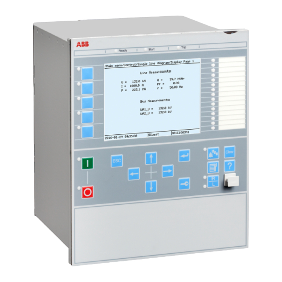
Page 69: Section 5 Local Hmi
AMU0600442 v15 IEC13000239-3-en.vsd IEC13000239 V3 EN-US Figure 22: Local human-machine interface The LHMI of the IED contains the following elements • Keypad • Display (LCD) • LED indicators • Communication port for PCM600 Busbar protection REB650 2.2 IEC Application manual... -
Page 70: Display
4 Scroll bar (appears when needed) The function key button panel shows on request what actions are possible with the function buttons. Each function button has a LED indication that can be used as a Busbar protection REB650 2.2 IEC Application manual... - Page 71 Each panel is shown by pressing one of the function buttons or the Multipage button. Pressing the ESC button clears the panel from the display. Both panels have a dynamic width that depends on the label string length. Busbar protection REB650 2.2 IEC Application manual...
-
Page 72: Leds
. These LEDs can indicate the status of two arbitrary binary signals by configuring the OPENCLOSE_LED function block. For instance, OPENCLOSE_LED can be connected to a circuit breaker to indicate the breaker open/close status on the LEDs. Busbar protection REB650 2.2 IEC Application manual... -
Page 73: Keypad
The push-buttons are also used to acknowledge alarms, reset indications, provide help and switch between local and remote control mode. The keypad also contains programmable push-buttons that can be configured either as menu shortcut or control buttons. Busbar protection REB650 2.2 IEC Application manual... - Page 74 Figure 27: LHMI keypad with object control, navigation and command push- buttons and RJ-45 communication port 1...5 Function button Close Open Escape Left Down Right Enter Remote/Local Uplink LED Not in use Multipage Menu Busbar protection REB650 2.2 IEC Application manual...
-
Page 75: Local Hmi Functionality
The blocking of functions through the IEC61850 protocol can be reset in Main menu/Test/Reset IEC61850 Mod. The yellow LED changes to either On or Off state depending on the state of operation. Busbar protection REB650 2.2 IEC Application manual... -
Page 76: Parameter Management
Numerical values are presented either in integer or in decimal format with minimum and maximum values. Character strings can be edited character by character. Enumerated values have a predefined set of selectable values. Busbar protection REB650 2.2 IEC Application manual... -
Page 77: Front Communication
Do not connect the IED front port to a LAN. Connect only a single local PC with PCM600 to the front port. It is only intended for temporary use, such as commissioning and testing. Busbar protection REB650 2.2 IEC Application manual... -
Page 79: Section 6 Differential Protection
Capacitor differential protection • Restricted earth fault protection for transformer, generator and shunt reactor windings • Restricted earth fault protection Three instances of HZPDIF are used as a busbar protection for one busbar zone. Busbar protection REB650 2.2 IEC Application manual... -
Page 80: The Basics Of The High Impedance Principle
The high impedance differential protection principle has been used for many years and is well documented in literature publicly available. Its operating principle provides very good sensitivity and high speed operation. One main benefit offered Busbar protection REB650 2.2 IEC Application manual... - Page 81 Metrosil IEC05000164-2-en.vsd IEC05000164 V3 EN-US Figure 31: Example for the high impedance restricted earth fault protection application Busbar protection REB650 2.2 IEC Application manual...
- Page 82 The tables 10, below show, the operating currents for different settings of operating voltages and selected resistances. Adjust as required based on tables 10, or to values in between as required for the application. Busbar protection REB650 2.2 IEC Application manual...
- Page 83 IP can be calculated. The IED sensitivity is decided by the total current in the circuit according to equation 12. å = × n IR Ires lmag (Equation 12) EQUATION1747 V1 EN-US Busbar protection REB650 2.2 IEC Application manual...
- Page 84 The series resistor is dimensioned for 200 W. Preferable the U>Trip SeriesResistor should always be lower than 200 W to allow continuous activation during testing. If this value is exceeded, testing should be done with a transient faults. Busbar protection REB650 2.2 IEC Application manual...
- Page 85 Rres I> Protected Object a) Through load situation b) Through fault situation c) Internal faults IEC05000427-2-en.vsd IEC05000427 V2 EN-US Figure 32: The high impedance principle for one phase with two current transformer inputs Busbar protection REB650 2.2 IEC Application manual...
-
Page 86: Connection Examples For High Impedance Differential Protection
3-Ph Plate with Metrosils and Resistors IEC07000193-5-en.vsdx IEC07000193 V5 EN-US Figure 33: CT connections for high impedance differential protection Description Scheme earthing point It is important to insure that only one earthing point exist in this scheme. Busbar protection REB650 2.2 IEC Application manual... -
Page 87: Connections For 1Ph High Impedance Differential Protection Hzpdif
G2AI2 ^GRP2L2 G2AI3 AI04 (I) ^GRP2L3 G2AI4 ^GRP2N AI05 (I) Protected Object AI06 (I) 1-Ph Plate with Metrosil and Resistor =IEC07000194=5=en=Original.vsdx IEC07000194 V5 EN-US Figure 34: CT connections for restricted earth fault protection Busbar protection REB650 2.2 IEC Application manual... -
Page 88: Setting Guidelines
Measure the value achieved and set this value for this parameter. The value shall always be high impedance. This means for example, for 1A circuits say bigger than 400 ohms (400 VA) and Busbar protection REB650 2.2 IEC Application manual... -
Page 89: T-Feeder Protection
T-zone is protected with a separate differential protection scheme. The 1Ph high impedance differential HZPDIF function in the IED allows this to be done efficiently, see Figure 35. Busbar protection REB650 2.2 IEC Application manual... - Page 90 Section 6 1MRK 505 388-UEN B Differential protection 3·Id IEC05000165-2-en.vsd IEC05000165 V2 EN-US 3·Id IEC05000739-2-en.vsd IEC05000739 V2 EN-US Figure 35: The protection scheme utilizing the high impedance function for the T-feeder Busbar protection REB650 2.2 IEC Application manual...
- Page 91 As this application requires to be so sensitive select SeriesResistor= 2000 ohm, which gives an IED operating current of 100 mA. Calculate the primary sensitivity at operating voltage using the following equation. Busbar protection REB650 2.2 IEC Application manual...
-
Page 92: Tertiary Reactor Protection
HZPDIF can be used to protect the tertiary reactor for phase faults as well as earth faults if the power system of the tertiary winding is direct or low impedance earthed. Busbar protection REB650 2.2 IEC Application manual... - Page 93 Busbar protection REB650 2.2 IEC Application manual...
- Page 94 For the voltage dependent resistor current the peak value of voltage 30 ˣ √2 is used. Then the RMS current is calculated by dividing obtained current value from the metrosil curve with √2. Use the maximum value from the metrosil curve given in Figure 37. Busbar protection REB650 2.2 IEC Application manual...
-
Page 95: Alarm Level Operation
The metrosil operating characteristic is given in the following figure. IEC05000749 V1 EN-US Figure 37: Current voltage characteristics for the non-linear resistors, in the range 10-200 V, the average range of current is: 0.01–10 mA Busbar protection REB650 2.2 IEC Application manual... -
Page 97: Section 7 Current Protection
If VT inputs are not available or not connected, the setting parameter DirModex (x = step 1, 2, 3 or 4) shall be left to the default value Non-directional. Busbar protection REB650 2.2 IEC Application manual... -
Page 98: Setting Guidelines
Thus, if only the inverse time delay is required, it is important to set the definite time delay for that stage to zero. Busbar protection REB650 2.2 IEC Application manual... - Page 99 7% of IB. 2ndHarmStab: Operate level of 2nd harmonic current restrain set in % of the fundamental current. The setting range is 5 - 100% in steps of 1%. The default setting is 20%. Busbar protection REB650 2.2 IEC Application manual...
-
Page 100: Settings For Each Step
DirModex: The directional mode of step x. Possible settings are Off/Non- directional/Forward/Reverse. Characteristx: Selection of time characteristic for step x. Definite time delay and different types of inverse time characteristics are available according to Table 12. Busbar protection REB650 2.2 IEC Application manual... - Page 101 ANSI reset characteristic according to standard. If IMinx is set above Ix> for any step the ANSI reset works as if current is zero when current drops below IMinx. Busbar protection REB650 2.2 IEC Application manual...
- Page 102 The delay characteristics are described in Technical manual. There are some restrictions regarding the choice of the reset delay. For the definite time delay characteristics, the possible delay time setting instantaneous (1) and IEC (2 = set constant time reset). Busbar protection REB650 2.2 IEC Application manual...
-
Page 103: Setting Example
The protection reset current must also be considered so that a short peak of overcurrent does not cause the operation of a protection even when the overcurrent has ceased. This phenomenon is described in Figure 40. Busbar protection REB650 2.2 IEC Application manual... - Page 104 The maximum load current on the line has to be estimated. There is also a demand that all faults within the zone that the protection shall cover must be detected by the phase overcurrent protection. The minimum fault current Iscmin to be detected by Busbar protection REB650 2.2 IEC Application manual...
- Page 105 This is mostly used in the case of inverse time overcurrent protection. Figure shows how the time-versus-current curves are plotted in a diagram. The time setting is chosen to get the shortest fault time with maintained selectivity. Busbar protection REB650 2.2 IEC Application manual...
- Page 106 These time delays can vary significantly between different protective equipment. The following time delays can be estimated: Protection operation 15-60 ms time: Protection resetting time: 15-60 ms Breaker opening time: 20-120 ms Busbar protection REB650 2.2 IEC Application manual...
- Page 107 There are uncertainties in the values of protection operation time, breaker opening time and protection resetting time. Therefore a safety margin has to be included. With normal values the needed time difference can be calculated according to Equation 24. Busbar protection REB650 2.2 IEC Application manual...
-
Page 108: Directional Residual Overcurrent Protection, Four Steps Ef4Ptoc
In many applications, several steps with different current operating levels and time delays are needed. EF4PTOC can have up to four, individual settable steps. The flexibility of each step of EF4PTOC is great. The following options are possible: Busbar protection REB650 2.2 IEC Application manual... - Page 109 ANSI Long Time Inverse IEC Normal Inverse IEC Very Inverse IEC Inverse IEC Extremely Inverse IEC Short Time Inverse IEC Long Time Inverse IEC Definite Time User Programmable ASEA RI RXIDG or RD (logarithmic) Busbar protection REB650 2.2 IEC Application manual...
-
Page 110: Setting Guidelines
SeqTypeUPol: This is used to select the type of voltage polarising quantity i.e. Zero seq or Neg seq for direction detection. SeqTypeIPol: This is used to select the type of current polarising quantity i.e. Zero seq or Neg seq for direction detection. Busbar protection REB650 2.2 IEC Application manual... -
Page 111: Common Settings For All Steps
In such cases the polarizing voltage (3U ) can be below 1% and it is then necessary to use current polarizing or dual polarizing. Multiply the required set current (primary) with the minimum impedance (ZNpol) and check that the Busbar protection REB650 2.2 IEC Application manual... -
Page 112: 2Nd Harmonic Restrain
In case of parallel transformers there is a risk of sympathetic inrush current. If one of the transformers is in operation, and the parallel transformer is switched in, the asymmetric inrush current of the switched-in transformer will cause partial Busbar protection REB650 2.2 IEC Application manual... -
Page 113: Switch Onto Fault Logic
This logic can be used to issue a fast trip if one breaker pole does not close properly at a manual or automatic closing. SOTF and under time are similar functions to achieve fast clearance at asymmetrical closing based on requirements from different utilities. Busbar protection REB650 2.2 IEC Application manual... -
Page 114: Settings For Each Step (X = 1, 2, 3 And 4)
In meshed networks, the settings must be based on network fault calculations. To assure selectivity between different protections, in the radial network, there has to be a minimum time difference Dt between the time delays of two protections. To Busbar protection REB650 2.2 IEC Application manual... - Page 115 Minimum operating time for inverse time characteristics. At high currents, the inverse time characteristic might give a very short operation time. By setting this parameter, the operation time of the step can never be shorter than the setting. Busbar protection REB650 2.2 IEC Application manual...
- Page 116 ÷ [ ] = × ç ÷ æ ö ç ÷ ç ÷ è > ø è ø (Equation 25) EQUATION1189 V1 EN-US Further description can be found in the technical reference manual. Busbar protection REB650 2.2 IEC Application manual...
-
Page 117: Four Step Directional Negative Phase Sequence Overcurrent Protection Ns4Ptoc
Non-directional/Directional function: In some applications the non-directional functionality is used. This is mostly the case when no fault current can be fed from the protected object itself. In order to achieve both selectivity and fast fault Busbar protection REB650 2.2 IEC Application manual... - Page 118 In some cases some sort of delayed reset is required. Therefore different kinds of reset characteristics can be used. Busbar protection REB650 2.2 IEC Application manual...
-
Page 119: Setting Guidelines
Characteristx: Selection of time characteristic for step x. Definite time delay and different types of inverse time characteristics are available. Table 16: Inverse time characteristics Curve name ANSI Extremely Inverse ANSI Very Inverse ANSI Normal Inverse Table continues on next page Busbar protection REB650 2.2 IEC Application manual... - Page 120 Minimum operation time for inverse time characteristics. At high currents the inverse time characteristic might give a very short operation time. By setting this parameter the operation time of the step can never be shorter than the setting. Busbar protection REB650 2.2 IEC Application manual...
- Page 121 ANSI (3 = current dependent reset time). If the current dependent type is used settings pr, tr and cr must be given. tPCrvx, tACrvx, tBCrvx, tCCrvx: Parameters for programmable inverse time characteristic curve. The time characteristic equation is according to equation 26: Busbar protection REB650 2.2 IEC Application manual...
-
Page 122: Common Settings For All Steps
1, 2, 3 and 4. AngleRCA: Relay characteristic angle given in degrees. This angle is defined as shown in figure 47. The angle is defined positive when the residual current lags the reference voltage (Upol = -U2) Busbar protection REB650 2.2 IEC Application manual... -
Page 123: Thermal Overload Protection, Two Time Constants Trpttr
% of IBase. The start forward or start reverse signals can be used in a communication scheme. The appropriate signal must be configured to the communication scheme block. Thermal overload protection, two time constants TRPTTR IP14513-1 v4 Busbar protection REB650 2.2 IEC Application manual... -
Page 124: Identification
The thermal overload protection estimates the internal heat content of the transformer (temperature) continuously. This estimation is made by using a thermal model of the transformer which is based on current measurement. Busbar protection REB650 2.2 IEC Application manual... -
Page 125: Setting Guideline
(FOA). If the transformer has no forced cooling IBase2 can be set equal to IBase1. Tau1: The thermal time constant of the protected transformer, related to IBase1 (no cooling) given in minutes. Busbar protection REB650 2.2 IEC Application manual... - Page 126 ILowTau2. ILowTau2 is set in % of IBase2. The possibility to change time constant with the current value as the base can be useful in different applications. Below some examples are given: Busbar protection REB650 2.2 IEC Application manual...
-
Page 127: Setting Example
= - × ç final operate ÷ ç ÷ operate è ø final (Equation 28) EQUATION1176 V1 EN-US where: is the time to operate operate is the time constant Table continues on next page Busbar protection REB650 2.2 IEC Application manual... - Page 128 For example, the largest phase load current is taken as 1800 A, then: 1800 2677685.95 final (1.2 1000 1.1 1.2) 2509056 operate Busbar protection REB650 2.2 IEC Application manual...
-
Page 129: Breaker Failure Protection Ccrbrf
Breaker failure protection CCRBRF IP14514-1 v6 7.5.1 Identification M14878-1 v5 Function description IEC 61850 IEC 60617 ANSI/IEEE C37.2 identification identification device number Breaker failure protection, 3-phase CCRBRF 50BF activation and output 3I>BF SYMBOL-U V1 EN-US Busbar protection REB650 2.2 IEC Application manual... -
Page 130: Application
CB Pos Check (circuit breaker position check) and Contact means re-trip is done when circuit breaker is closed (breaker position is used). No CBPos Check means re-trip is done without any check of breaker position. Busbar protection REB650 2.2 IEC Application manual... - Page 131 Also in effectively earthed systems the setting of the earth-fault current protection can be chosen to relatively low current level. The Busbar protection REB650 2.2 IEC Application manual...
- Page 132 It is often required that the total fault clearance time shall be less than a given critical time. This time is often dependent of the ability to maintain transient stability in case of a fault close to a power plant. Busbar protection REB650 2.2 IEC Application manual...
-
Page 133: Pole Discordance Protection Ccpdsc
Trip pulse duration. This setting must be larger than the critical impulse time of circuit breakers to be tripped from the breaker failure protection. Typical setting is 200 ms. Pole discordance protection CCPDSC IP14516-1 v5 Busbar protection REB650 2.2 IEC Application manual... -
Page 134: Identification
The following settings can be done for the pole discordance protection. GlobalBaseSel: Selects the global base value group used by the function to define IBase, UBase and SBase as applicable. Operation: Off or On Busbar protection REB650 2.2 IEC Application manual... - Page 135 This is due to the existence of low impedance current paths in the switch yard. This phenomenon must be considered in the setting of the parameter. CurrRelLevel: Current magnitude for release of the function in % of IBase. Busbar protection REB650 2.2 IEC Application manual...
-
Page 137: Section 8 Voltage Protection
Disconnect apparatuses, like electric motors, which will be damaged when subject to service under low voltage conditions. The function has a high measuring accuracy and a settable hysteresis to allow applications to control reactive load. Busbar protection REB650 2.2 IEC Application manual... -
Page 138: Setting Guidelines
8.1.3.5 Backup protection for power system faults M13851-62 v3 The setting must be below the lowest occurring "normal" voltage and above the highest occurring voltage during the fault conditions under consideration. Busbar protection REB650 2.2 IEC Application manual... -
Page 139: Settings For Two Step Undervoltage Protection
When using inverse time characteristic for the undervoltage function during very low voltages can give a short operation time. This might lead to unselective tripping. By setting t1Min longer than the operation time for other protections, such unselective tripping can be avoided. Busbar protection REB650 2.2 IEC Application manual... -
Page 140: Two Step Overvoltage Protection Ov2Ptov
Two step overvoltage protection OV2PTOV IP14545-1 v3 8.2.1 Identification M17002-1 v8 Function description IEC 61850 IEC 60617 identification ANSI/IEEE C37.2 identification device number Two step overvoltage protection OV2PTOV 3U> SYMBOL-C-2U-SMALLER-THAN V2 EN-US Busbar protection REB650 2.2 IEC Application manual... -
Page 141: Application
The same also applies to the associated equipment, its voltage and time characteristic. There are wide applications where general overvoltage functions are used. All voltage related settings are made as a percentage of a settable base primary voltage, Busbar protection REB650 2.2 IEC Application manual... -
Page 142: Equipment Protection, Such As For Motors, Generators, Reactors And Transformers
The following settings can be done for the two step overvoltage protection M13852-22 v10 ConnType: Sets whether the measurement shall be phase-to-earth fundamental value, phase-to-phase fundamental value, phase-to-earth RMS value or phase-to- phase RMS value. Busbar protection REB650 2.2 IEC Application manual... - Page 143 The speed might be important for example in case of protection of transformer that might be overexcited. The time delay must be co- ordinated with other automated actions in the system. Busbar protection REB650 2.2 IEC Application manual...
- Page 144 If the function is used as control for automatic switching of reactive compensation devices the hysteresis must be set smaller than the voltage change after switching of the compensation device. Busbar protection REB650 2.2 IEC Application manual...
-
Page 145: Two Step Residual Overvoltage Protection Rov2Ptov
The time delay for ROV2PTOV is seldom critical, since residual voltage is related to earth faults in a high-impedance earthed system, and enough time must normally be given for the primary protection to clear the fault. In some more specific Busbar protection REB650 2.2 IEC Application manual... -
Page 146: Equipment Protection, Such As For Motors, Generators, Reactors And Transformersequipment Protection For Transformers
The two healthy phases will measure full phase-to- phase voltage, as the faulty phase will be connected to earth. The residual overvoltage will be three times the phase-to-earth voltage. See figure 49. Busbar protection REB650 2.2 IEC Application manual... -
Page 147: Direct Earthed System
The other healthy phase will still have normal phase-to-earth voltage. The residual sum will have the same value as the remaining phase-to-earth voltage, which is shown in Figure 50. IEC07000189-2-en.vsd IEC07000189 V2 EN-US Figure 50: Earth fault in Direct earthed system Busbar protection REB650 2.2 IEC Application manual... -
Page 148: Settings For Two Step Residual Overvoltage Protection
The setting is highly dependent on the protection application. In many applications, the protection function has the task to prevent damage to the protected object. The speed might be important, for Busbar protection REB650 2.2 IEC Application manual... - Page 149 Make sure that the set value for parameter HystABSn is somewhat smaller than the set pickup value. Otherwise there is a risk that step n will not reset properly. Busbar protection REB650 2.2 IEC Application manual...
-
Page 151: Section 9 Secondary System Supervision
3U without the presence of the negative- sequence current 3I is a condition that is related to a fuse failure event. Busbar protection REB650 2.2 IEC Application manual... -
Page 152: Setting Guidelines
When the local breaker closes the current will start to flow and the function detects the fuse failure situation. But due to the 200 ms drop off timer the output BLKZ Busbar protection REB650 2.2 IEC Application manual... -
Page 153: Negative Sequence Based
(Equation 37) EQUATION1520 V5 EN-US where: is the maximal negative sequence current during normal operating conditions, plus a margin of 10...20% IBase GlobalBaseSel is the base current for the function according to the setting Busbar protection REB650 2.2 IEC Application manual... -
Page 154: Zero Sequence Based
DU> and DI< will prim be given according to equation and equation 41. USet prim > = UBase (Equation 40) EQUATION1523 V3 EN-US Busbar protection REB650 2.2 IEC Application manual... -
Page 155: Dead Line Detection
(mutual coupling to the other phases). Set the UDLD< with a sufficient margin below the minimum expected operating voltage. A safety margin of at least 15% is recommended. Busbar protection REB650 2.2 IEC Application manual... -
Page 157: Section 10 Control
The commands to an apparatus can be initiated from the Control Centre (CC), the station HMI or the local HMI on the IED front. Busbar protection REB650 2.2 IEC Application manual... - Page 158 The apparatus control function is realized by means of a number of function blocks designated: • Switch controller SCSWI • Circuit breaker SXCBR • Bay control QCBAY • Local remote LOCREM • Local remote control LOCREMCTRL Busbar protection REB650 2.2 IEC Application manual...
- Page 159 Figure 53. IEC 61850 -QB1 QCBAY SXCBR SCSWI SXCBR -QA1 SXCBR SCILO -QB9 IEC17000061=1=en=Orignal.ai IEC17000061 V1 EN-US Figure 52: Signal flow between apparatus control function blocks when all functions are situated within the IED Busbar protection REB650 2.2 IEC Application manual...
- Page 160 IED, then the local/remote switch is under authority control, otherwise the default user can perform control operations from the local IED HMI without logging in. The default position of the local/remote switch is on remote. Busbar protection REB650 2.2 IEC Application manual...
-
Page 161: Bay Control Qcbay
The Bay control (QCBAY) is used to handle the selection of the operator place per bay. The function gives permission to operate from two main types of locations either from Remote (for example, control centre or station HMI) or from Local Busbar protection REB650 2.2 IEC Application manual... -
Page 162: Switch Controller Scswi
SCSWI may handle and operate on one three-phase device or three one-phase switching devices. After the selection of an apparatus and before the execution, the switch controller performs the following checks and actions: Busbar protection REB650 2.2 IEC Application manual... -
Page 163: Switches Sxcbr
Substitution of position indication • Supervision timer that the primary device starts moving after a command • Supervision of allowed time for intermediate position • Definition of pulse duration for open/close command respectively Busbar protection REB650 2.2 IEC Application manual... -
Page 164: Proxy For Signals From Switching Device Via Goose Xlnproxy
XLNPROXY function, their usage is controlled by the connection of each data’s signal input and valid input. These connections are usually from the GOOSEXLNRCV function (see Figure and Figure 56). Busbar protection REB650 2.2 IEC Application manual... - Page 165 Section 10 1MRK 505 388-UEN B Control IEC16000071 V1 EN-US Figure 55: Configuration with XLNPROXY and GOOSEXLNRCV where all the IEC 61850 modelled data is used, including selection Busbar protection REB650 2.2 IEC Application manual...
- Page 166 SCSWI function. This cause is also shown on the output L_CAUSE as indicated in the following table: Busbar protection REB650 2.2 IEC Application manual...
-
Page 167: Interaction Between Modules
• The logical node Interlocking (SCILO) provides the information to SCSWI whether it is permitted to operate due to the switchyard topology. The Busbar protection REB650 2.2 IEC Application manual... - Page 168 (energizing-check) is included. • The Generic Automatic Process Control function, GAPC, handles generic commands from the operator to the system. The overview of the interaction between these functions is shown in Figure below. Busbar protection REB650 2.2 IEC Application manual...
-
Page 169: Setting Guidelines
Figure 57: Example overview of the interactions between functions in a typical 10.1.7 Setting guidelines M16669-3 v5 The setting parameters for the apparatus control function are set via the local HMI or PCM600. Busbar protection REB650 2.2 IEC Application manual... -
Page 170: Bay Control (Qcbay)
When the time has expired, the control function is reset, and a cause-code is given. tSynchrocheck is the allowed time for the synchrocheck function to fulfill the close conditions. When the time has expired, the function tries to start the synchronizing Busbar protection REB650 2.2 IEC Application manual... -
Page 171: Switch (Sxcbr)
If AdaptivePulse is set to Adaptive, it is the maximum length of the output pulse for an open command. The default length is set to 200 ms for a circuit breaker (SXCBR). Busbar protection REB650 2.2 IEC Application manual... -
Page 172: Proxy For Signals From Switching Device Via Goose Xlnproxy
Logic rotating switch for function selection and LHMI presentation SLGAPC SEMOD114936-1 v5 10.2.1 Identification SEMOD167845-2 v3 Function description IEC 61850 IEC 60617 ANSI/IEEE C37.2 identification identification device number Logic rotating switch for function SLGAPC selection and LHMI presentation Busbar protection REB650 2.2 IEC Application manual... -
Page 173: Application
Disabled, when pressing UP while on first position, the switch will jump to the last position; when pressing DOWN at the last position, the switch will jump to the first position; when set to Enabled, no jump will be allowed. Busbar protection REB650 2.2 IEC Application manual... -
Page 174: Selector Mini Switch Vsgapc
SA system as well. 10.3.3 Setting guidelines SEMOD158807-4 v4 Selector mini switch (VSGAPC) function can generate pulsed or steady commands (by setting the Mode parameter). When pulsed commands are generated, the length Busbar protection REB650 2.2 IEC Application manual... -
Page 175: Generic Communication Function For Double Point Indication Dpgapc
When the value of the input signal VALID changes, the timestamp of the output POSITION will be updated as the time when DPGAPC function detects the change. Refer to Table for the description of the input-output relationship in terms of the value and the quality attributes. Busbar protection REB650 2.2 IEC Application manual... -
Page 176: Setting Guidelines
ALL operator positions, the only functional position usable with the SPC8GAPC function block is REMOTE. 10.5.3 Setting guidelines SEMOD176518-4 v7 The parameters for the single point generic control 8 signals (SPC8GAPC) function are set via the local HMI or PCM600. Busbar protection REB650 2.2 IEC Application manual... -
Page 177: Automationbits, Command Function For Dnp3.0 Autobits
For description of the DNP3 protocol implementation, refer to the Communication manual. 10.6.3 Setting guidelines SEMOD158639-5 v3 AUTOBITS function block has one setting, (Operation: On/Off) enabling or disabling the function. These names will be seen in the DNP3 communication management tool in PCM600. Busbar protection REB650 2.2 IEC Application manual... -
Page 178: Single Command, 16 Signals Singlecmd
SINGLECMD Close CB1 CMDOUTy OUTy User- & defined conditions Synchro- check en04000206.vsd IEC04000206 V2 EN-US Figure 59: Application example showing a logic diagram for control of a circuit breaker via configuration logic circuits Busbar protection REB650 2.2 IEC Application manual... - Page 179 Configuration logic circuits SINGLESMD Device 1 CMDOUTy OUTy & User- defined conditions en04000208.vsd IEC04000208 V2 EN-US Figure 61: Application example showing a logic diagram for control of external devices via configuration logic circuits Busbar protection REB650 2.2 IEC Application manual...
-
Page 180: Setting Guidelines
0 to 1. That means the configured logic connected to the command function block may not have a cycle time longer than the cycle time for the command function block. Busbar protection REB650 2.2 IEC Application manual... -
Page 181: Section 11 Logic
In the event of a transient fault the slave breaker performs a three-phase reclosing onto the non-faulted line. The same philosophy can be used for two-phase tripping and autoreclosing. Busbar protection REB650 2.2 IEC Application manual... -
Page 182: Three-Phase Tripping
The single-phase tripping operation mode can include different options and the use of the different inputs in the function block. Inputs TRINL1, TRINL2 and TRINL3 Busbar protection REB650 2.2 IEC Application manual... - Page 183 OR conditions from both line protections. Other back-up functions are connected to the input TRIN as described above for three-phase tripping. A typical connection for a single-phase tripping scheme is shown in figure 63. Busbar protection REB650 2.2 IEC Application manual...
-
Page 184: Single-, Two- Or Three-Phase Tripping
The SMPPTRC function block is provided with possibilities to initiate lock-out. The lock-out can be set to only activate the block closing output CLLKOUT or initiate the block closing output and also maintain the trip signal output TR3P (latched trip). Busbar protection REB650 2.2 IEC Application manual... -
Page 185: Example Of Directional Data
SETLKOUT. 11.1.2.5 Example of directional data GUID-08AC09AB-2B2F-4095-B06E-1171CF225869 v2 An example how to connect the directional data from different application functions to the trip function is given below, see Figure 64: Busbar protection REB650 2.2 IEC Application manual... - Page 186 SMPPTRC, or directly to SMAGAPC and then to the SMPPTRC. The trip function (SMPPTRC) splits up the directional data as general output data for START, STL1, STL2, STL3, STN, FW and REV. Busbar protection REB650 2.2 IEC Application manual...
-
Page 187: Blocking Of The Function Block
Secures two- or three-pole tripping depending on Program selection during evolving faults. 11.2 Trip matrix logic TMAGAPC IP15121-1 v4 11.2.1 Identification SEMOD167882-2 v3 Function description IEC 61850 IEC 60617 ANSI/IEEE C37.2 identification identification device number Trip matrix logic TMAGAPC Busbar protection REB650 2.2 IEC Application manual... -
Page 188: Application
Group alarm logic function ALMCALH is used to route alarm signals to different LEDs and/or output contacts on the IED. ALMCALH output signal and the physical outputs allows the user to adapt the alarm signal to physical tripping outputs according to the specific application needs. Busbar protection REB650 2.2 IEC Application manual... -
Page 189: Setting Guidelines
LEDs and/or output contacts on the IED. INDCALH output signal IND and the physical outputs allows the user to adapt the indication signal to physical outputs according to the specific application needs. Busbar protection REB650 2.2 IEC Application manual... -
Page 190: Setting Guidelines
For each cycle time, the function block is given an serial execution number. This is shown when using the ACT configuration tool with the designation of the function block and the cycle time, see example below. Busbar protection REB650 2.2 IEC Application manual... -
Page 191: Fixed Signal Function Block Fxdsign
IED, either for forcing the unused inputs in other function blocks to a certain level/value, or for creating certain logic. Boolean, integer, floating point, string types of signals are available. One FXDSIGN function block is included in all IEDs. Busbar protection REB650 2.2 IEC Application manual... -
Page 192: Boolean 16 To Integer Conversion B16I
REFPDIF function inputs for normal transformer application 11.8 Boolean 16 to Integer conversion B16I SEMOD175715-1 v1 11.8.1 Identification SEMOD175721-2 v2 Function description IEC 61850 IEC 60617 ANSI/IEEE C37.2 identification identification device number Boolean 16 to integer conversion B16I Busbar protection REB650 2.2 IEC Application manual... -
Page 193: Application
The sum of the numbers in column “Value when activated” when all INx (where 1≤x≤16) are active that is=1; is 65535. 65535 is the highest boolean value that can be converted to an integer by the B16I function block. Busbar protection REB650 2.2 IEC Application manual... -
Page 194: Boolean To Integer Conversion With Logical Node
BOOLEAN Input 2 BOOLEAN Input 3 BOOLEAN Input 4 BOOLEAN Input 5 BOOLEAN Input 6 BOOLEAN Input 7 BOOLEAN Input 8 BOOLEAN Input 9 IN10 BOOLEAN Input 10 Table continues on next page Busbar protection REB650 2.2 IEC Application manual... -
Page 195: Integer To Boolean 16 Conversion Ib16
Values of each of the different OUTx from function block IB16 for 1≤x≤16. The sum of the value on each INx corresponds to the integer presented on the output OUT on the function block IB16. Busbar protection REB650 2.2 IEC Application manual... -
Page 196: Integer To Boolean 16 Conversion With Logic Node
(ITBGAPC) is used to transform an integer into a set of 16 boolean signals. ITBGAPC function can receive an integer from a station computer – for example, over IEC 61850–8–1. This function is very useful when the user wants to generate Busbar protection REB650 2.2 IEC Application manual... -
Page 197: Elapsed Time Integrator With Limit Transgression And Overflow Supervision Teigapc
ITBGAPC function block. 11.12 Elapsed time integrator with limit transgression and overflow supervision TEIGAPC 11.12.1 Identification GUID-1913E066-37D1-4689-9178-5B3C8B029815 v3 Function Description IEC 61850 IEC 60617 ANSI/IEEE C37.2 device identification identification number Elapsed time integrator TEIGAPC Busbar protection REB650 2.2 IEC Application manual... -
Page 198: Application
The limit for the overflow supervision is fixed at 999999.9 seconds. 11.13 Comparator for integer inputs - INTCOMP 11.13.1 Identification GUID-5992B0F2-FC1B-4838-9BAB-2D2542BB264D v1 Function description IEC 61850 IEC 60617 ANSI/IEEE C37.2 identification identification device number Comparison of integer values INTCOMP Int<=> Busbar protection REB650 2.2 IEC Application manual... -
Page 199: Application
Set the RefSource = Input REF Similarly for Signed comparison between inputs Set the EnaAbs = Signed Set the RefSource =Input REF For absolute comparison between input and setting Set the EnaAbs = Absolute Busbar protection REB650 2.2 IEC Application manual... -
Page 200: Comparator For Real Inputs - Realcomp
RefSource: This setting is used to select the reference source between input and setting for comparison. • Input REF: The function will take reference value from input REF • Set Value: The function will take reference value from setting SetValue Busbar protection REB650 2.2 IEC Application manual... -
Page 201: Setting Example
If the comparison should be done between two current magnitudes then those current signals need to be connected to function inputs, INPUT and REF. Then the settings should be adjusted as below, EnaAbs = Absolute RefSource = Input REF Busbar protection REB650 2.2 IEC Application manual... - Page 202 Section 11 1MRK 505 388-UEN B Logic EqualBandHigh = 5.0 % of reference value EqualBandLow = 5.0 % of reference value. Busbar protection REB650 2.2 IEC Application manual...
-
Page 203: Section 12 Monitoring
IEC 61850. The possibility to continuously monitor measured values of active power, reactive power, currents, voltages, frequency, power factor etc. is vital for efficient production, transmission and distribution of electrical energy. It Busbar protection REB650 2.2 IEC Application manual... - Page 204 (DFT values) of the measured current and voltage signals. The measured power quantities are available either, as instantaneously calculated quantities or, averaged values over a period of time (low pass filtered) depending on the selected settings. Busbar protection REB650 2.2 IEC Application manual...
-
Page 205: Zero Clamping
I leading U System mean voltage, calculated according to selected mode System mean current, calculated according to selected mode Frequency Relevant settings and their values on the local HMI under Main menu/ Settings/IED settings/Monitoring/Servicevalues(P_Q)/CVMMXN(P_Q): Busbar protection REB650 2.2 IEC Application manual... -
Page 206: Setting Guidelines
UAmpCompY: Amplitude compensation to calibrate voltage measurements at Y% of Ur, where Y is equal to 5, 30 or 100. IAmpCompY: Amplitude compensation to calibrate current measurements at Y% of Ir, where Y is equal to 5, 30 or 100. Busbar protection REB650 2.2 IEC Application manual... - Page 207 Integral deadband setting is the integral area, that is, measured value in m% of measuring range multiplied by the time between two measured values. XHiHiLim: High-high limit. Set as % of YBase (Y is SBase for S,P,Q UBase for Voltage measurement and IBase for current measurement). Busbar protection REB650 2.2 IEC Application manual...
- Page 208 The first phase will be used as reference channel and compared with the curve for calculation of factors. The factors will then be used for all related channels. IEC05000652 V2 EN-US Figure 68: Calibration curves Busbar protection REB650 2.2 IEC Application manual...
-
Page 209: Setting Examples
Set correctly CT and VT data and phase angle reference channel PhaseAngleRef using PCM600 for analog input channels Connect, in PCM600, measurement function to three-phase CT and VT inputs Set under General settings parameters for the Measurement function: Busbar protection REB650 2.2 IEC Application manual... - Page 210 Cycl: Report interval (s), Db: In 2000 Set ±Δdb=40 MW that is, 2% 0.001% of range, Int Db: In (larger changes than 40 MW will 0.001%s be reported) Table continues on next page Busbar protection REB650 2.2 IEC Application manual...
- Page 211 30% of Ir IAngComp100 Angle pre-calibration for current 0.00 at 100% of Ir Measurement function application for a power transformer SEMOD54481-61 v9 Single line diagram for this application is given in figure 70. Busbar protection REB650 2.2 IEC Application manual...
- Page 212 PCM600 for analog input channels Connect, in PCM600, measurement function to LV side CT & VT inputs Set the setting parameters for relevant Measurement function as shown in the following table 27: Busbar protection REB650 2.2 IEC Application manual...
-
Page 213: Gas Medium Supervision Ssimg
When the pressure becomes too low compared to the required value, the circuit breaker operation shall be blocked to minimize the risk of internal failure. Binary information based on the gas pressure in the circuit breaker is used as an Busbar protection REB650 2.2 IEC Application manual... -
Page 214: Setting Guidelines
This is used for the temperature lockout indication to reset after a set time delay in s. tResetTempAlm: This is used for the temperature alarm indication to reset after a set time delay in s. Busbar protection REB650 2.2 IEC Application manual... -
Page 215: Liquid Medium Supervision Ssiml
This is used to set the time delay for a level lockout indication, given in s. tTempAlarm: This is used to set the time delay for a temperature alarm indication, given in s. Busbar protection REB650 2.2 IEC Application manual... -
Page 216: Breaker Monitoring Sscbr
The breaker status is monitored using breaker auxiliary contacts. The breaker status is indicated by the binary outputs. These signals indicate whether the circuit breaker is in an open, closed or error state. Busbar protection REB650 2.2 IEC Application manual... - Page 217 10000/900 = 11 operations at the rated current. It is assumed that prior to tripping, the remaining life of a breaker is 10000 operations. Remaining life calculation for three different interrupted current conditions is explained below. Busbar protection REB650 2.2 IEC Application manual...
- Page 218 Binary input available from the pressure sensor is based on the pressure levels inside the arc chamber. When the pressure becomes too low compared to the required value, the circuit breaker operation is blocked. Busbar protection REB650 2.2 IEC Application manual...
-
Page 219: Setting Guidelines
CloseTimeCorr: Correction factor for circuit breaker closing travel time. tTrOpenAlm: Setting of alarm level for opening travel time. tTrCloseAlm: Setting of alarm level for closing travel time. OperAlmLevel: Alarm limit for number of mechanical operations. Busbar protection REB650 2.2 IEC Application manual... -
Page 220: Event Function Event
OperTimeDelay: Time delay between change of status of trip output and start of main contact separation. 12.5 Event function EVENT IP14590-1 v2 12.5.1 Identification SEMOD167950-2 v2 Function description IEC 61850 IEC 60617 ANSI/IEEE C37.2 identification identification device number Event function EVENT S00946 V1 EN-US Busbar protection REB650 2.2 IEC Application manual... -
Page 221: Application
0, that is, no cyclic communication. M12811-34 v1 It is important to set the time interval for cyclic events in an optimized way to minimize the load on the station bus. Busbar protection REB650 2.2 IEC Application manual... -
Page 222: Disturbance Report Drprdre
Thus, disturbance report is not dependent on the operation of protective functions, and it can record disturbances that were not discovered by protective functions for one reason or another. Disturbance report can be used as an advanced stand-alone disturbance recorder. Busbar protection REB650 2.2 IEC Application manual... -
Page 223: Setting Guidelines
Event list (EL), Event recorder (ER) and Indication (IND) uses information from the binary input function blocks (BxRBDR). Trip value recorder (TVR) uses analog information from the analog input function blocks (AxRADR). Disturbance report function acquires information from both AxRADR and BxRBDR. Busbar protection REB650 2.2 IEC Application manual... - Page 224 Trip) Flashing light The IED is in test mode Red LED: Steady light Triggered on binary signal N with SetLEDx = Trip (or Start and Trip) Flashing The IED is in configuration mode Busbar protection REB650 2.2 IEC Application manual...
-
Page 225: Recording Times
Prefault recording time (PreFaultRecT) is the recording time before the starting point of the disturbance. The setting should be at least 0.1 s to ensure enough samples for the estimation of pre-fault values in the Trip value recorder (TVR) function. Busbar protection REB650 2.2 IEC Application manual... -
Page 226: Binary Input Signals
(1) or negative (0) slope. OperationN: Disturbance report may trig for binary input N (On) or not (Off). TrigLevelN: Trig on positive (Trig on 1) or negative (Trig on 0) slope for binary input N. Busbar protection REB650 2.2 IEC Application manual... -
Page 227: Analog Input Signals
SetLEDN: Set red LED on local HMI in front of the IED if binary input N changes status. Disturbance recorder M12179-446 v5 OperationM: Analog channel M is to be recorded by the disturbance recorder (On) or not (Off). Busbar protection REB650 2.2 IEC Application manual... -
Page 228: Consideration
• Analog signals: The level triggering should be used with great care, since unfortunate settings will cause enormously number of recordings. If nevertheless analog input triggering is used, chose settings by a sufficient Busbar protection REB650 2.2 IEC Application manual... -
Page 229: Logical Signal Status Report Binstatrep
When an input is set, the respective output is set for a user defined time. If the input signal remains set for a longer period, the output will remain set until the input signal resets. INPUTn OUTPUTn IEC09000732-1-en.vsd IEC09000732 V1 EN-US Figure 73: BINSTATREP logical diagram Busbar protection REB650 2.2 IEC Application manual... -
Page 230: Setting Guidelines
In this case, periodic pulses will be generated at multiple overflow of the function. 12.8.3 Setting guidelines GUID-5AECCDBC-7385-4D9F-940C-9D4A0E59B106 v1 GUID-DA5DA8D7-4821-4BFB-86CC-28658E376270 v2 The parameters for Limit counter L4UFCNT are set via the local HMI or PCM600. Busbar protection REB650 2.2 IEC Application manual... -
Page 231: Running Hour-Meter Teilgapc
> tWarning. The limit for the overflow supervision is fixed at 99999.9 hours. The setting tAddToTime is a user settable time parameter in hours. Busbar protection REB650 2.2 IEC Application manual... -
Page 233: Section 13 Metering
M13396-4 v9 Parameters that can be set individually for each pulse counter from PCM600: • Operation: Off/On • tReporting: 0-3600s • EventMask: NoEvents/ReportEvents Configuration of inputs and outputs of PCFCNT is made via PCM600. Busbar protection REB650 2.2 IEC Application manual... -
Page 234: Function For Energy Calculation And Demand Handling Etpmmtr
(CVMMXN). This function has a site calibration possibility to further increase the total accuracy. The function is connected to the instantaneous outputs of (CVMMXN) as shown in figure 74. Busbar protection REB650 2.2 IEC Application manual... -
Page 235: Setting Guidelines
The following settings can be done for the energy calculation and demand handling function ETPMMTR: GlobalBaseSel: Selects the global base value group used by the function to define IBase, UBase and SBase as applicable. Operation: Off/On Busbar protection REB650 2.2 IEC Application manual... - Page 236 For the advanced user there are a number of settings for direction, zero clamping, max limit, and so on. Normally, the default values are suitable for these parameters. Busbar protection REB650 2.2 IEC Application manual...
-
Page 237: Section 14 Ethernet-Based Communication
When saving the ECT configuration after selecting a subnetwork, ECT creates the access point in the SCL model. Unselecting the subnetwork removes the access point from the SCL model. This column is editable for IEC61850 Ed2 IEDs and not editable for Busbar protection REB650 2.2 IEC Application manual... -
Page 238: Redundant Communication
Identification GUID-B7AE0374-0336-42B8-90AF-3AE1C79A4116 v1 Function description IEC 61850 IEC 60617 ANSI/IEEE C37.2 identification identification device number IEC 62439-3 Parallel redundancy protocol IEC 62439-3 High-availability seamless redundancy Access point diagnostic for redundant RCHLCCH Ethernet ports Busbar protection REB650 2.2 IEC Application manual... -
Page 239: Application
The redundant communication uses two Ethernet ports. Device 2 Device 1 PhyPortA PhyPortB PhyPortA PhyPortB Switch A Switch B PhyPortA PhyPortB PhyPortA PhyPortB Device 4 Device 3 IEC09000758-4-en.vsd IEC09000758 V4 EN-US Figure 75: Parallel Redundancy Protocol (PRP) Busbar protection REB650 2.2 IEC Application manual... -
Page 240: Setting Guidelines
PRP-1 and HSR can be combined in a mixed network. If the access point is not taken into operation, the write option in Ethernet Configuration Tool can be used to activate the access point. Busbar protection REB650 2.2 IEC Application manual... -
Page 241: Merging Unit
(or subscribers) in the system. Some merging units are able to get data from classical measuring transformers, others from non- conventional measuring transducers and yet others can pick up data from both types. Busbar protection REB650 2.2 IEC Application manual... -
Page 242: Setting Guidelines
Operation for the route can be set to On/Off by checking and unchecking the check-box in the operation column. Gateway specifies the address of the gateway. Destination specifies the destination. Destination subnet mask specifies the subnetwork mask of the destination. Busbar protection REB650 2.2 IEC Application manual... -
Page 243: Section 15 Station Communication
M13913-3 v6 Figure shows the topology of an IEC 61850–8–1 configuration. IEC 61850–8–1 specifies only the interface to the substation LAN. The LAN itself is left to the system integrator. Busbar protection REB650 2.2 IEC Application manual... - Page 244 SA system with IEC 61850–8–1 M16925-3 v4 Figure80 shows the GOOSE peer-to-peer communication. Station HSI MicroSCADA Gateway GOOSE Control Protection Control and protection Control Protection en05000734.vsd IEC05000734 V1 EN-US Figure 80: Example of a broadcasted GOOSE message Busbar protection REB650 2.2 IEC Application manual...
-
Page 245: Setting Guidelines
The settings available for Generic communication function for Measured Value (MVGAPC) function allows the user to choose a deadband and a zero deadband for the monitored signal. Values within the zero deadband are considered as zero. Busbar protection REB650 2.2 IEC Application manual... -
Page 246: Receiving Data
Input1 Input1 Ext_Res_OK_To_Operate DataValid Input2 Noput Input2 Noput CommValid Input3 Input3 Test Input4 Input4 IEC16000082=1=en.vsd IEC16000082 V1 EN-US Figure 81: GOOSESPRCV and AND function blocks - checking the validity of the received data Busbar protection REB650 2.2 IEC Application manual... -
Page 247: Iec/Uca 61850-9-2Le Communication Protocol
The process bus physical layout can be arranged in several ways, described in Annex B of the standard, depending on what are the needs for sampled data in a substation. Busbar protection REB650 2.2 IEC Application manual... - Page 248 The electronic part of a non-conventional measuring transducer (like a Rogowski coil or a capacitive divider) can represent a MU by itself as long as it can send sampled data over process bus. Busbar protection REB650 2.2 IEC Application manual...
-
Page 249: Setting Guidelines
Example of a station configuration with the IED receiving analog values from both classical measuring transformers and merging units. 15.3.2 Setting guidelines GUID-29B296B3-6185-459F-B06F-8E7F0C6C9460 v4 Merging Units (MUs) have several settings on local HMI under: Busbar protection REB650 2.2 IEC Application manual... -
Page 250: Specific Settings Related To The Iec/Uca 61850-9-2Le Communication
Loss of communication when used with LDCM GUID-29EFBCB7-2B4F-4AA1-B593-8E89838722E0 v4 If IEC/UCA 61850-9-2LE communication is lost, see examples in figures 84, and 86, the protection functions in table are blocked as per graceful degradation. Case 1: Busbar protection REB650 2.2 IEC Application manual... - Page 251 IEC13000299 V2 EN-US Figure 85: MU failed, mixed system Case 3: Failure of one MU (sample lost) blocks the sending and receiving of binary signals through LDCM. →DTT from the remote end is not working. Busbar protection REB650 2.2 IEC Application manual...
- Page 252 Four step residual EF4PTOC Sudden change in SCCVPTOC overcurrent protection current variation Instantaneous residual EFPIOC Sensitive Directional SDEPSDE overcurrent protection residual over current and power protetcion Table continues on next page Busbar protection REB650 2.2 IEC Application manual...
- Page 253 Negative sequence LCNSPTOV Scheme ZCPSCH overvoltage protection communication logic for distance or overcurrent protection Three phase LCP3PTOC Current reversal and ZCRWPSCH overcurrent weak-end infeed logic for distance protection Table continues on next page Busbar protection REB650 2.2 IEC Application manual...
- Page 254 Four step phase OC4PTOC Power swing detection ZMRPSB overcurrent protection Overexcitation OEXPVPH Mho Impedance ZSMGAPC protection supervision logic Out-of-step protection OOSPPAM Transformer tank TPPIOC overcurrent protection Table continues on next page Busbar protection REB650 2.2 IEC Application manual...
-
Page 255: Setting Examples For Iec/Uca 61850-9-2Le And Time Synchronization
When using an external clock, it is possible to set the IED to be synchronized via PPS,IRIG-B or PTP. It is also possible to use an internal GPS receiver in the IED (if the external clock is using GPS). Busbar protection REB650 2.2 IEC Application manual... - Page 256 SyncAccLevel: can be set to 1μs since this corresponds to a maximum phase angle error of 0.018 degrees at 50Hz Settings on the local HMI under Main menu/Configuration/Communication/ Ethernet configuration/Access point/AP_X: • Operation: On • PTP: On Busbar protection REB650 2.2 IEC Application manual...
- Page 257 Setting example when MU is the synchronizing source Settings on the local HMI under Main menu/Configuration/Time/ Synchronization/TIMESYNCHGEN:1/IEC61850-9-2: • HwSyncSrc: set to PPS as generated by the MU (ABB MU) • SyncLostMode : set to Block to block protection functions if time synchronization is lost •...
- Page 258 HWSyncSrc , “full-time” has to be acquired from another source. If station clock is on the local area network (LAN) and has an sntp-server, this is one option. Two status monitoring signals can be: Busbar protection REB650 2.2 IEC Application manual...
- Page 259 Synchronization/TIMESYNCHGEN:1/IEC61850-9-2: • HwSyncSrc: set to Off • SyncLostMode: set to No block to indicate that protection functions are not blocked • SyncAccLevel: set to unspecified Two status monitoring signals with no time synchronization: Busbar protection REB650 2.2 IEC Application manual...
-
Page 260: Iec 61850 Quality Expander Qualexp
IED. The function outputs are updated once every second and, therefore, do not reflect the quality bits in real time. Busbar protection REB650 2.2 IEC Application manual... -
Page 261: Lon Communication Protocol
Cable diameter 62.5/125 m 1 mm Max. cable length 1000 m 10 m Wavelength 820-900 nm 660 nm Transmitted power -13 dBm (HFBR-1414) -13 dBm (HFBR-1521) Receiver sensitivity -24 dBm (HFBR-2412) -20 dBm (HFBR-2521) Busbar protection REB650 2.2 IEC Application manual... -
Page 262: Multicmdrcv And Multicmdsnd
The communication speed of the LON bus is set to the default of 1.25 Mbit/s. This can be changed by LNT. 15.4.2 MULTICMDRCV and MULTICMDSND SEMOD119881-1 v3 Busbar protection REB650 2.2 IEC Application manual... -
Page 263: Identification
LAN (see Figure 93), and when using the rear optical Ethernet port, the only hardware required for a station monitoring system is: • Optical fibers from the IED to the utility substation LAN • PC connected to the utility office LAN Busbar protection REB650 2.2 IEC Application manual... -
Page 264: Setting Guidelines
When the communication protocol is selected, the IED is automatically restarted, and the port then operates as a SPA port. The SPA communication setting parameters are set on the local HMI under Main menu/Configuration/Communication/Station communication/SPA/SPA:1. Busbar protection REB650 2.2 IEC Application manual... - Page 265 Refer to technical data to determine the rated communication speed for the selected communication interfaces. The IED does not adapt its speed to the actual communication conditions because the communication speed is set on the local HMI. Busbar protection REB650 2.2 IEC Application manual...
-
Page 266: Iec 60870-5-103 Communication Protocol
The master must have software that can interpret the IEC 60870-5-103 communication messages. For detailed information about IEC 60870-5-103, refer to IEC 60870 standard part 5: Transmission Busbar protection REB650 2.2 IEC Application manual... -
Page 267: Design
Function block with pre-defined functions in control direction, I103CMD. This block includes the FUNCTION TYPE parameter, and the INFORMATION NUMBER parameter is defined for each output signal. • Function commands in control direction Busbar protection REB650 2.2 IEC Application manual... - Page 268 I103FLTPROT. This block includes the FUNCTION TYPE parameter, and the INFORMATION NUMBER parameter is defined for each input signal. This block is suitable for distance protection, line differential, transformer differential, over-current and earth-fault protection functions. • Autorecloser indications in monitor direction Busbar protection REB650 2.2 IEC Application manual...
-
Page 269: Settings
A1RADR to A4RADR. The eight first ones belong to the public range and the remaining ones to the private range. 15.6.2 Settings M17109-116 v1 Busbar protection REB650 2.2 IEC Application manual... -
Page 270: Settings For Rs485 And Optical Serial Communication
The protocol to activate on a physical port is selected under: Main menu/Configuration/Communication/Station Communication/Port configuration/ • RS485 port • RS485PROT:1 (off, DNP, IEC103) • SLM optical serial port • PROTOCOL:1 (off, DNP, IEC103, SPA) Busbar protection REB650 2.2 IEC Application manual... -
Page 271: Settings From Pcm600
ON_SET. In addition there is a setting on each event block for function type. Refer to description of the Main Function type set on the local HMI. Busbar protection REB650 2.2 IEC Application manual... - Page 272 DRA#-Input IEC 60870-5-103 meaning Private range Private range Private range Private range Private range Private range Private range Private range Private range Private range Private range Private range Table continues on next page Busbar protection REB650 2.2 IEC Application manual...
-
Page 273: Function And Information Types
Refer to the tables in the Technical reference manual /Station communication, specifying the information types supported by the communication protocol IEC 60870-5-103. To support the information, corresponding functions must be included in the protection IED. There is no representation for the following parts: Busbar protection REB650 2.2 IEC Application manual... -
Page 274: Dnp3 Communication Protocol
For more information, refer to IEC standard IEC 60870-5-103. 15.7 DNP3 Communication protocol 15.7.1 Application GUID-EF1F0C38-9FF6-4683-8B10-AAA372D42185 v1 For more information on the application and setting guidelines for the DNP3 communication protocol refer to the DNP3 Communication protocol manual. Busbar protection REB650 2.2 IEC Application manual... -
Page 275: Section 16 Security
Apart from the built-in supervision of the various modules, events are also generated when the status changes for the: • built-in real time clock (in operation/out of order). • external time synchronization (in operation/out of order). Busbar protection REB650 2.2 IEC Application manual... -
Page 276: Change Lock Chnglck
The binary input controlling the function is defined in ACT or SMT. The CHNGLCK function is configured using ACT. LOCK Binary input signal that will activate/deactivate the function, defined in ACT or SMT. Busbar protection REB650 2.2 IEC Application manual... -
Page 277: Denial Of Service Schlcch/Rchlcch
CHNGLCK input, that logic must be designed so that it cannot permanently issue a logical one to the CHNGLCK input. If such a situation would occur in spite of these precautions, then please contact the local ABB representative for remedial action. 16.4 Denial of service SCHLCCH/RCHLCCH 16.4.1... -
Page 279: Section 17 Basic Ied Functions
• ProductDef • FirmwareVer • SerialNo • OrderingNo • ProductionDate • IEDProdType Figure 96: IED summary This information is very helpful when interacting with ABB product support (for example during repair and maintenance). Busbar protection REB650 2.2 IEC Application manual... -
Page 280: Factory Defined Settings
• IEDMainFunType • Main function type code according to IEC 60870-5-103. Example: 128 (meaning line protection). • SerialNo • OrderingNo • ProductionDate 17.3 Measured value expander block RANGE_XP SEMOD52451-1 v2 Busbar protection REB650 2.2 IEC Application manual... -
Page 281: Identification
Six different groups of setting parameters are available in the IED. Any of them can be activated through the different programmable binary inputs by means of external or internal control signals. Busbar protection REB650 2.2 IEC Application manual... -
Page 282: Setting Guidelines
17.5.3 Setting guidelines M15292-3 v2 Set the system rated frequency. Refer to section "Signal matrix for analog inputs SMAI" for description on frequency tracking. 17.6 Summation block 3 phase 3PHSUM SEMOD55968-1 v2 Busbar protection REB650 2.2 IEC Application manual... -
Page 283: Application
Global base values GBASVAL 17.7.2 Application GUID-D58ECA9A-9771-443D-BF84-8EF582A346BF v4 Global base values function (GBASVAL) is used to provide global values, common for all applicable functions within the IED. One set of global values Busbar protection REB650 2.2 IEC Application manual... -
Page 284: Setting Guidelines
These names will define SMBI function in the Signal Matrix tool. The user defined name for the input or output signal will also appear on the respective output or input signal. 17.9 Signal matrix for binary outputs SMBO SEMOD55215-1 v2 Busbar protection REB650 2.2 IEC Application manual... -
Page 285: Application
Ph-Ph, the user is advised to connect two (not three) of the inputs GRPxL1, GRPxL2 and GRPxL3 to the same voltage input as shown in figure to make SMAI calculate a positive sequence voltage. Busbar protection REB650 2.2 IEC Application manual... -
Page 286: Setting Guidelines
Application functions should be connected to a SMAI block with same task cycle as the application function, except for e.g. measurement functions that run in slow cycle tasks. DFTRefExtOut: Parameter valid only for function block SMAI1 . Reference block for external output (SPFCOUT function output). Busbar protection REB650 2.2 IEC Application manual... - Page 287 (CVMMXN, CMMXU,VMMXU, etc.) which shall be fed by preprocessing blocks with cycle 8. When two or more preprocessing blocks are used to feed one protection function (e.g. over-power function GOPPDOP), it is of Busbar protection REB650 2.2 IEC Application manual...
- Page 288 In practice each instance can be adapted to the needs of the actual application. The adaptive frequency tracking is needed in IEDs that belong to the protection system of synchronous machines and that are active Busbar protection REB650 2.2 IEC Application manual...
- Page 289 SMAI1:13 – SMAI12:24: DFTReference = ExternalDFTRef to use DFTSPFC input of SMAI1:13 as reference (SMAI7:7) For task time group 3 this gives the following settings: SMAI1:25 – SMAI12:36: DFTReference = ExternalDFTRef to use DFTSPFC input as reference (SMAI7:7) Busbar protection REB650 2.2 IEC Application manual...
- Page 290 (see Figure 100) SMAI2:14 – SMAI12:24: DFTReference = DFTRefGrp4 to use SMAI4:16 as reference. For task time group 3 this gives the following settings: SMAI1:25 – SMAI12:36: DFTReference = ExternalDFTRef to use DFTSPFC input as reference (SMAI4:16) Busbar protection REB650 2.2 IEC Application manual...
-
Page 291: Test Mode Functionality Testmode
The supported values of the function block TESTMODE are described in Communication protocol manual, IEC 61850 Edition 2. When the function block TESTMODE is in test mode the Start LED on the LHMI is turned on with steady light. Busbar protection REB650 2.2 IEC Application manual... - Page 292 The block status of a component is shown on the LHMI as the Blk output under the same path as for Beh:Main menu/Test/Function status/Function group/Function block descriptive name/LN name/Outputs. If the Blk output is not shown, the component cannot be blocked. Busbar protection REB650 2.2 IEC Application manual...
-
Page 293: Setting Guidelines
The selection of the time source is done via the corresponding setting. If PTP is activated, the device with the best accuracy within the synchronizing group will be selected as the source. For more information about PTP, see the Technical manual. Busbar protection REB650 2.2 IEC Application manual... -
Page 294: Setting Guidelines
TimeSynch. The time synchronization source can also be set from PCM600. The setting alternatives are: FineSyncSource can have the following values: • • • • BIN (Binary Minute Pulse) • SNTP • IRIG-B • CoarseSyncSrc which can have the following values: Busbar protection REB650 2.2 IEC Application manual... - Page 295 The PTP VLAN tag does not need to be the same on all access points in one IED. It is possible to mix as long as they are the same for all devices on each subnet. Busbar protection REB650 2.2 IEC Application manual...
- Page 296 SAM600, and gets its synch from the GPS. Moreover, the REL and REC both acts as a boundary clock to provide synch to the SAM600. On all access points, the PTP parameter is “ON”. Busbar protection REB650 2.2 IEC Application manual...
-
Page 297: Process Bus Iec/Uca 61850-9-2Le Synchronization
HwSyncSrc is not used and other means to synchronize the merging unit to the IED is required. For instance, FineSyncSource is set to the same source that the merging unit uses. Busbar protection REB650 2.2 IEC Application manual... -
Page 299: Section 18 Requirements
). As the present CT standards have no limitation of the level of remanent flux, these CTs are also classified as for example, class TPX, P and PX according to IEC. The IEC TR 61869-100, Edition Busbar protection REB650 2.2 IEC Application manual... - Page 300 So far remanence factors of maximum 80% have been considered when CT requirements have been decided for ABB IEDs. Even in the future this level of remanent flux probably will be the maximum level that will be considered when decided the CT requirements.
-
Page 301: Conditions
VHR type CTs (i.e. with new material) to be used together with ABB protection IEDs. However, this may result in unacceptably big CT cores, which can be difficult to manufacture and fit in available space. -
Page 302: Fault Current
Even in a case where the phase- to-earth fault current is smaller than the three-phase fault current the phase-to-earth fault can be dimensioning for the CT depending on the higher burden. Busbar protection REB650 2.2 IEC Application manual... -
Page 303: General Current Transformer Requirements
CT (TPZ) is not well defined as far as the phase angle error is concerned. If no explicit recommendation is given for a specific function we therefore recommend contacting ABB to confirm that the non remanence type can be used. -
Page 304: Non-Directional Instantaneous And Definitive Time, Phase And Residual Overcurrent Protection
The resistance of a single secondary wire should be used for faults in high impedance earthed systems. The burden of an IED current input channel (VA). S =0.020 VA/channel for I =1 A and =0.150 VA/channel for I =5 A Busbar protection REB650 2.2 IEC Application manual... -
Page 305: Non-Directional Inverse Time Delayed Phase And Residual Overcurrent Protection
æ ö ³ × × ç ÷ alreq max k max è ø (Equation 45) EQUATION1077 V2 EN-US where Maximum primary fundamental frequency current for close-in faults (A) kmax Busbar protection REB650 2.2 IEC Application manual... -
Page 306: Current Transformer Requirements For Cts According To
CT will deliver to a standard burden at ANSI 20 times rated secondary current without exceeding 10 % ratio correction. There are a number of standardized U values for example, U is 400 V for a C400 ANSI ANSI Busbar protection REB650 2.2 IEC Application manual... -
Page 307: Voltage Transformer Requirements
The ferro-resonance requirements of the CVTs are specified in chapter 6.502 of the standard. The transient responses for three different standard transient response classes, T1, T2 and T3 are specified in chapter 6.503 of the standard. CVTs according to all classes can be used. Busbar protection REB650 2.2 IEC Application manual... -
Page 308: Sntp Server Requirements
“type2”. The IED can receive data rates of 80 samples/cycle. Note that the IEC/UCA 61850-9-2LE standard does not specify the quality of the sampled values, only the transportation. Thus, the accuracy of the current and Busbar protection REB650 2.2 IEC Application manual... - Page 309 In principle the accuracy of the current and voltage transformers, together with the merging unit, shall have the same quality as direct input of currents and voltages. Busbar protection REB650 2.2 IEC Application manual...
-
Page 311: Section 19 Glossary
Binary signal transfer function, receiver blocks Binary signal transfer function, transmit blocks C37.94 IEEE/ANSI protocol used when sending binary signals between IEDs Controller Area Network. ISO standard (ISO 11898) for serial communication Circuit breaker Combined backplane module Busbar protection REB650 2.2 IEC Application manual... - Page 312 Delayed autoreclosing DARPA Defense Advanced Research Projects Agency (The US developer of the TCP/IP protocol etc.) DBDL Dead bus dead line DBLL Dead bus live line Direct current Data flow control Discrete Fourier transform Busbar protection REB650 2.2 IEC Application manual...
- Page 313 File Transfer Protocol Function type G.703 Electrical and functional description for digital lines used by local telephone companies. Can be transported over balanced and unbalanced lines Communication interface module with carrier of GPS receiver module Busbar protection REB650 2.2 IEC Application manual...
- Page 314 Common Mezzanine Card) standard for the mechanics and the PCI specifications from the PCI SIG (Special Interest Group) for the electrical EMF (Electromotive force). IEEE 1686 Standard for Substation Intelligent Electronic Devices (IEDs) Cyber Security Capabilities Intelligent electronic device Busbar protection REB650 2.2 IEC Application manual...
- Page 315 Light-emitting diode LON network tool Local operating network Miniature circuit breaker Mezzanine carrier module Main processing module MVAL Value of measurement Multifunction vehicle bus. Standardized serial bus originally developed for use in trains. Busbar protection REB650 2.2 IEC Application manual...
- Page 316 Precision time protocol PT ratio Potential transformer or voltage transformer ratio PUTT Permissive underreach transfer trip RASC Synchrocheck relay, COMBIFLEX Relay characteristic angle RISC Reduced instruction set computer RMS value Root mean square value Busbar protection REB650 2.2 IEC Application manual...
- Page 317 Strömberg Protection Acquisition (SPA), a serial master/ slave protocol for point-to-point and ring communication. Switch for CB ready condition Switch or push button to trip Starpoint Neutral point of transformer or generator Static VAr compensation Trip coil Busbar protection REB650 2.2 IEC Application manual...
- Page 318 (23.5 degrees), but still showing the Earth's irregular rotation, on which UT1 is based. The Coordinated Universal Time is expressed using a 24-hour clock, and uses the Gregorian calendar. It is used for Busbar protection REB650 2.2 IEC Application manual...
- Page 319 Voltage transformer Three times zero-sequence current.Often referred to as the residual or the earth-fault current Three times the zero sequence voltage. Often referred to as the residual voltage or the neutral point voltage Busbar protection REB650 2.2 IEC Application manual...
- Page 322 — ABB AB Grid Automation Products 721 59 Västerås, Sweden Phone: +46 (0) 21 32 50 00 abb.com/protection-control © Copyright 2017 ABB. All rights reserved. Specifications subject to change without notice.
Need help?
Do you have a question about the REB650 and is the answer not in the manual?
Questions and answers