Table of Contents
Advertisement
Advertisement
Table of Contents

Subscribe to Our Youtube Channel
Related Manuals for Inspur NF5288M5

Summary of Contents for Inspur NF5288M5
- Page 1 Inspur Yitian Supercomputer User Manual NF5288M5...
- Page 2 Inspur. The information in this manual is subject to change without notice. Inspur is the registered trademark of Inspur. All the other trademarks or registered trademarks mentioned in this manual are the property of their respective holders.
-
Page 3: Target Audience
Please install the product-compatible operating system and use the driver provided by Inspur. If you use an incompatible operating system or non-Inspur driver , it may cause compatibility issues and affect the normal use of the product, Inspur will not assume any responsibility or liability. -
Page 4: Table Of Contents
Contents 1 Safety Instructions ......................... 1 2 Product Specification ........................6 2.1 Introduction ..........................6 2.2 Features and Specifications ......................7 3 Component Identification ......................9 3.1 Front Panel Components ......................9 3.2 Rear Panel Components ......................10 3.3 Motherboard Components......................11 4 Operations ............................. - Page 5 6.3 Memory Option .......................... 26 6.4 Hot-plug HDD Option ......................... 28 6.5 Redundant Hot-plug Power Supply Option ................29 6.6 Expansion Board Option ......................30 6.7 M.2 Memory Card Option ......................32 6.8 Air Baffle Option ......................... 33 6.9 Cache Supercapacitor Option ..................... 34 7 BIOS Setup .............................
- Page 6 11.1 Chinese Notice.......................... 105 11.2 Battery Replacement Notice ....................105 12 Electrostatic Discharge ........................ 106 12.1 Preventing Electrostatic Discharge ................... 106 12.2 Grounding Methods to Prevent Electrostatic Discharge ............106 13 Warranty ............................107 13.1 Introduction ..........................107 13.2 Warranty Service ........................107 13.3 Warranty Exclusions .........................
-
Page 7: Safety Instructions
For your safety, please do not attempt to remove the cover of the system to remove or replace any component without assistance provided by Inspur. Only service technicians trained by Inspur are authorized to remove the cover of the host, and to remove and replace internal components. - Page 8 The following considerations may help avoid the occurrence of problems that could damage the components or cause data loss, etc. In the event of the following, please unplug the power line plug from the power socket and contact Inspur’s customer service department:...
- Page 9 Close the host cover, reconnect the system to the power socket, and then power on. In case of operation failure or other abnormal situations, please contact Inspur and get technical support.
- Page 10 Upon receiving the proper authorization from Inspur and dismounting the internal components, please pay attention to the following: Switch the system power supply off and disconnect the cables, including all connections of the system.
- Page 11 Safety Introduction Ensure that components in the rack have good ventilation conditions. When repairing components in the rack, never step on any other components.
-
Page 12: Product Specification
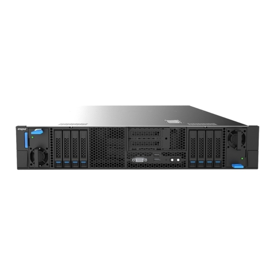
2 Product Specification 2.1 Introduction Inspur Yitian NF5288M5 (AGX-2) is a high-end, dual-socket and rack-mounted server, which is designed based on the new generation of Intel® Xeon® scalable processor, to satisfy the requirements of cloud computing, big data, data mining, deep learning and other high-end IT applications. -
Page 13: Features And Specifications
Product Specification the figure below. 2.2 Features and Specifications Processor Processor Type Intel® Skylake (supports up to two 165W processors) Socket Chipset Chipset Type LBG-4 Memory Memory Type DDR4 Registered, LR DIMM, NVDIMM, Apache Pass Memory Slot Qty. Total Memory Capacity Supports up to 1024GB (64GB per memory) 2 rear USB 3.0 ports, 2 front USB 3.0 ports 1 front VGA port 1 rear VGA port... - Page 14 Management It integrates 1 independent 1000Mbps network interface, special for IPMI remote Management Chip management. • PCIE configuration 1 onboard PCIe3.0 X8 RAID Mezz expander The front IO supports 2 PCIe3.0 X16 HHHL PCIe cards PCI Extension Slot • SXM2 full configuration 1 onboard PCIe3.0 X8 RAID Mezz expander The front IO supports 2 PCIe3.0 X16 HHHL PCIe cards The rear IO supports 4 PCIe3.0 X16 HHHL PCIe cards...
-
Page 15: Component Identification
Component Identification 3 Component Identification 3.1 Front Panel Components Item Description PSU0 2.5” HDD module PCIE slot (CPU0/SW11) PCIE slot (CPU1) 2.5” HDD module PUS1 Quick release lever Front VGA port Front USB3.0 ports (2) RST button & fault LED Power button &... -
Page 16: Rear Panel Components
● NVME HDD sequence diagram ● HDD Bay LEDs Item Description Status & Interpretation Steady red: An HDD failure occurs Fault alarm LED Steady blue: HDD positioning Steady blue: RAID rebuilding Steady green: Normal Activity status LED Flashing green: Read and write activity 3.2 Rear Panel Components Item Description... -
Page 17: Motherboard Components
Component Identification 3.3 Motherboard Components Item Description USB3.0 ports (2) RST button Power button UID button M.2 Riser slot PCIE Riser slot BMC_TF slot SAS/SATA connector 0 DIMM slots (CPU1) PSU1 control connector CPU1 PCIEx16_CPU0 SlimSAS connector 1 PCIEx16_CPU0 SlimSAS connector 2 CPU0... - Page 18 Item Description PSU0 control connector Fan board power connector Fan board control connector Rear IO Board connector 1 DIMM slots (CPU0) SAS/SATA connector 1 CLR_CMOS Rear IO Board connector 0 RAID KEY XDP connector TPM/TCM CPLD programming interface VGA port RAID Card connectors ●...
-
Page 19: Operations
Operations 4 Operations 4.1 Power up the Server Insert the power cord plug, then press the Power Button. 4.2 Power down the Server WARNING: To reduce the risk of personal injury, electric shock, or damage to the equipment, remove the power cord to remove power from the server. The front panel Power Button does not completely shut off system power. -
Page 20: Remove The Access Panel
After performing the installation or maintenance procedure, slide the server back into the rack until it clicks into place. Tighten the screws inside the two ears to secure the chassis in place. WARNING: To reduce the risk of personal injury, be careful when sliding the server into the rack. - Page 21 Operations CAUTION: For proper cooling, do not operate the server without the access panel, air baffle, or fan installed. If the server supports hot-plug components, minimize the amount of time the access panel is open. To remove the component: Power down the server if performing a non-hot-plug installation or maintenance procedure.
-
Page 22: Install The Access Panel
4.5 Install the Access Panel Place the rear access panel on the server. Align the guide pins on both sides with the corresponding guide slots on the chassis base. Push the rear access panel to the closed position and tighten the two screws clockwise. Open the hood latch, place the front access panel on the server, and align the guide pins on both sides with the corresponding guide slots on the chassis base. -
Page 23: Install The Pcie Riser Cage
Operations Hold the PCIE Riser cage and remove it vertically. 4.7 Install the PCIE Riser Cage Power down the server. Extend the server from the rack. Remove the front access panel. Install the PCIE Riser cage. If the PCIE Riser card is equipped with cables, connect the cables. Install the front access panel. - Page 24 Remove the access panel. If there are cables under the air baffle, pull them out. Remove the air baffle.
-
Page 25: Setup
● another rack or row of racks. Inspur Servers draw in cool air through the front door and expel warm air through the rear door. Therefore, the front and rear rack doors must be adequately ventilated to allow ambient room air to enter the cabinet, and the rear door must be adequately ventilated to allow the warm air to escape from the cabinet. - Page 26 Front and rear doors—If the 42U rack includes closing front and rear doors, you must ● allow 5,350 sq cm (830 sq in) of holes evenly distributed from top to bottom to permit adequate airflow (equivalent to the required 64 percent open area for ventilation). Side—The clearance between the installed rack component and the side panels of the ●...
- Page 27 Because of the high ground-leakage currents associated with multiple servers connected to the same power source, Inspur recommends the use of a PDU that is either permanently wired to the building’s branch circuit or includes a nondetachable cord that is wired to an industrial-style plug.
-
Page 28: Rack Warnings
5.2 Rack Warnings WARNING: To reduce the risk of personal injury or damage to the equipment, please be sure of the following: • The leveling jacks are extended to the floor. • The full weight of the rack rests on the leveling jacks. •... -
Page 29: Installing The Server Into The Rack
5.6 Installing the Operating System To operate properly, the server must have a supported operating system installed. For the latest information on supported operating systems, refer to the Inspur website (http://www. inspur.com/eportal/ui?pageId=2317460). To install the operating system on the server, you can download from the official website directly. -
Page 30: Hardware Options Installation
6 Hardware Options Installation 6.1 Introduction If more than one option is being installed, read the installation instructions for all the hardware options and identify similar steps to streamline the installation process. WARNING: To reduce the risk of personal injury from hot surfaces, allow the drives and the internal system components to cool before touching them. - Page 31 Hardware Options Installation Step 1: Align the Clip’s triangle mark with the CPU’s corner mark, and then assemble the Clip and CPU together. Step 2: Align the heatsink position marked by “1” with the Clip’s triangle mark, vertically align the mounting holes on the heatsink with those on the Clip, and assemble the heatsink and Clip together.
-
Page 32: Memory Option
Step 3: Install the assembled heatsink module onto the CPU socket, and the position marked by “1” should be aligned with the triangle mark on the CPU socket. Tighten the screws according to the sequence of 1, 2, 3, 4. Notes: ●... - Page 33 Hardware Options Installation ● DIMM population guidelines: Only DIMMs of the same type could be used in the same machine. Detailed DIMM population and combination principles are as follows: The white slots take the priority, while CPU1 DIMM shall be symmetrically installed with CPU0 DIMM.
-
Page 34: Hot-Plug Hdd Option
6.4 Hot-plug HDD Option CAUTION: For proper cooling, do not operate the server without the access panel, baffles, expansion slot covers, or blanks installed. If the server supports hot-plug components, minimize the amount of time the access panel is open. Check the status of the hard disk drive from the hot-plug HDD LED. -
Page 35: Redundant Hot-Plug Power Supply Option
Hardware Options Installation Step 4: Install the HDD into the chassis, and lock the lever firmly. 6.5 Redundant Hot-plug Power Supply Option CAUTION: To prevent improper cooling and thermal damage, do not operate the server unless all bays are populated with either a component or a blank. Access the product rear panel. -
Page 36: Expansion Board Option
Connect the power cord to the power supply. Route the power cord through the power cord anchor or cable management arm. Reposition the cable management arm into the operating position. Connect the power cord to the power source. Verify that the corresponding power supply LED is green. 6.6 Expansion Board Option CAUTION: To prevent damage to the server or expansion boards, power down the server... - Page 37 Hardware Options Installation Hold the PCIE Riser cage and remove it vertically. Remove the two retaining screws and remove the IO fixing plate.
-
Page 38: Memory Card Option
Pull out the expansion board in the direction of arrow to replace it with a new expansion board. 6.7 M.2 Memory Card Option CAUTION: To prevent damage to the server or expansion boards, power down the server and remove all AC power cords before removing or installing the PCIE Riser cage. CAUTION: For proper cooling, do not operate the server without the access panel, baffles, expansion slot covers, or blanks installed. -
Page 39: Air Baffle Option
Hardware Options Installation 6.8 Air Baffle Option CAUTION: For proper cooling, do not operate the server without the access panel, baffles, expansion slot covers, or blanks installed. If the server supports hot-plug components, minimize the amount of time the access panel is open. Power down the server. -
Page 40: Cache Supercapacitor Option
6.9 Cache Supercapacitor Option CAUTION: For proper cooling, do not operate the server without the access panel, baffles, expansion slot covers, or blanks installed. If the server supports hot-plug components, minimize the amount of time the access panel is open. Power down the server. -
Page 41: Bios Setup
Power on the server. The system will then start to boot. When the following content appears below Inspur logo on the screen: “Press<ESC> to Front Page Press<DEL> to Setup or <F11> to Boot Menu or <F12> to PXE Boot.” Press DEL key. When “Entering Setup …” appears in the lower right corner of the screen, it will enter the BIOS setup soon. -
Page 42: Bios Parameter Description
Note: Options in grey are not available. Options with symbol “ ” have a sub-menu. 7.2 BIOS Parameter Description 7.2.1 Front Page When Inspur Logo appears during system boot, press ESC to enter the Setup Front Page interface, as shown in the following figure:... - Page 43 BIOS Setup Front Page Interface Instruction Table Interface Parameters Function Description Default Value Product Name Display the current product name BIOS Version Display BIOS version CPU Type Display CPU type CPU Frequency Display CPU nominal frequency Memory Size Display the current system memory size Continue Continue to boot option Boot Manger...
- Page 44 Main Interface Instruction Table Interface Parameters Function Description Product Name Display current product name Serial Number Display product serial number Customer ID Display the customer ID BIOS Version Display the BIOS version Build Date Display the build date for current BIOS Version Build Time Display the build time for current BIOS Version BMC Firmware Version...
-
Page 45: Advanced Menu
BIOS Setup 7.2.3 Advanced Menu Advanced interface includes the BIOS system parameters and related function settings, as shown in the follow figure and table. Advanced Interface Instruction Table Interface Parameters Function Description Peripheral Configuration Peripheral devices configuration sub-menu Video Configuration Video configuration sub-menu Socket Configuration Socket configuration sub-menu... -
Page 46: Video Configuration
Peripheral Configuration Interface Instruction Table Interface Parameters Function Description Default Value PCIe SR-IOV PCIe device SR-IOV setting Enabled PCIe ARI ARI capability setting Disabled ARI Forward ARI forward setting Disabled 7.2.3.2 Video Configuration Video Configuration interface is used to set the system display mode, as shown in the following figure and table. -
Page 47: Processor Configuration
BIOS Setup Video Configuration Interface Instruction Table Interface Parameters Function Description Default Value Display Mode Set display mode configure type Plug In First 7.2.3.3 Socket Configuration Socket Configuration interface is used for system processor and memory related settings, as shown in the following figure and table. Socket Configuration Interface Instruction Table Interface Parameters Function Description... - Page 48 Processor Configuration Interface Instruction Table Default Value Interface Parameters Function Description Per-Socket Configuration Per-Socket setting sub-menu Per-Socket Information Per-Socket information display sub-menu Enabled Hype-Threading [ALL] Logical processor thread setting Enabled Execute Disable Bit Virus protecting technology setting Disabled Enable Intel(R) TXT Intel trustable execution technology setting Enabled Intel hardware-assisted virtualization technology settings...
- Page 49 BIOS Setup CPU Socket Configuration Interface Instruction Table Interface Parameters Function Description Default Value Available Core Bitmap(Hex) Display the available core bitmap Core Disable Bitmap(Hex) Disabled core bitmap setting Enable Core Bitmap(Hex) Display the enable core bitmap Desired Core Count Display the number of enabled cores Information of all processors will be displayed by entering Per-Socket Information sub menu.
- Page 50 7.2.3.3.2 Common RefCode Configuration Common RefCode Configuration interface is used for common settings, as shown in the following figure and table. Common RefCode Configuration Interface Introduction Interface Parameters Function Description Default Value Chose socket to output serial message MRC serial message display setting Socket0 MMIO High Granularity Size MMIO high resources granularity size setting 256G...
- Page 51 BIOS Setup 7.2.3.3.3 UPI Configuration UPI Configuration interface is used for UPI related settings, as shown in the following figure and table. UPI Configuration Interface Instruction Table Interface Parameters Function Description UPI General Configuration UPI general configuration sub-menu UPI Per Socket Configuration UPI per-socket configuration sub-menu It will display UPI general configuration menu by entering UPI General Configuration sub menu.
-
Page 52: Memory Configuration
UPI General Configuration Interface Instruction Table Default Value Interface Parameters Function Description UPI Status UPI status display sub-menu Auto Link Frequency Select UPI link frequency setting UPI link power saving mode settings, which is made Auto Link L0p Enable when bandwidth is half of the peak bandwidth. In the case that system is extremely idle, turn off QPI Auto Link L1 Enable... - Page 53 BIOS Setup Memory Configuration Interface Instruction Table Interface Parameters Function Description Default Value Enforce POR Enforce POR settings Auto Memory Configuration Memory frequency select setting Auto Rank Margin Tool Rank margin tool setting Disabled Set the pattern length for the rank margin tool when RMT Pattern Length 32767 it’s enabled...
- Page 54 It will display the memory RAS configuration by entering the Memory RAS Configuration sub menu. Memory RAS Configuration Interface Instruction Table Interface Parameters Function Description Default Value Operation RAS mode Display current operation RAS mode Operation ext RAS mode Display current operation extra RAS mode Support RAS mode Display supported RAS mode Support ext RAS mode...
- Page 55 BIOS Setup IIO Configuration Interface Instruction Table Interface Parameters Function Description Default Value Socket# Configuration Socket# IIO Configuration setting sub-menu Intel VT for Directed I/O (VT-d) Intel VT-d switching setting sub-menu PCI 64-Bit Resource Allocation PCI 64-bit resource allocation setting Enabled PCI-E ASPM Support (Global) Global PCIe device ASPM support setting...
- Page 56 Advanced Power Management Configuration Interface Instruction Table Interface Parameters Function Description CPU P State Control CPU P state control configuration sub-menu CPU C State Control CPU C state control configuration sub-menu Package C State Control Package C state setting sub-menu CPU-Advanced PM Tuning CPU advanced PM turning setting sub-menu It will display the CPU P state configuration menu by entering CPU P State Control sub...
- Page 57 BIOS Setup CPU C State Control Interface Instruction Table Default Value Interface Parameters Function Description Disabled CPU C6 report Report C6 state to OS setting It will display the package C state configuration menu by entering Package C State Control sub menu.
- Page 58 Select CPU Advanced PM Tuning menu, select Energy Perf BIAS, and enter power performance setting interface, as shown below: Energy Perf BIAS Interface Instruction Table Interface Parameters Function Description Default Value Power Performance Tuning Power performance tuning setting OS Controls EPB Balanced ENERGY_PERF_BIAS_CFG mode Performance setting...
- Page 59 BIOS Setup The general information of ME configuration will be displayed by entering Server ME Configuration sub menu. Sever ME Configuration Interface Instruction Table nterface Parameters Function Description ME-BIOS Interface Ver. ME BIOS interface version ME SKU ME SKU ME Firmware Type ME FW type...
- Page 60 Operational Firmware Version Current operational ME FW version Backup Firmware Version Backup ME FW version Recovery Firmware Version Recovery ME FW version ME Firmware Features ME FW features ME Firmware Status#1 ME FW status1 ME Firmware Status#2 ME FW status 2 Current State current state Error Code...
- Page 61 BIOS Setup 7.2.3.5.1 PCH Devices PCH Devices Interface Instruction Table Interface Parameters Function Description Default Value PCH state after G3 Select S0/S5 for ACPI state after a G3 7.2.3.5.2 PCI Express Configuration PCI Express Configuration Menu Interface Instruction Table Interface Parameters Function Description Default value PCI-E ASPM Support (Global)
- Page 62 7.2.3.5.3 PCH SATA Configuration/PCH sSATA Configuration PCH SATA Configuration/PCH sSATA Configuration interface is used to set the onboard PCH SATA/sSATA options, as shown in the following figures. PCH SATA Configuration Menu Interface Instruction Table Default value Interface Parameters Function Description Enabled SATA Controller Enable or disable SATA controller...
- Page 63 BIOS Setup PCH SATA/sSATA RAID mode setting Take SATA as an example to introduce how to set the SATA/sSATA controller to RAID mode, the sSATA setting method is similar with SATA’s, and there is no explanation here. Set the SATA Mode Option to [RAID], press F10 to save the setting, and the system reboots. Notes: When the SATA Mode Option is set to RAID, you can choose whether to enable the Load EFI Driver for RAID option.
- Page 64 enter Configuration Utility... Press <Ctrl> and <I> simultaneously to enter the SATA RAID configuration, as shown in the following figure. After entering SATA RAID configuration interface, it will display the main menu list, the information (HDD ID, HDD type, HDD capacity, volume member or not) of HDDs connected to SATA controller, and the existed RAID volumes information (including volume ID, name, RAID level, capacity, status, bootable or not).
- Page 65 BIOS Setup Menu Instruction Table Create RAID Volume To create an RAID volume. Delete RAID Volume To delete an existed RAID volume. Reset Disks to Non-RAID To reset HDDs in RAID volume, and to restore them to non-RAID status. To mask the HDDs as spare disks. The data will be cleared, and these HDDs Mask Disk as Spare can not be selected during RAID setting.
- Page 66 After completing the above settings, please select [Create Volume], and press Enter. The system will prompt “WARNING: ALL DATA ON THE SELECTED DISKS WILL BE LOST. Are you sure you want to create this volume? (Y/N)”. To create an RAID volume, please enter “Y”. A volume will be created, and all data on the selected disks will be lost.
- Page 67 BIOS Setup Mask Disk as Spare menu. After entering Mask Disk as Spare menu, system will display the HDDs not in RAID volume. Please use the space key to select the HDDs according to the actual demand, and then press Enter. The system will prompt “Are you sure you want to mask selected disks as Spare? (Y/N)”, enter “Y”...
-
Page 68: Ipmi Configuration
USB Configuration Interface Instruction Table Interface Parameters Function Description Default value Front Panel USB_Down Connector Front panel down USB connector setting Enabled Front Panel USB_Up Connector Front panel up USB connector setting Enabled Rear Panel USB_Up Connector Rear panel up USB connector setting Enabled USB Port Connected to MICRO SD Setting of USB port connected to Micro SD... - Page 69 BIOS Setup IPMI Configuration Interface Instruction Table Interface Parameters Function Description Default Value IPMI Support IPMI support switch setting Enabled System Interface Type System interface type of connecting BMC display BMC Status Current BMC status display BMC Firmware Version BMC firmware version IPMI Specification Version IPMI specification version BMC Warmup Time...
- Page 70 Sharelink Network Enable or disable sharelink network Enabled Shared MAC Address MAC address of share link port display Shared Ipv4 Source Ipv4 address source of share link port setting Shared Ipv4 IP Address Ipv4 IP address of share link port setting Shared Ipv4 Subnet Mask Ipv4 subnet mask of share link port setting Shared Ipv4 Gateway Address...
- Page 71 BIOS Setup Security Interface Instruction Table Interface Parameters Function Description Current TPM Device Display current TPM device TPM State Display current TPM device status Supervisor Password Display supervisor password status User Passward Display user password status Set a supervisor password. The password length should be 10-20 Set Supervisor Password characters, and it must include uppercase letters, lowercase letters, numbers and special characters at the same time.
- Page 72 Boot Interface Instruction Table Default Value Interface Parameters Function Description Boot Type Select boot type UEFI Boot Type Network Stack Network stack support setting Enabled PXE Boot capability PXE boot setting UEFI:IPv4 EFI boot option setting sub-menu, the boot priority can be adjusted and set -- When Boot Type is set to Legacy Boot Type, save the setting and reboot the system.
- Page 73 BIOS Setup Legacy Boot Configuration Interface Instruction Table Interface Parameters Function Description Default Value Boot Type Select boot type Legacy Boot Type PXE Boot capability PXE boot setting Enabled Legacy boot option setting sub-menu, the boot priority can be Legacy adjusted and set 7.2.7 Exit Exit interface is used to set the options related with save and exit after changing BIOS...
-
Page 74: Firmware Update
7.3.1 Update BIOS in UEFI shell When Inspur Logo appears during sytem startup, there is a prompt “Press <DEL> to SETUP or <F11> to Boot Menu or <F12> to PXE Boot” on the bottom of the screen. Press F11 to start the Boot Menu, and enter EFI shell. - Page 75 BIOS Setup Notes: For Linux system, it needs to run the afulnx_64 tool as root. After updating ME+BIOS, please power off the machine, confirm that there is no residual electricity on the motherboard, and then power it on.
-
Page 76: Bmc Settings
This section introduces the specifications that the management software follows and its main functions. The Inspur Server Management System is a control unit for server management, which is compatible with the management standard IPMI2.0 specification. Below are the main functions of the Inspur Server Management System: ●... -
Page 77: Functional Modules
This chapter introduces the Inspur Server Management System module composition, as well as the functions of these modules. 8.2.1 Module Composition The Inspur Server Management System is mainly composed of IPMI module, command line module, WEB module, KVM Over IP and virtual media. ●... -
Page 78: Web Interface Introduction
To use the remote control function, the client should be equipped with appropriate browser and Java runtime environment. Note: If the Java runtime environment does not meet the requirement, please download here: http://www.oracle.com/technetwork/java/javase/downloads/index.html 8.3 Web Interface Introduction This section introduces the Web interface of the management system, as well as operation steps to login the Web interface. - Page 79 BMC Settings Click “Login”, to enter the management interface. 8.3.2 Web Interface Introduction The Web interface helps users accomplish server management. The Web interface also has a help function so users can click the help button in the case that they may need The Web interface is divided into several parts, as shown in the following figure.
- Page 80 ● The name of the Web interface is displayed on top left of the interface. ● The meanings of all buttons on top right of the interface: Click on the Overview button, to return to the overview page. ◇ Click on the Refresh button, to refresh the page. ◇...
- Page 81 BMC Settings ● Specific operation interface is on the right of the interface. 8.3.3 Overview Click on Overview to open the “General Information” interface, as shown below. 8.3.4 Information Select “Information” on the navigation tree. It contains the interfaces of system information, BIOS setup options, FRU information and history record, as shown in the following figures below.
-
Page 82: Storage
8.4 Storage Select “Storage” on the navigation tree to open the storage interface. At present, the storage... -
Page 83: Remote Control
BMC Settings information control only supports LSI RAID card. This interface contains controller, physical drives, and logical drives information, as shown in the following figures. 8.5Remote Control Select “Remote Control” on the navigation tree to open the remote control interface, which contains the interfaces of console redirection, locate server and virtual media, as shown in the following figures. -
Page 84: Power And Fan
8.6 Power and Fan Select “Power and Fan” on the navigation tree to open the power and fan interface. It contains the interfaces of power supply monitor, power supply configure, server power control, power peak, power consumption and fan speed control, and settings, as shown in the following figures. - Page 85 BMC Settings ● Power peak settings: To enable or disable the power peak, and set the maximum random time. ● Power consumption: To manage power consumption dynamically. ● Fan speed control: Contains fan status, current speed and speed control function. Note: Fan speed control contains the following speed levels: Low: About 20% duty ratio...
-
Page 87: Bmc Settings
BMC Settings 8.7 BMC Settings Select “BMC Settings” on the navigation tree to open the BMC Settings interface. It contains the interfaces of BMC network management, services, NTP settings, SMTP settings, alert settings, access control, BMC share NIC switch and BIOS boot options, as shown in the following figures. - Page 89 BMC Settings...
-
Page 90: Logs
8.8 Logs Select “Logs” on the navigation tree to open the related log interface. It contains the interfaces of system event log, BMC system audit log, black box log, event log setting and BMC system audit log settings, as shown in the following figures. ●... - Page 91 BMC Settings ● One-key collect log: One-key collect log.
-
Page 93: Fault Diagnosis
BMC Settings 8.9 Fault Diagnosis Select “Fault Diagnosis” on the navigation tree to open the fault diagnosis interface. It contains the interfaces of BMC self-inspection result, BMC recovery, capture screen and host POST code, as shown in the following figures. ●... -
Page 94: System Maintenance
8.10 System Maintenance Select “System Maintenance” on the navigation tree to open the system maintenance interface. It contains the interfaces of user administration, security, dual image configuration, BMC firmware update, BIOS firmware update, CPLD firmware update and restore factory defaults, as shown in the following figures. ●... - Page 95 BMC Settings ● Restore factory defaults: To restore BMC’s configuration to factory state.
-
Page 97: Command Line Introduction
BMC Settings 8.11 Command Line Introduction This chapter introduces Web interface of the management system, as well as operation steps to the Web interface login. ● Login command line Introduces methods of login command line. ● Command line function introduction Introduces command line functions. - Page 98 8.11.2 Command Line Function Introduction 8.11.2.1 Get and Set Network Information Via ipconfig command, get and set BMC’s network information: 8.11.2.2 Get Sensor Information Via sensor command, get the information list of all sensors: 8.11.2.3 Get and Set FRU Information Via FRU command, get the FRU configuration information:...
- Page 99 BMC Settings 8.11.2.4 Get and Control Chassis Status Via chassis command, get and control the system power status: 8.11.2.5 Get User List and Add/Delete User Via user command, get the user list, add or delete users:...
- Page 100 8.11.2.6 Get BMC Version and Reset BMC Via mc command, get BMC version information and reset BMC: 8.11.2.7 Set Fan Mode and Get Fan Speed Via fan command, set the fan mode, and get the fan speed: 8.11.2.8 Get and Set Power Module Information Via psu command, get the power module information, and set power module as the main output:...
- Page 101 BMC Settings Get the power module information: 8.11.2.9 Change Root Password Via password command, change the root user’s password: 8.11.2.10 Fault Diagnosis Via diagnose command, execute the tools and commands integrated in BMC to view the BMC status. 8.11.2.11 Collect Fault Logs Via dialog command, trigger the fault logs collection function.
-
Page 102: Time Zone Table
downloaded through the browser or wget. 8.11.2.12 Serial Over LAN Via sol command, perform the serial port redirection operation, to view the POST information of the serial ports during system startup. 8.12 Time Zone Table Name of Time Zone Time Dateline Standard Time (GMT-12:00) International Date Line West Samoa Standard Time... - Page 103 BMC Settings E. South America Standard (GMT-03:00) Brasilia Time S.A. Eastern Standard Time (GMT-03:00) Buenos Aires, Georgetown Greenland Standard Time (GMT-03:00) Greenland Mid-Atlantic Standard Time (GMT-02:00) Mid-Atlantic Azores Standard Time (GMT-01:00) Azores Cape Verde Standard Time (GMT-01:00) Cape Verde Islands GMT Standard Time (GMT) Greenwich Mean Time: Dublin, Edinburgh, Lisbon, London Greenwich Standard Time...
- Page 104 North Asia East Standard Time (GMT+08:00) Irkutsk, Ulaanbaatar Korea Standard Time (GMT+09:00) Seoul Tokyo Standard Time (GMT+09:00) Osaka, Sapporo, Tokyo Yakutsk Standard Time (GMT+09:00) Yakutsk A.U.S. Central Standard Time (GMT+09:30) Darwin Cen. Australia Standard Time (GMT+09:30) Adelaide A.U.S. Eastern Standard Time (GMT+10:00) Canberra, Melbourne, Sydney E.
-
Page 105: Common Faults, Diagnosis And Troubleshooting
If there is a machine and a power module of the same type, you could change the power module to test whether there is a power module fault. If the instructions above do not resolve the problem, please contact Inspur customer service. - Page 106 If other LEDs are abnormal, you can login to the BMC Web interface to view the BMC logs, to check whether there are errors reported. If above operations could not resolve the problem, please contact Inspur customer service. Power module LED is off or red...
- Page 107 It needs to improve the server room’s environment, to avoid server over-temperature running because of too much dust. Check whether the server runs under high load. If above operations could not resolve the problem, please contact Inspur customer service. There is alarm sound during startup...
-
Page 108: Software Problems
When tested in a non-system situation, if the keyboard or mouse performance turns out to be normal, a system fault could be considered. If the keyboard or mouse fault still exists, a mainboard interface fault could be considered, and Inspur technical hotline can be called for support. - Page 109 4G memory at most. If the memory is not identified completely in BIOS Setup, confirm that the corresponding slots have been installed with memories of correct type. If above operations could not resolve the problem, please contact Inspur customer service. Abnormal network Description: The network is disconnected, or the rate is lower than the actual rate of the network port.
-
Page 110: Battery Replacement
10 Battery Replacement If the server no longer automatically displays the correct date and time, you may need to replace the battery that provides power to the real-time clock. WARNING: The server contains an internal lithium manganese dioxide, a vanadium pentoxide, or an alkaline battery pack. -
Page 111: Regulatory Compliance Notices
Batteries, battery packs, and accumulators should not be disposed of together with the general household waste. To forward them to recycling or proper disposal, use the public collection system or return them to Inspur, an authorized Inspur Partner, or their agents. -
Page 112: Electrostatic Discharge
Use a portable field service kit with a folding static-dissipating work mat. If you do not have any of the suggested equipment for proper grounding, have an authorized reseller install the part. For more information on static electricity or assistance with product installation, contact Inspur Customer Service. -
Page 113: Warranty
Customers could return defective parts to the designated Inspur site after submitting a service request. Inspur may, at its discretion, repair or replace the defective parts. Repair or replacement parts may be new, used, or equivalent to new in performance and reliability. -
Page 114: Warranty Exclusions
13.3 Warranty Exclusions Inspur does not guarantee that there will be no interruptions or mistakes during the use of the products. Inspur will not undertake any responsibility for the losses arising from any operation not conducted according to Inspur Hardware Products.
Need help?
Do you have a question about the NF5288M5 and is the answer not in the manual?
Questions and answers