OETIKER CP 10 Instruction Manual
Cordless clamp pincer
Hide thumbs
Also See for CP 10:
- Instruction manual (58 pages) ,
- Quick start manual (4 pages) ,
- Original instruction manual (63 pages)

Subscribe to Our Youtube Channel
Related Manuals for OETIKER CP 10

Summary of Contents for OETIKER CP 10
-
Page 1: Instruction Manual
Cordless clamp pincer Instruction manual CP 10 / CP 20 / CC 20 Original instruction manual Part no. 08902961 Issue November 2015 OETIKER Schweiz AG... -
Page 2: Table Of Contents
Setting up clamp pincer ......................5-18 5.1.1 Manually entering and managing closing data parameters ..........5-18 5.1.2 Loading closing data from a file ...................5-19 5.1.3 Calibrating clamp pincer ......................5-20 Working with clamp pincer CP 10 / CP 20 / CC 20..............5-23 Issue 11.15 08902961... - Page 3 Inserting battery ........................5-24 5.2.4 Aligning the pincer head ......................5-25 5.2.5 Performing closure.......................5-26 5.2.6 Decommissioning clamp pincer CP 10 / CP 20 / CC 20............5-28 Output of closing data parameters....................5-29 5.3.1 Creating single closure report....................5-29 5.3.2 Creating multiple closure report...................5-30 Maintenance and repair .........................6-31 General safety instructions on maintenance and repair work...........6-31...
- Page 4 Thrust force..........................8-49 8.7.7 Battery..........................8-50 8.7.8 AC power adaptor ........................8-50 8.7.9 Battery charger ........................8-50 8.7.10 Labels and warnings on CP 10 / CP 20 / CC 20 ..............8-51 Warranty and guarantee ......................8-51 8.8.1 Warranty ..........................8-51 8.8.2 Guarantee ..........................8-51 8.8.3 Warranty conditions ......................8-52 8.8.4...
-
Page 5: Information About This Manual
Clamp pincer CP 10 / CP 20 / CC 20 1 Information about this manual Information about this manual Symbols and means of depiction Safety notices are used in this manual to warn of the risk of personal injury or property damage. -
Page 6: Icons
Setting up clamp pincer Working with clamp pincer CP 10 / CP 20 / CC 20 Documenting process data Maintenance and repair Scope This instruction manual is valid for OETIKER clamp pincers CP 10 / CP 20 / CC 20. Issue 11.15 08902961... -
Page 7: Basic Safety Instructions
The unit may only be used for the intended purpose and under technically safe and fault-free conditions. Clamp pincer CP 10 / CP 20 / CC 20 is only intended for use to close genuine OETIKER clamp models. No other use is permissible. -
Page 8: Safety-Conscious Work
• If during operation clamp pincer CP 10 / CP 20 / CC 20 poses a safety-risk to people or to the device, release the START button and press the reset button. -
Page 9: Conversions, Modifications
• The housing halves of clamp pincer CP 10 / CP 20 / CC 20 are sealed with a security label. The screws on the adapter to the pincer head are sealed with sealing varnish. If the seal is damaged, OETIKER will not accept any claims under warranty. -
Page 10: Instructions For Use Of The Battery And Battery Charger
• Use only the battery intended for use in clamp pincer CP 10 / CP 20 / CC 20. The use of other batteries can lead to injuries and the risk of fire. -
Page 11: Overview
• High availability due to long maintenance intervals (maintenance necessary every 40,000 closures). The overall design of the CP 10 / CP 20 / CC 20 cordless clamp pincer system consists of the following main components: Cordless clamp pincer CP 10 /... -
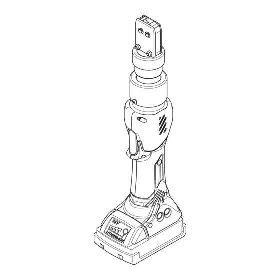
Page 12: Clamp Pincer Cp 10 / Cp 20 / Cc 20
Clamp pincer CP 10 / CP 20 / CC 20 3 Overview Clamp pincer CP 10 / CP 20 / CC 20 Fig. 2: Clamp pincer CP 10 / CP 20 / CC 20 Pincer jaws START button Pincer plate... -
Page 13: Accessories
• Test Equipment CAL 01, consisting of Calibrator CAL 01 and closing force sensor SKS 01, for measuring the pincer jaw force (closing force) and for calibrating clamp pincer CP 10 / CP 20 / CC 20 • AC adapter for operating the clamp pincer without a battery Issue 11.15... -
Page 14: Pc Software & Firmware
Plug & Play After the PC software supplied has been installed and clamp pincer CP 10 / CP 20 / CC 20 is connected to the PC via the USB cable, the computer automatically recognizes the pincer. When connected for the first time, this recognition of the clamp pincer may take a few minutes. -
Page 15: Manually Installing Pc Software
The PC software will start 2. Press START button on clamp pincer CP 10 / CP 20 / CC 20. 3. Connect clamp pincer CP 10 / CP 20 / CC 20 and PC with the USB cable. Updating firmware This function allows new firmware to be loaded to the device. - Page 16 Clamp pincer CP 10 / CP 20 / CC 20 4 PC software & firmware 1. Connect clamp pincer CP 10 / CP 20 / CC 20 and PC with the USB connection. 2. Remove battery (Fig. 5/1) from clamp pincer.
- Page 17 Clamp pincer CP 10 / CP 20 / CC 20 4 PC software & firmware 5. Select the new firmware version in the “Open” window and press the “Open” button to confirm the selection. Fig. 8: Confirming firmware selection The selected firmware will now be loaded. After the firmware has been loaded successfully the device powers on automatically, the loaded firmware is active and the firmware update is now complete.
-
Page 18: Use Of Clamp Pincer
Clamp pincer CP 10 / CP 20 / CC 20 5 Use of clamp pincer Use of clamp pincer Setting up clamp pincer 5.1.1 Manually entering and managing closing data parameters CAUTION Possible damage to clamp pincer! Entering incorrect closing data can cause the clamp pincer to malfunction. -
Page 19: Loading Closing Data From A File
Clamp pincer CP 10 / CP 20 / CC 20 5 Use of clamp pincer 4. Enter the value of the closing force holding time in the "Closing force holding time [ms]" field. 5. Click on the “Send data to device” button. -
Page 20: Calibrating Clamp Pincer
To ensure uniform and reproducible process quality calibration must be executed at least once per shift or once per day. Calibration is also necessary if any pincer components are exchanged. OETIKER recommends checking the closing force after calibration as an additional verification measure. It is critical to ensure that clamps are not closed in calibration mode. - Page 21 Clamp pincer CP 10 / CP 20 / CC 20 5 Use of clamp pincer 2. In the pop-up menu, click on OK to confirm. Initial calibration The “Calibration/Initial-calibration” window now opens. The initial closing force has already been input and doesn’t need to be re-entered.
- Page 22 Clamp pincer CP 10 / CP 20 / CC 20 5 Use of clamp pincer Closing force calibration INFO Reset the measuring instrument before starting the closing force calibration. If the CAL01 is being used, select the "Average” setting.
-
Page 23: Working With Clamp Pincer Cp 10 / Cp 20 / Cc 20
4. Click on the “OK” button. The pincer test is completed and the PC software changes to the "Status" tab start screen see chapter 7.2, p. 7-38. Working with clamp pincer CP 10 / CP 20 / CC 20 5.2.1 Battery charge level display The battery charge level is displayed on the battery charger LED (see also chapter 8.3, p. -
Page 24: Charging Battery
• The battery can stay in clamp pincer CP 10 / CP 20 / CC 20 to test the level of charge. In order to avoid uncertainty about the accuracy of the reading, however, clamp pincer CP 10 / CP 20 / CC 20 must be switched off for at least 1 minute prior to the test. -
Page 25: Aligning The Pincer Head
WARNING Risk of injury Body parts could get crushed if clamp pincer CP 10 / CP 20 / CC 20 is misused. Never insert your finger or other part of the body into the clamping area of the pincer head. -
Page 26: Performing Closure
INFO If there is no actuation of clamp pincer CP 10 / CP 20 / CC 20 for a certain period of time, it switches to sleep mode. Press the START button again. - Page 27 Clamp pincer CP 10 / CP 20 / CC 20 5 Use of clamp pincer The following description serves as an example for ear clamps. You can find more detailed information on OETIKER products from your local OETIKER representative. Prerequisites: –...
-
Page 28: Decommissioning Clamp Pincer Cp 10 / Cp 20 / Cc 20
(Fig. 18/2) out of clamp pincer CP 10 / CP 20 / CC 20 (Fig. 18/1). If necessary, clean any debris from the clamp pincer CP 10 / CP 20 / CC 20 after use and store in the case. Fig. 18: Removing battery Issue 11.15... -
Page 29: Output Of Closing Data Parameters
Output of closing data parameters INFO Prerequisites: – Clamp pincer CP 10 / CP 20 / CC 20 must be connected to the PC via the USB cable. – The status tab must be active (see Fig. 30, S. 7-37). 5.3.1 Creating single closure report 1. -
Page 30: Creating Multiple Closure Report
Clamp pincer CP 10 / CP 20 / CC 20 5 Use of clamp pincer 5.3.2 Creating multiple closure report 1. Click on the “Multiple report” button in the Status menu. 2. Select the desired date in the calendar. 3. Select the desired counters in the “Counter” list. -
Page 31: Maintenance And Repair
General safety instructions on maintenance and repair work • Clamp pincer CP 10 / CP 20 / CC 20 is designed for continuous use at a closure frequency of two closures per minute. After 40,000 closures, scheduled service must be performed. Otherwise the warranty lapses. -
Page 32: Maintenance
WARNING Risk of crushing by the clamp pincer Clamp pincer CP 10 / CP 20 / CC 20 is only completely disconnected from power when the battery is removed. Before performing maintenance work, remove the battery of clamp pincer CP 10 / CP 20 / CC 20. -
Page 33: Preventative Maintenance Work
WARNING Risk of crushing by the clamp pincer Clamp pincer CP 10 / CP 20 / CC 20 is only completely disconnected from power when the battery is removed. Before performing repair work, remove the battery of clamp pincer CP 10 / CP 20 / CC 20. - Page 34 6 Maintenance and repair NOTICE Damage to the clamp pincer by fitting unauthorized parts! Only use original OETIKER pincer jaws. Only fit the designated pincer jaw type in the pincer head. 1. Remove the battery. 2. Unscrew union nut (Fig. 24/2).
- Page 35 Clamp pincer CP 10 / CP 20 / CC 20 6 Maintenance and repair 6. Remove side plate (Fig. 27/9). Fig. 27: Removing the side plate 7. Remove compression spring (Fig. 28/11), cover plate(Fig. 28/12) and pincer jaws (Fig. 28/10).
-
Page 36: Pincer Head Replacement
Each type of clamp pincer can accept various different pincer heads. The type designations can be found in the tools catalog. • The pincer heads CP 10 / CP 20 / CC 20 can not be exchanged between models. Scope of delivery of a pincer head set •... -
Page 37: Description Of Pc Software
Clamp pincer CP 10 / CP 20 / CC 20 7 Description of PC software Description of PC software Structure of the PC software Each tab shows the “Device status” area and the status of data transmission and connection to the PC. -
Page 38: Status Menu
Clamp pincer CP 10 / CP 20 / CC 20 7 Description of PC software Status menu • Display of the closing force curve (progression of the closing force over time) of the most recent closure or any selected closure. - Page 39 Clamp pincer CP 10 / CP 20 / CC 20 7 Description of PC software Input field/Display field/Option Description field Loading closures from the device The calendar is used to select the process data for closures saved in the device.
-
Page 40: Closing Data Menu
Clamp pincer CP 10 / CP 20 / CC 20 7 Description of PC software Closing data menu This menu allows the target values for the closing force and holding time-closing force to be input. The image for the clamp pincer represents the device type actually connected. - Page 41 The closing force ranges for the clamp pincers are determined as follows: • CP 10 = closing force min. 800 N up to max. 4,500 N • CP 20 = closing force min. 3,500 N up to max. 10,000 N •...
-
Page 42: Calibration Menu
Fig. 33: Calibration menu Calibration of clamp pincer CP 10 / CP 20 / CC 20 is activated in the Calibration menu. If the device is modified (for instance by attaching a new pincer head – even if the article number is the same) or if a new target value for the closing force is input, the pincer must be checked. -
Page 43: Firmware Menu
Clamp pincer CP 10 / CP 20 / CC 20 7 Description of PC software The initial calibration closing force for the various devices is factory-set as follows: • CP 10 = Closing force 1000 N • CP 20 = Closing force 3500 N •... -
Page 44: Service Log Menu
Clamp pincer CP 10 / CP 20 / CC 20 7 Description of PC software Service log menu Above the “Write” button there is a window into which text can be input. Pressing the “Write” button then loads the text to the pincer. Communication between the user and service staff is facilitated because the communication content is inseparable from the pincer. -
Page 45: Additional Information Menu
Clamp pincer CP 10 / CP 20 / CC 20 7 Description of PC software Additional information menu The Additional information menu allows information to be called up from the headings that are listed. Fig. 36: Additional information menu Issue 11.15... -
Page 46: Attachment
General information in event of faults If the closure operation of clamp pincer CP 10 / CP 20 / CC 20 does not start or does not operate correctly, consult maintenance personnel responsible for clamp pincer CP 10 / CP 20 / CC 20. - Page 47 Clamp pincer CP 10 / CP 20 / CC 20 8 Attachment Display after the pressing operation Cause / remedy lights up orange Temperature error. Warm up the tool or cool it down. Display after plugging in the battery...
-
Page 48: Decommissioning And Storage
Clean clamp pincer CP 10 / CP 20 / CC 20 before storing. • Store clamp pincer CP 10 / CP 20 / CC 20 in the case in a clean, dry place and so it is protected from dust. Recommissioning •... -
Page 49: Accuracy Within The Working Temperature Range
Clamp pincer CP 10 / CP 20 / CC 20 8 Attachment 8.7.2 Clamp pincer CP 10 / CP 20 / CC 20 External dimensions Max. 310 × 70 × 80 mm (without battery and pincer head) Weight (including 2 Ah battery and standard pincer head) •... -
Page 50: Battery
Clamp pincer CP 10 / CP 20 / CC 20 8 Attachment 8.7.7 Battery Only the following batteries may be used: Article number Capacity 14002340 2.0 Ah 14002346 4.0 Ah Tab. 8: Batteries 8.7.8 AC power adaptor (not included in standard scope of supply) -
Page 51: Labels And Warnings On Cp 10 / Cp 20 / Cc 20
Clamp pincer CP 10 / CP 20 / CC 20 8 Attachment 8.7.10 Labels and warnings on CP 10 / CP 20 / CC 20 Fig. 39: Labels and warnings on the CP 10 / CP 20 / CC 20 Risk of crushing Rating plate, battery charger... -
Page 52: Warranty Conditions
Clamp pincer CP 10 / CP 20 / CC 20 8 Attachment 8.8.3 Warranty conditions • The clamp pincer must have been commissioned as specified in the instruction manual. • The clamp pincer housing must not have been opened. •... -
Page 53: Index
Clamp pincer CP 10 / CP 20 / CC 20 8 Attachment 8.10 Index Service LED ..........8-46 Error messages and troubleshooting measures 8-46 Accessories ............3-13 Battery and battery charger......3-13 CD-ROM with PC software......3-13 Faults Transport case ..........3-13 Clearing............ - Page 54 Clamp pincer CP 10 / CP 20 / CC 20 8 Attachment Structure ..........3-12, 7-37 Status LEDs ............3-12 PC software menu guide ........4-14 Status menu ............7-38 PC-software Storage and transport.......... 2-9 Creating single closure report ....... 5-29 Symbols and means of depiction ......
Need help?
Do you have a question about the CP 10 and is the answer not in the manual?
Questions and answers