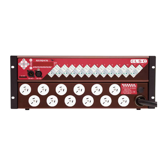
Summary of Contents for LSC Redback 12 Channel
- Page 1 12 Channel INSTALLATION and OPERATION Version 1.1 March 2009 L.S.C. Lighting Systems (Aust) Pty Ltd A.B.N. 21 090 801 675 Building 3, 66-74 Micro Circuit, South Dandenong Victoria 3175 Australia...
- Page 2 Accidental blank page Redback Dimmer Operator Manual V1.1 This page accidentally left blank. LSC Lighting Systems (Aust) Pty. Ltd...
-
Page 3: Table Of Contents
5.4.2 CHASE Menu LED ...........11 Advanced Menu ...........12 6.1 Accessing the Advanced Menus [ADV] ....12 6.2 Soft Patch ...............12 6.3 Fade Curve Selection ..........12 6.3.1 S Law Curve.............12 6.3.2 Square Law ............12 LSC Lighting Systems (Aust) Pty. Ltd Page i... -
Page 5: Redback Dimmer
Redback Dimmer Accidental blank page Operator Manual V1.1 This page accidentally left blank. LSC Lighting Systems (Aust) Pty. Ltd Page 1... -
Page 6: Meet The Redback
Note: The slot is not compatible with the SDHC (Secure Digital High Capacity) data format used in SD cards over 2GB. LSC Lighting Systems (Aust) Pty. Ltd Page 2... -
Page 7: Load Circuit Breakers
1.7 DMX512 sockets Redback is DMX512 (1990) or DMX512-A (E1-11) and RDM (E1-20) compliant, with standard XLR 5 pin Input and Through sockets. LSC Lighting Systems (Aust) Pty. Ltd Page 3... -
Page 8: Installation
Redback. Refer all that the neutral cable should be rated to carry servicing suitably qualified personnel. currents up to 75 Amps. LSC Lighting Systems (Aust) Pty. Ltd Page 4... -
Page 9: Fast Track Guide
The Redback can do just about anything that you will ever want from a compact digital dimmer, but you'll never know how to get the most from it if you don't read the manual. LSC Lighting Systems (Aust) Pty. Ltd Page 5... -
Page 10: Menu System
Redback is powered down or re- The two additional LEDs on either side of the set. level for dimmer 12 indicate that dimmer 12 is the dimmer currently selected for adjustment. LSC Lighting Systems (Aust) Pty. Ltd Page 6... -
Page 11: Data Entry
LOCKED then returns to the locked default screen. It is recommended that lock codes be easy to remember (eg. 1337 or 1991) but not obvious (eg.0000 or 9999). Whatever you choose, to LSC Lighting Systems (Aust) Pty. Ltd Page 7... -
Page 12: Menu Structure
Maximum Levels - dimmer maximum level settings TEST Dimmer testing ABOUT Software revision information SETUP Channel Setup - selection of 6 or 12 channel mode RESET Reboot system or Reset to System Defaults LSC Lighting Systems (Aust) Pty. Ltd Page 8... -
Page 13: Basic Menu
Levels set in this scene are combined on a highest-takes-precedence basis with levels from advanced scene memories, DMX512 control, the internal chaser and the optional MIDI interface. LSC Lighting Systems (Aust) Pty. Ltd Page 9... -
Page 14: Scene Menu Led
Applications include displays, signage and parties. In this screen: Left and Right arrow keys step between: • enabling and disabling chase effects. LSC Lighting Systems (Aust) Pty. Ltd Page 10... -
Page 15: Chase Menu Led
If the chase is active, the CHASE menu LED gives a short double-flash when Redback is displaying the default status screen. c5 - duplicated single channel Step Channels c6 - mexican wave Step Channels LSC Lighting Systems (Aust) Pty. Ltd Page 11... -
Page 16: Advanced Menu
2%. the dimmer as the channel is faded up and down. The Right arrow key activates the Curve menu and displays the currently selected dimmer and its assigned fade curve. LSC Lighting Systems (Aust) Pty. Ltd Page 12... -
Page 17: Redback's Advanced Scenes
(Range 0- • selecting each dimmer for setting 335,544 seconds). C 1 L 4 2 T 4 . 2 s The default fade time for all scenes 1.0 seconds. LSC Lighting Systems (Aust) Pty. Ltd Page 13... -
Page 18: Running A Scene
The Release number may be used to determine 6.10 Setting Maximum Dimmer if a new firmware update is available from the Levels Downloads area of the LSC web site at M A X L V www.lsclighting.com. The Maximum Level menu sets the highest possible level of dimmer output when its control signal is set to maximum. -
Page 19: Setup
The Reset menu provides two levels of reset. 240 Volts being fed to 120 Volt lamps. 6.14.1 System Reset (SYSRST) Shuts down and restarts (reboots) the Redback. All levels and memories are retained and LSC Lighting Systems (Aust) Pty. Ltd Page 15... -
Page 20: Dmx 512 Explained
DMX512 feeds. and causing possible errors. The Redback uses a high impedance DMX input circuit allowing you to loop the DMX signal from LSC Lighting Systems (Aust) Pty. Ltd Page 16... -
Page 21: Specifications
DMX512 (1990) or DMX512-A (E1-11) with RDM (E1-20) Channel output mimic LEDs DMX Data LEDs Operational STATUS indicator LED Number of cooling fans Fan cooling control Variable External software upgradeable 50/60Hz frequency Auto-select LSC Lighting Systems (Aust) Pty. Ltd Page 17... -
Page 22: Software (Firmware) Upgrades
In any event, LSC Lighting Systems (Aust) Pty. Ltd. can not be held liable for any direct, indirect, special, incidental, or consequential damages or loss whatsoever (including, without limitation, damages for loss...


Need help?
Do you have a question about the Redback 12 Channel and is the answer not in the manual?
Questions and answers