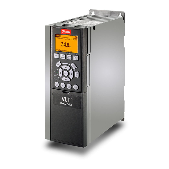
Danfoss VLT PROFIBUS DP MCA 101 Installation Manual
Frequency converter
Hide thumbs
Also See for VLT PROFIBUS DP MCA 101:
- Installation manual (6 pages) ,
- Programming manual (64 pages) ,
- Programming manual (60 pages)
Table of Contents
Advertisement
Quick Links
Download this manual
See also:
Programming Manual
Advertisement
Table of Contents

Summary of Contents for Danfoss VLT PROFIBUS DP MCA 101
-
Page 1: Installation Guide
MAKING MODERN LIVING POSSIBLE Installation Guide ® PROFIBUS DP MCA 101 ® Frequency Converter FC 102 • FC 103 • FC 202 FC 301/302 • FCP 106 • FCM 106 vlt-drives.danfoss.com... -
Page 3: Table Of Contents
3.9 Applying Power 3.10 Checking Network Cabling 4 Troubleshooting 4.1 Warnings and Alarms 4.2 Troubleshooting 4.2.1 LED Status 4.2.2 No Communication with the Frequency Converter 4.2.3 Warning 34 Fieldbus Fault Appears Index MG33C602 Danfoss A/S © 07/2015 All rights reserved. -
Page 4: Introduction
Danfoss partner. ® frequency converter and any master complying with the PROFIBUS standard. Communication can be configured via MCT 10 Set-up Software. The PROFIBUS interface supports PROFIBUS DP-V1. Danfoss A/S © 07/2015 All rights reserved. MG33C602... -
Page 5: Disposal
Numbered lists indicate procedures. Bullet lists indicate other information and description of illustrations. Italicised text indicates: • Cross-reference. • Link. • Footnote. • Parameter name. • Parameter group name. • Parameter option. MG33C602 Danfoss A/S © 07/2015 All rights reserved. -
Page 6: Safety
LEAKAGE CURRENT HAZARD Leakage currents exceed 3.5 mA. Failure to ground frequency converter properly can result in death or serious injury. • Ensure the correct grounding of the equipment by a certified electrical installer. Danfoss A/S © 07/2015 All rights reserved. MG33C602... - Page 7 An internal failure in the frequency converter can result in serious injury, when the frequency converter is not properly closed. • Ensure that all safety covers are in place and securely fastened before applying power. MG33C602 Danfoss A/S © 07/2015 All rights reserved.
-
Page 8: Installation
If an MCB option is installed, only top cable entry an angle of 90°. is possible. Remove the knock-out plate from the new LCP cradle. Mount the new LCP cradle. Danfoss A/S © 07/2015 All rights reserved. MG33C602... - Page 9 Illustration 3.3 Top Cable Entry: Option Mounted with Connector Facing Up LCP cradle ® PROFIBUS DP MCA 101 option card Connector plug Illustration 3.2 Exploded View Illustration 3.4 Bottom Cable Entry: Option Mounted with Connector Facing Down MG33C602 Danfoss A/S © 07/2015 All rights reserved.
-
Page 10: Mounting In A Vlt ® Drivemotor Fcp 106 Frequency Converter
Address. For setting the address from parameter 9-18 Node Address, ensure that all address switches are set to ON. When the address is already set using address hardware switches, the address value shown in parameter 9-18 Node Address is read-only. Danfoss A/S © 07/2015 All rights reserved. MG33C602... -
Page 11: Electrical Installation
When the fieldbus is extended with a repeater, terminate the extension at both ends. NOTICE To avoid impedance mismatch, use the same cable type throughout the entire network. Refer to chapter 3.7.2 Cable Specifications for cable specifications. MG33C602 Danfoss A/S © 07/2015 All rights reserved. - Page 12 3.7.2 Cable 9.6–187.5 1000 2000 3000 4000 Specifications. kBaud 500 kBaud 1200 1600 1.5 MBaud 3–12 MBaud Table 3.4 Maximum Total Bus Cable Length, including Drop Cables Danfoss A/S © 07/2015 All rights reserved. MG33C602...
- Page 13 Illustration 3.10 Fieldbus Cable Terminal Connections 1 Cable screen 2 EMC bracket (used for top cable entry only) Illustration 3.9 Wiring for Enclosure Sizes A1–A3 MG33C602 Danfoss A/S © 07/2015 All rights reserved.
- Page 14 Illustration 3.12. Tighten cable glands securely. Illustration 3.11 Wiring for Enclosure Sizes A4–A5, B1–B4, and C1–C4 Illustration 3.12 Wiring for Enclosure Sizes D, E, and F Danfoss A/S © 07/2015 All rights reserved. MG33C602...
-
Page 15: Reassembling Cover
PROFIBUS master. Check that the bit baud rate search in parameter 9-53 Profibus Warning Word is not active. Illustration 3.13 PROFIBUS Wiring for FCP 106, MH1–MH3 MG33C602 Danfoss A/S © 07/2015 All rights reserved. -
Page 16: Troubleshooting
Wrong configuration data from PLC. 00000800 Wrong ID sent by PLC. 00001000 Internal error occurred. 00002000 Not configured. 00004000 Timeout active. 00008000 Warning 34 active. Table 4.1 Parameter 9-53 Profibus Warning Word Danfoss A/S © 07/2015 All rights reserved. MG33C602... -
Page 17: No Communication With The Frequency Converter
If not, terminate the bus connection with termination resistors at the initial and final nodes. Action: • Check the master mode and master configu- ration. • Check the wiring for correct master mode and communication. MG33C602 Danfoss A/S © 07/2015 All rights reserved. -
Page 18: Index
Exploded view..................7 Wiring procedure.................. 11 Grounding....................6 High voltage..................... 4 Installation, electrical................9 Intended use..................... 2 Items supplied..................2 Leakage current..................4 LED panel....................14 LED status....................14 Load sharing..................... 4 Danfoss A/S © 07/2015 All rights reserved. MG33C602... - Page 19 Index Installation Guide MG33C602 Danfoss A/S © 07/2015 All rights reserved.
- Page 20 Danfoss can accept no responsibility for possible errors in catalogues, brochures and other printed material. Danfoss reserves the right to alter its products without notice. This also applies to products already on order provided that such alterations can be made without subsequential changes being necessary in specifications already agreed. All trademarks in this material are property of the respective companies.


