
Related Manuals for DAEWOO ELECTRONICS FR-540N


Summary of Contents for DAEWOO ELECTRONICS FR-540N
- Page 1 S/M No. : FR540NT010 Service Manual Refrigerator Model:FR-540N DAEWOO ELECTRONICS CO., LTD.
- Page 2 1. SPECIFICATION MODEL NAME FR-540N 200g Refirgerant R134a 170g Cooling System Fan Cooling Convection Refrigeration System Air Forced Convection Defrost System Fin Evaporator Forced Automatic Start & Stop Defrost Operation Cold Control Adjustable Button Freezer Refrigerator Capacity Total Height 1768mm...
-
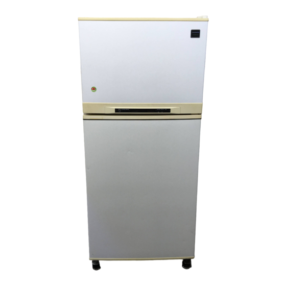
Page 3: External View
2. EXTERNAL VIEW... -
Page 4: Wire Diagram
3. WIRE DIAGRAM R-F/M F-SENSOR OR X 2 BL X 2 COMMON D-SENSOR D-HTR COMP R1-SENSOR DR S/W F-F/M 1 3 4 R ROOM LAMP DR S/W P-RELAY M-PCB PLUG L/BL BL X 2 HARNESS 14PIN F-F/M GN/YW TEMP FUSE R-F/M F-PCB COMPRESSOR... -
Page 5: Name Of Parts
4. NAME OF PARTS 1. FR-540N 1 Freezer Lamp 2 Freezer Shelf 3 Case Icing 4 Guide Icing 5 Ice Box 6 Chilled Door 7 Chilled Case 8 Deodorant 9 Refrigerator Side Louver 10 Refrigerator Shelf 11 Cover Cubic Duct... -
Page 6: Air Flow Diagram
5. AIR FLOW DIAGRAM 1. FR-540N Freezer door pocket Do not put ice cream or frozen Freezer room food in freezer door pocket to Do not put any bottle such as store for a long term. Opening beer or beverage because it can... -
Page 7: Refrigerant Cycle Diagram
6. REFRIGERANT CYCLE DIAGRAM ACCUM SUC-PIPE COOLING PIPE... -
Page 8: Machine Room View And Part List
7. MACHINE ROOM VIEW AND PART LIST PART NAME PART NAME PART NAME BASE COMPRESSOR DRYER BIND WIRE COMPRESSOR PIPE CON (SUC) PLUG POWER AS ABSORBER COMPRESSOR VIBRATIONPROOF GUM SCREW MACHINE WASHER COMP. *T PIPE CON (AUX) PIPE CON (HOT) SWITCH P-RELAY AS HOSE DRAIN (B) TAPE OPP... -
Page 9: Main Components
8. MAIN COMPONENTS 1. COMPRESSOR Refrigerant Voltage 100V/50,60Hz 110V/60Hz 115, 120V/60Hz 127V/60Hz 220V/50Hz 220V/60Hz 230V/50Hz 240V/50Hz Comp. model BL25YE-3 BL25YE-1 PL28YE-6 PL25YE-4 PL28YE-6 Part code 3952125C30 3952125C10 3956128C60 3956128C40 3956128C60 Strating type RSCR RSCR RSCR Refrigerant R134a Voltage 100V/50,60Hz 110V/60Hz 115, 120V/60Hz 127V/60Hz 220V/50Hz... - Page 10 220V/60Hz 230V/50Hz 240V/50Hz Spec. 3211DWBFM 3211DWBFU 3211DWBFQ 3211DWBFE 3211DWBFS Part code 3011800850 3011801000 3010027220 3015902600 3011801030 7. DEFROST HEATER 1) FR-540N Refrigerant R12, R134a Voltage 100V/50,60Hz 110V/60Hz 115, 120V/60Hz 127V/60Hz 220V/50Hz 220V/60Hz 230V/50Hz 240V/50Hz Spec. 148W 148W Part code 3012801300...
- Page 11 8. LAMP ASSEMBLY Refrigerant R12, R134a Voltage 100V/50,60Hz 110V/60Hz 115, 120V/60Hz 127V/60Hz 220V/50Hz 220V/60Hz 230V/50Hz 240V/50Hz Spec. Part code 3013600010 3013600000...
- Page 12 9. PCB TRANSFORMER 1) FR-540N Refrigerant R12, R134a Voltage 100V/50,60Hz 110V/60Hz 115, 120V/60Hz 127V/60Hz 220V/50Hz 220V/60Hz 230V/50Hz 240V/50Hz Part code 5EPK057700 5EPK057609 5EPK042000 5EPK057030 5EPK057630...
- Page 13 10. MAIN PCB ASSEMBLY 1) FR-540N Refrigerant R12, R134a Voltage 100V/50,60Hz 110V/60Hz 115, 120V/60Hz 127V/60Hz 220V/50Hz 220V/60Hz 230V/50Hz 240V/50Hz Spec. N803 N803 Part code 3014303620 3014302540...
- Page 14 11. DRYER Refrigerant R134a Spec. 10 g 15 g Part code 3016800103 3016801100...
- Page 15 POWER CORD SPECIFICATION SHAPE OF POWER CODE PART CODE DESCRIPTION REMARK 3011315000 CP-2PIN FOR EUROPEAN COUNTRY 401RA17200 CP-2PIN FOR OTHER COUNTRY 4006D17101 KP-30 FOR AMERICA 401PD17101 KP-211 FOR JAPAN & TAIWAN 3011300801 BP-3PIN 3011303010 #267 FOR CHILE 3011315310 FOR ISRAEL FOR U.K, MIDDLE ASIA 3011303050 BS-1363A...
-
Page 16: Door Color Specification
9. DOOR COLOR SPECIFICATION 1. FR-540N 1. ASSEMBLY URETHAN FREEZER DOOR Refrigerant R134a Key type Dull lamina High glossy High glossy Dull lamina High glossy High glossy Normal PCM Normal PCM sheet lamina sheet bright PCM sheet lamina sheet bright PCM... - Page 17 COLOR TABLE 1. PCM type COLOR CHIP COLOR NAME P/WITH (WH069) '94 L/GRAY (GY158) '95 L/GRAY (GY259) '94 M/GRAY (GY331) '95 M/GRAY (GY335) '97 M/GRAY (GY267) M. D/GRAY (GY750) N/BLUE (BL718) MINT GREEN (GN206) '97 BEIGE (BE215)
- Page 18 2. Lamina sheet type COLOR CHIP COLOR NAME P/WITH (WH069) '94 L/GRAY (GY158) '95 L/GRAY (GY259) '94 M/GRAY (GY331) '95 M/GRAY (GY335) '97 M/GRAY (GY267) M. D/GRAY (GY750) N/BLUE (BL718) MINT GREEN (GN206) S/GOLD G/GREEN...
- Page 19 10. EXPLODED VIEW AND PARTS LIST 1. FR-540N 1. Exploded view...
- Page 20 2. Parts list PART CODE PART NAME DESCRIPTION QUANTITY REMARK ASSY URT CAB 4018G57110 GUIDE DRN *O 3011408100 COVER HTR *U HEATER GLAS TUBE AS REFER TO # 10 3011408200 COVER HTR *T 4010G19010 FIXTURE DEFR HTR 3017000701 EVAPORATOR SAS 3014801201 SENSOR F D AS PTC-KD38-FD6 ABS TYPE...
- Page 21 PART CODE PART NAME DESCRIPTION QUANTITY REMARK 3011410000 COVER M/PCB BOX AS 3015501200 WINDOW R DRYER AS REFER TO # 11 3012901400 HINGE *T AS ASSY URT *T DOOR REFER TO # 13 3017402202 LINER F DR ABS 1.4 x 785 x 1140 3012300600 GASKET F DR AS PVC-S...
-
Page 22: Electronic Function
11. ELECTRONIC FUNCTION 1. FR-540N 1) How to use the panel • The temperature inside the freezer and refrigerator room is • The comp and fan in the refrigerating room controlled automatically according to the customer’s purpose operate for 40 min. - Page 23 2) Function table Control Control Contents Remark Function Objects Initial Time 1. In the initial operation, the temperature of FRZ. and REF. operation Temperature automatically set at 3/3. control 2. The clock is set at 12:00. QUICK FREEZER QUICK FRIDGE TIME FUZZY FREEZING...
- Page 24 Control Control Contents Remark Function Objects 4. Time chart of each device. COMP F-FAN C-FAN 30" 5. COMP. on/off temperature (Temperature ˚C/Resistance kΩ) COMP. OFF -21/23.6 -21/23.6 -22/25.0 -23/26.4 -24/27.9 -25/29.6 COMP.ON -16/17.9 -16/17.9 -17/18.9 -18/20.0 -19/21.1 -20/22.3 Refrigerator R-fan 1.
- Page 25 Control Control Contents Remark Function Objects Quick COMP. 1. If quick freezing button is pressed, the clock mode is changed freezing F-fan to quick freezing time mode. C-fan QUICK FREEZER QUICK FRIDGE TIME FUZZY FREEZING TEMP. FRIDGE. TEMP. FRZ. REF. FRESH 1 2 3 F 5 4...
- Page 26 Control Control Contents Remark Function Objects 3. The bar LED is illuminated 3 times in a row. REF. REF. F 5 4 3 2 1 E. F F 5 4 3 2 1 E. F Quick mode ON After 30 min. REF.
- Page 27 Control Control Contents Remark Function Objects Determination 1. Defrost function is started by the following 4 conditions. Condition 1 : Accumulated COMP. on time (MAX. and MIN. defrost time) Condition 2 : Accumulated door open time (different from the accumulated door open time in fuzzy function) Condition 3 : COMP.
- Page 28 Control Control Contents Remark Function Objects Deciding defrosting period Is it min. accumulated COMP ON time? Is the percentage of operation, so far, above 80%? Is it max. accumulated COMP ON time? Is the resuting accumulated door open time, 10 min? Is the percentage of operation, so far, above 80%? Will it be min.
- Page 29 Control Control Contents Remark Function Objects Device COMP. 1. Pressing the SW01 on M-PCB enables device test function. test F-fan 2. Pressing the SW01 proceeds the operation of device as function R-fan follows. Heater COMP. D-heater break F-fan R-fan return 3.
- Page 30 Control Control Contents Remark Function Objects COMP. 1. The low cooling prevention function will be operating if the cooling R-fan temperature of R1-sensor or R2-sensor goes above 6˚C. prevent 2. Time chart function low cooling detection temp. (6˚C) R-FAN ON : ON R-FAN OFF : OFF...
- Page 31 Control Control Contents Remark Function Objects 4. Sensor’s temperature indication is as follow. 1) R-sensor (when 1˚C) FRZ. REF. FRESH 1 2 3 5 4 3 2 1 E. F CLEAN 2) D-sensor (when -23˚C) FRZ. REF. FRESH 1 2 3 5 4 3 2 1 E.
- Page 32 3) Self-diagnosis table Code Content Perception method Refrigerator operation state F-sensor - Short circuit - The refrigerator is run at 60% power with a malfunction 40 minute period. - Wire disconnection - When the refrigerator compartment is over frosted, the operation is forcibly stopped, then returns to a 40 minute period operation.
- Page 33 4) Circuit and Wiring Diagram N 8 0 2 M-PCB CN06 F-PCB 26.7K F-SENSOR 1. The RESISTOR value which has not displayed time constant is 10K 1/4W. CE12 D-SENSOR CC11 2. The CERAMIC CONDENSOR which been displayed time constant is 0.01µF. R2.3 D03 D06 D05 D01 D02 SCAN A...
Need help?
Do you have a question about the FR-540N and is the answer not in the manual?
Questions and answers
Cómo puedo programar el frío del Frezzer de la heladera dewo fr 540
To set the freezer temperature on the Daewoo Electronics FR-540N refrigerator, press the freezer temperature button. The display will cycle through different stages in the following order:
1. R1-sensor temperature
2. D-sensor temperature
3. F-sensor temperature
4. Error code
If no button is pressed for 8 minutes, the display will return to normal automatically.
This answer is automatically generated
كيفية ا،جاع اعدادات المصنع
كيف اقوم بضبط مدة التجميد