
Subscribe to Our Youtube Channel
Related Manuals for UnionSpecial 54200J-12-16


Summary of Contents for UnionSpecial 54200J-12-16
- Page 1 ADJUSTING INSTRUCTIONS 54200 SERIES MANUAL NO. INS9203 STYLES 54200J-12-16 REV. 10/22/98...
- Page 2 Union Special Corporation Rights Reserved In All Countries PREFACE This technical manual has been prepared to guide you while adjusting the 54200J-12-16 machine. It may be used in conjunction with Union Special Parts Manual PRT9204 and Union Special Catalog 102L.
- Page 3 SAFETY RULES CAUTION! THESE SYMBOLS INDICATE THAT YOUR PERSONAL SAFETY IS INVOLVED This equipment is designed to operate under specified voltage requirements. The electrical power to the equipment MUST match the voltage specifications for the equipment. Before operating the machine check the direction of rotation of the handwheel. Breakage may occur if the direction of rotation is incorrect.
-
Page 4: Table Of Contents
CONTENTS MACHINE IDENTIFICATION ..........................5 CLASS DESCRIPTION ............................5 MACHINE STYLE ..............................5 NEEDLES ................................5 THREADING ................................6 OILING ..................................7 TORQUE REQUIREMENTS ........................... 7 NEEDLE HEAD ALIGNMENT ..........................8 SETTING THE NEEDLE BAR HEIGHT ........................8 SETTING THE LOOPER HOLDER REST ......................8 SETTING THE LOOPER HOLDER THRUST AND THROW-OUT SPRING TENSION .......... -
Page 5: Machine Identification
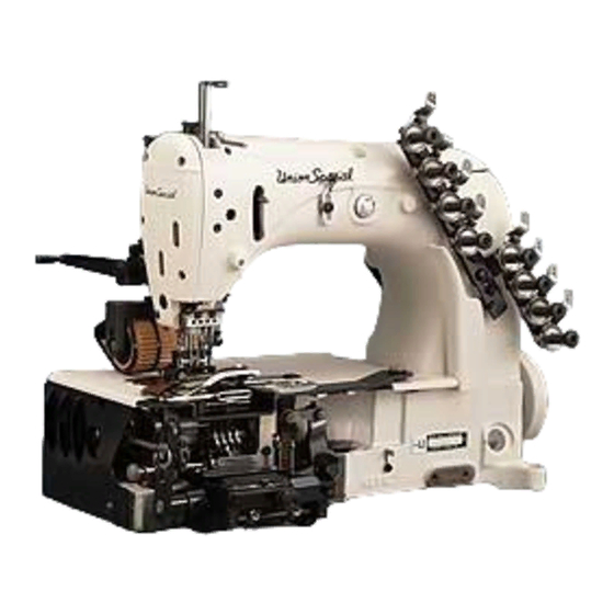
Filter type oil return pump, oil pan base plate and head oil siphon assembly. MACHINE STYLE 54200J-12-16 For decorative stitching operations on men 9 s, women 9 s and children’s jackets, coats, beachwear and similar operations on medium to heavy- weight material. -
Page 6: Threading
THREADING The above illustration shows the proper way to thread the 54200J-12-16. Each thread on the tension assembly has a number or letter that must correspond with the same number or letter on the needle head and looper eyelets. Note that the needles are inserted at a right angle to the needle head with the s carf... -
Page 7: Oiling
OILING Referring to Figure 1, fill the machine at (A) until the oil level is indicated between the red lines on gauge (B). Use a straight mineral oil, Saybolt viscosity of 90 to 125 seconds at 1000 fahrenheit. Run the machine slowly for a few minutes to allow the wicks to carry oil to the bearings. -
Page 8: Needle Head Alignment
NEEDLE HEAD ALIGNMENT Insert a new set of needles, type and size as specif ied in the description of the machine. Needles must be inserted with the spot or scarf to the left. Turn the handwheel in oper- ating direction to bring needles (A,Fig. 2) down to ensure that they are aligned in the needle slots of the throat plate as shown. -
Page 9: Setting The Looper Holder Thrust And Throw-Out Spring Tension
SETTING THE LOOPER HOLDER THRUST AND THROW-OUT SPRING TENSION The looper throw-out tension must be set so the looper holder will “snap” to the threading position when the looper holder throw-out pin is disengaged. Turn the handwheel in operating direction until the needles are at their highest position and pull looper throw-out knob (A, Fig. -
Page 10: Setting The Looper Gauge (Cont.)
SETTING THE LOOPER GAUGE (CONT.) Move the needle guard to the side so the needle will not strike it. Turn the handwheel in operating direction until the looper holder frame has travelled fully to the rear. At this time the distance between the centerline of the needles and the points of the loopers should be 1/8"... -
Page 11: Setting The Retainers (Cont.)
SETTING THE RETAINERS (CONT.) NOTE: To return the looper holder to a sewing position pull the looper throw-out plunger knob to the left and push against the looper holder frame. Release knob. To adjust the retainers from the right to left turn the handwheel in operating direction with the loopers travelling toward the... -
Page 12: Setting The Feed Dog (Cont.)
SETTING THE FEED DOG (CONT.) To center the feed dog from left to right rotate the handwheel in operating direction until the feed dog is at its highest position. Loosen screws (A and B, Fig. 12) and move feed rocker (C) right or left on feed rocker shaft (D) as Retighten screws (A and B). -
Page 13: Setting The Tension Release
SETTING THE TENSION RELEASE The tension release is set properly so it begins to function when the presser foot has been raised 1/8" (3.2mm) from the throat plate sur- face and the tension disc is entirely released when the presser foot reaches its highest position. -
Page 14: Timing The Puller (Cont.)
TIMING THE PULLER (CONT.) and loosen. Continue to rotate the handwheel c A until screw (A) is accessible and loosen. Hold the eccentric in this position and rotate the handwheel until the needles reach the top of their stroke. Push the eccentric against the thrust collar and tighten screw (A). -
Page 15: Setting The Thread Eyelets
SETTING THE THREAD EYELETS Set looper thread take-up eyelet (A, Fig. 19) so take-up pin (B) begins to function when the loopers start their travel to the rear. Set frame needle thread eyelet (A, Fig. 20) as high as possible without pulling thread through the tensions on the downward stroke of the needle bar.
Need help?
Do you have a question about the 54200J-12-16 and is the answer not in the manual?
Questions and answers