UnionSpecial 56100 Original Instructions Manual
Bag seaming machine
Hide thumbs
Also See for 56100:
- Original instructions manual (52 pages) ,
- Original instructions manual (8 pages) ,
- Adjusting instructions and illustrated parts list (32 pages)
Table of Contents
Advertisement
Quick Links
ORIGINAL INSTRUCTIONS AND ILLUSTRA
ORIGINAL INSTRUCTIONS AND ILLUSTRATED P
ORIGINAL INSTRUCTIONS AND ILLUSTRA
ORIGINAL INSTRUCTIONS AND ILLUSTRA
ORIGINAL INSTRUCTIONS AND ILLUSTRA
ORIGINALBETRIEBSANLEITUNG UND ILLUSTRIERTES
ORIGINALBETRIEBSANLEITUNG UND ILLUSTRIERTES
ORIGINALBETRIEBSANLEITUNG UND ILLUSTRIERTES
ORIGINALBETRIEBSANLEITUNG UND ILLUSTRIERTES
ORIGINALBETRIEBSANLEITUNG UND ILLUSTRIERTES
CLASS 56100
CLASS
CLASS
CLASS
CLASS
KLASSE 56100 -SACKNÄHMASCHINE
KLASSE 56100 -SACKNÄHMASCHINE
KLASSE 56100 -SACKNÄHMASCHINE
KLASSE 56100 -SACKNÄHMASCHINE
KLASSE 56100 -SACKNÄHMASCHINE
MANUAL NO. / KATALOG NR. PT1401SABT2A-GR EN-DE
10_16
TEILEVERZEICHNIS
TEILEVERZEICHNIS
TEILEVERZEICHNIS
TEILEVERZEICHNIS
TEILEVERZEICHNIS
56100
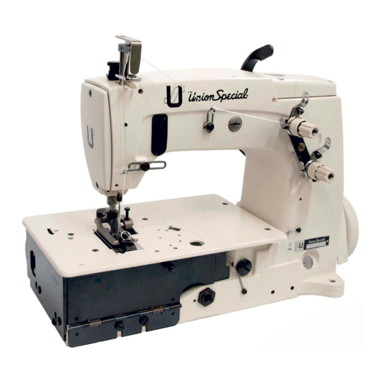
56100 BAG SEAMING MACHINE
56100
BAG SEAMING MACHINE
BAG SEAMING MACHINE
BAG SEAMING MACHINE
56100
BAG SEAMING MACHINE
FOR STYLE / FÜR TYP
56100SABT2A
TED P
TED PAR
TED P
ARTS MANUAL
AR
AR
TS MANUAL
TS MANUAL
TS MANUAL
TED P
AR
TS MANUAL
Advertisement
Table of Contents

Related Manuals for UnionSpecial 56100


Summary of Contents for UnionSpecial 56100
- Page 1 ORIGINALBETRIEBSANLEITUNG UND ILLUSTRIERTES TEILEVERZEICHNIS TEILEVERZEICHNIS TEILEVERZEICHNIS TEILEVERZEICHNIS TEILEVERZEICHNIS CLASS CLASS 56100 CLASS 56100 56100 56100 BAG SEAMING MACHINE BAG SEAMING MACHINE BAG SEAMING MACHINE BAG SEAMING MACHINE CLASS CLASS 56100 BAG SEAMING MACHINE KLASSE 56100 -SACKNÄHMASCHINE KLASSE 56100 -SACKNÄHMASCHINE KLASSE 56100 -SACKNÄHMASCHINE KLASSE 56100 -SACKNÄHMASCHINE...
- Page 2 SAFETY RULES SAFETY RULES SAFETY RULES SAFETY RULES SAFETY RULES SICHERHEITSHINWEISE SICHERHEITSHINWEISE SICHERHEITSHINWEISE SICHERHEITSHINWEISE SICHERHEITSHINWEISE Before putting the machines described in this manual Lesen Sie vor Inbetriebnahme der in diesem Katalog into service, carefully read the instructions. The starting beschriebenen Maschinen die Betriebsanleitung of each machine is only permitted after taking notice sorgfältig.
-
Page 3: Machine Description
Wartungs-, Reparatur- und Umbauarbeiten (siehe Maintenance, repair and conversion work (see Punkt 8) dürfen nur von Fachkräften oder ent- item 8) must be done only by trained technicians sprechend unterwiesenen Personen unter Beach- or special skilled personnel under condsideration tung der Betriebsanleitung durchgeführt werden. of the instructions. - Page 4 Definition of application as foreseen respectivelly Definition of application as foreseen respectivelly Definition of application as foreseen respectivelly Definition of application as foreseen respectivelly Definition of application as foreseen respectivelly Erläuterung des bestimmungsgemäßen Gebrauchs Erläuterung des bestimmungsgemäßen Gebrauchs Erläuterung des bestimmungsgemäßen Gebrauchs Erläuterung des bestimmungsgemäßen Gebrauchs Erläuterung des bestimmungsgemäßen Gebrauchs use as foreseen:...
-
Page 5: Threading And Oiling Diagram
Fig. 1 EINFÄDELN UND ÖLEN THREADING AND OILING DIAGRAM Für das Nahtbild 401 fädeln Sie die Maschine, wie oben For 401 stitch, thread machine as indicated above. abgebildet, ein. Das Einfädeln des Greifers ist der Über- The looper threading has been enlarged for clarity. sichtlichkeit wegen vergrößert abgebildet. -
Page 6: Oil Specification Requirements
OIL SPECIFICATION REQUIREMENTS ERFORDERLICHE ÖL-SPEZIFIKATIONEN All oils shall be non compounded, straight mineral oils, Sämtliche Öle sollten ungebundene, pure Mineralöle mit of high viscosity index (will not thin down excessively hoher Viskosität sein (verdünnen sich bei Hitze nicht über- with heat). Practically all oil companies have Union mäßig). -
Page 7: Besonders Zu Beachten
LUBRICATION ÖLEN Before operating fill the machine with oil at plug screw Bevor Sie die Maschine in Betrieb nehmen, füllen Sie (A, Fig. 2). While filling machine with oil, check gauge (B). diese bei der Verschlussschraube (A, Fig. 2) mit Öl. Wäh- When proper oil level is reached, the oil level should rend Sie die Maschine mit Öl füllen, kontrollieren Sie den appear in the center between both read lines. -
Page 8: Synchronizing Looper And Needle Motion
SYNCHRONIZING LOOPER AND NEEDLE MOTION SYNCHRONISIERUNG DER GREIFER- UND NADELBEWEGUNG Synchronization is the most important adjustment Die Synchronisierung ist die wichtigste Einstellung bezüglich involving the needle and looper motion relation, der Nadel- und Greiferbewegungsrelation, da diese die because it maintains the needle-looper relation at Nadel-Greiferrelation bei der Fadenschlingenbildungszeit both the needle loop taking time, as well as when the sowie die Zeit des Nadeleintritts in das Greiferdreieck kon-... - Page 9 SYNCHRONISIERUNG DER GREIFER- UND NADEL- SYNCHRONIZING LOOPER AND NEEDLE MOTION BEWEGUNG (FORTSETZUNG= CONTINUED) Fig. 3B If synchronization gauge set TT34 is not available, the Falls die Synchronisierungslehr eTT34 nicht verfügbar ist, following procedure can be used. kann die nachfolgende Vorgehensweise angewendet werden.
- Page 10 Fig. 5 Lösen Sie die Sicherungsmutter (F) und ziehen Sie die Loosen lock nut (F) and TORQUE thrust adjusting screw Spannungseinstellschraube (E) mit einem Drehmoment (E) to 6 in. lbs (7cm/kg), re-tighten lock nut (F) securely. von 7cm/kg (0.686 Nm) an . Ziehen Sie die Sicherung wieder fest an.
-
Page 11: Looper Setting
GREIFEREINSTELLLUNG LOOPER SETTING Kontrollieren Sie den Abstand zwischen Mitte Nadel- Check the distance between middle of bearing as- lager 29476LV am Greiferantriebshebel 56342K (A Fig.. sembly 29476LV at looper lever 56243K (A Fig. 6) 6) und der Mitte des Greiferhebels 29192V (B Fig. 6). and middle of rocker assembly 29192V (B Fig. -
Page 12: Needle Bar Height
NEEDLE BAR HEIGHT NADELSTANGENHÖHE Die Höhe der Nadelstange (A, Fig.8) ist richtig, wenn Height of needle bar (A, Fig. 8) is correct when the top die Oberkante des Nadelöhrs mit der Unterkante des of the needle eye is even with the lower edge of the Greifers eine Linie bildet und die Spitze des Greifers looper and the point of the looper is behind the needle hinter der Nadel und 0,2 - 0,5 mm links von der Nadel... - Page 13 CLOSE SETTING OF THE LOOPER TO THE NEEDLES DICHTSTELLEN DER GREIFER ZU DEN NADELN When the handwheel is turned in sewing direction and Wenn das Handrad in Nährichtung gedreht wird und the loopers (A, Fig. 9) move to the left, their tips have to die Greifer (A, Fig.
-
Page 14: Feed Dog Setting
FEED DOG SETTING TRANSPORTEUREINSTELLUNG Feed dog (A, Fig. 10) should be centered in throat plate Der Transporteur (A, Fig. 10) sollte mittig von allen Seiten (B) with equal clearance on all sides and ends with feed in der Stichplatte (B) sein, wenn der Stoffvorschub auf travel set to desired stitch length. -
Page 15: Changing Stitch Length
CHANGING STITCH LENGTH STICHLÄNGENEINSTELLUNG Set the stitch to required length. This is accomplished by Stellen Sie die Stichlänge nach Bedarf ein. Dies erfolgt loosening lock nut (A, Fig. 12) 1/2 turn, (it has a left hand durch Lösen der Mutter (A, Fig. 12) 1/2 Drehung (Links- thread) on the end of the stitch regulating stud and gewinde) am Ende der Stichregulierungsschraube und turning stitch adjusting screw (B) located under the left... -
Page 16: Einstellung Des Obertransporteurs
EINSTELLUNG DES OBERTRANSPORTEURS SETTING OF THE UPPER FEED DOG Der Obertransporteur wird mit der Schraube (A, Fig. The upper feed dog is screwed on with screw (A, Fig. 14) in der Führung, wie im Bild gezeigt, angeschraubt. 14) to the guide as shown in picture. Die Schraube (B) mit der Kontermutter (C) dient der Screw (B) with the lock nut (C) is used for height Höheneinstellung des Obertransporteurs. - Page 17 EINSTELLUNG DER DRÜCKERFUSSSTANGE PRESSER BAR SETTING Die Drückerfußstangenverbindung und -führung Presser bar connection and guide 51257M have to 51257M muss, wenn der Drückerfuß auf der Stichplatte be adjusted in such a way that when the presser foot aufliegt so eingestellt sein, dass zwischen der Unter- rests on the throat plate there should be a distance of kante der Drücker fußstangenverbindung und - ±...
- Page 18 EINFÄDELN THREADING Ziehen Sie die Greifer- und Nadelfäden in die Maschine Draw looper and needle threads into the machine and start operating on a piece of fabric. Refer to threading und nähen Sie auf einem Stück Stoff. Beziehen Sie sich auf das Diagram (Fig.
-
Page 19: Erforderliche Drehmomente
TORQUE REQUIREMENTS ERFORDERLICHE DREHMOMENTE Torque specification given in the catalog are measured Drehmomentangaben in diesem Katalog sind in inch- in inch-pounds or centimeter/kilograms. All straps and pounds oder in Zentimeter/Kilogramm vorgegeben. eccentrics must be tightened to 19-21 in. lbs. (22-24cm/ Alle Bügel und Exzenter müssen mit 22-24cm/kg kg) unless otherwise noted. -
Page 20: Aligning Mainshaft To Crankshaft
ALIGNING MAINSHAFT TO CRANKSHAFT AUSRICHTEN DER HAUPTWELLE ZUR KURBELWELLE As viewed looking down from rear of machine, spot Wenn man vom hinteren Teile der Maschine hinabsieht, screws (A, Fig. 19) in the couplings must align with the müssen die Schrauben (A, Fig. 19) in den Ver- spots in the looper drive crank (B) and set screws (C) schraubungen mit den Spitzlöchern in der Greifer- must align with the flats on crankshaft (D) and mainshaft... - Page 21 Fig. 21 The oil drip plate (A, Fig. 21) located in the oil reservoir Das Öltropfblech (A, Fig. 21), das sich im Ölbehälter should be positioned with its tip in the recessed cut out befindet, sollte mit seiner Spitze in der vertieften in the bed casting, as far to the left as possible without Aussparung des Gehäuses positioniert werden, so weit touching.
- Page 22 ROUBLE SHOOTING: When sewing problems occur (malformed stitches) always change needle first! FEHLERSUCHE: Bei auftretenden Nähproblemen (Fehlstiche) immer zuerst die Nadel wechseln! Ö f l e t s i o f r i e r r e f . t l c ü...
-
Page 23: Identifying Parts
ORDERING REPAIR PARTS BESTELLEN VON ERSATZTEILEN ILLUSTRATIONS ABBILDUNGEN This catalog has been arranged to simplify ordering Dieser Katalog wurde zusammengestellt, um die Er- repair parts. Exploded views of various sections of the satzteilbestellung zu erleichtern. mechanism are shown so that the parts may be seen Jede Explosionszeichnung stellt einen Teil der Maschine in their actual position in the machine. - Page 25 MAIN FRAME; CAST-OFF PLATE, MISCELLANEOUS COVERS, ETC. MASCHINENGEHÄUSE, FADENABZUGSPLATTE, VERSCHIEDENE ABDECKUNGEN USW. Amt. Req. Ref. No. Part No. Description Beschreibung Anzahl Teil Nr. Pos. Nr. Zylinderschraube Screw 22829 Guard, belt Riemenschutz 21375CJ Screw Zylinderschraube Needle lever thread eyelet Fadenführung 158B Fadenführung Thread eyelet 52958G...
- Page 27 MAIN FRAME, BUHSINGS, OIL GAUGE AND MISCELLANEOUS OILING PARTS MASCHINENGEHÄUSE, BUCHSEN, ÖLSTANDSANZEIGER UND VERSCHIEDENE ÖLTEILE. Amt. Req. Ref. No. Part No. Anzahl Beschreibung Description Teil Nr. Pos. Nr. Verschlussschraube 22539R Screw, plug Anzeige, Ölstand Gauge, oil sight 51-902BLK Dichtung 56390E Gasket Gehäuse, Kurbelwellenbuchse mit Buchse Housing, crankshaft bushing w.
- Page 29 CRANKSHAFT, NEEDLE LEVER AND LOOPER DRIVING PARTS KURBELWELLE, NADELHEBEL UND GREIFER ANTRIEBSTEILE Amt. Req. Ref. No. Part No. Beschreibung Description Teil Nr. Anzahl Pos. Nr. Eyelet, needle bar thread Fadenführung an Nadelstange G56158F Screw Zylinderschraube J87J Gasket Dichtung 56382AK Screw Zylinderschraube 22586R Gasket...
- Page 31 LOOPER ROCKER AND CONNECTION ROD PARTS GREIFERHEBEL UND VERBINDUNGSSTANGENTEILE Amt. Req. Ref. No. Part No. Description Beschreibung Teil Nr. Anzahl Pos. Nr. 29476DEE Obertransporthubexzenter Feed Lift Eccentric Gewindestift 22764C Screw Gelenkstift 51236J Pin, link Dochtwolle Yarn Scheibe 54244L Washer, thrust Zylinderschraube Screw FP51244B...
- Page 33 MAINSHAFT AND FEED DRIVING PARTS HAUPTWELLE UND TRANSPORTANTRIEBSTEILE Amt. Req. Ref. No. Part No. Beschreibung Anzahl Teil Nr. Pos. Nr. Description 29476ZJ Transportantriebsarm, kpl. Feed Rocker Arm Assembly Sechskantmutter 55235E 6042A Scheibe Washer Klemmschraube 55235D Stud, locking Transportantriebsgelenk 56336N Link,. feed crank Transportantriebsgelenksring FP56336C Ferrule...
- Page 35 PRESSER FOOT, LIFTER LEVER AND THREAD TENSION PARTS DRÜCKERFUSS, LIFTERHEBEL UND FADENSPANNUNGSTEILE Amt. Req. Ref. No. Part No. Beschreibung Description Anzahl Teil Nr. Pos. Nr. 51257K Bar, presser Drückerfußstange 22596F Screw Zylinderschraube 51257M Connection and Guide, presser bar Drückerfußstangenführung Screw Zapfenschraube 56383A Link, lifter lever...
- Page 37 LOOPER THREAD TAKE UP GREIFERFADENABZUGSTEILE Amt. Req. Ref. No. Part No. Anzahl Beschreibung Description Teil Nr. Pos. Nr. Antriebsexzenter kpl. 29133M Looper Drive Eccentric, complete Exzenter 59443 Eccentric Gewindestift Screw 22894 Zylinderschraube D2x5,6 Screw 22768 Gelenkstift 51236J Connection Pin Verbindungsglied G56145A Driving Link Fadenabzugshebel...
- Page 39 SEWING PARTS NÄHTEILE Amt. Req. Ref. No. Part No. Beschreibung Anzahl Teil Nr. Description Pos. Nr. Obertransportifterhebel Top Feed Lifter Lever 51051G Gewindestift Screw Drückerfuß Presser Foot G56120D Zylinderschraube Screw Nadelstange Needle Bar 56517B16 Stift Needle Stop Pin 50J16 Nadelhalter Needle Holder 51418-16 Schraube für Nadel...
- Page 41 ACCESSORIES ZUBEHLÖR Amt. Req. Ref. No. Part No. Anzahl Teil Nr. Pos. Nr. Description Beschreibung Schlüssel, 9,5 mm Wrench, 3/8 inch (9.5 mm) open end 21388 Wrench, 9/32 inch (7.1 mm) open end Schlüssel 7,1 mm Puffer Isolator 51295B Puffer Isolator 51295A Oil, 16 fl.
- Page 42 NUMERICAL INDEX OF PARTS NUMERICAL INDEX OF PARTS NUMERICAL INDEX OF PARTS NUMERICAL INDEX OF PARTS NUMERICAL INDEX OF PARTS NUMERISCHES TEILEVERZEICHNIS NUMERISCHES TEILEVERZEICHNIS NUMERISCHES TEILEVERZEICHNIS NUMERISCHES TEILEVERZEICHNIS NUMERISCHES TEILEVERZEICHNIS Part No. Page Part No. Page Part No. Page Part No. Page Teil Nr.
- Page 43 NUMERICAL INDEX OF PARTS NUMERICAL INDEX OF PARTS NUMERICAL INDEX OF PARTS NUMERICAL INDEX OF PARTS NUMERICAL INDEX OF PARTS NUMERISCHES TEILEVERZEICHNIS NUMERISCHES TEILEVERZEICHNIS NUMERISCHES TEILEVERZEICHNIS NUMERISCHES TEILEVERZEICHNIS NUMERISCHES TEILEVERZEICHNIS Part No. Page Part No. Page Part No. Page Part No. Page Teil Nr.
- Page 44 Union Special LLC Office: One Union Special Plaza Huntley, IL 60142 Phone: US: 800-344 9698 Phone: 847-669 4200 Fax: 847-669 4355 www.unionspecial.com European Distribution Center: Union Special GmbH Raiffeisenstrasse 3 D-71696 Möglingen, Germany Tel.: 49 (0)7141/247-0 Fax: 49 (0)7141/247-100 www.unionspecial.de Union Special unterhält Verkaufs- und Kundendienst-Nieder-...
Need help?
Do you have a question about the 56100 and is the answer not in the manual?
Questions and answers