UnionSpecial 53700B Adjusting Instructions And Illustrated Parts List
Streamlined fifty thousand series
Hide thumbs
Also See for 53700B:

Subscribe to Our Youtube Channel
Related Manuals for UnionSpecial 53700B


Summary of Contents for UnionSpecial 53700B
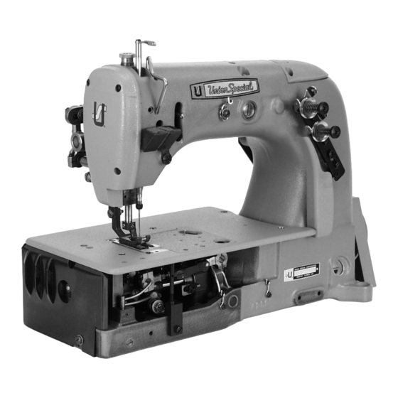
- Page 1 STYLES ADJUSTING INSTRUCTIONS AND ILLUSTRATED PARTS LIST 53700B 53800B STREAMLINED FIFTY THOUSAND SERIES CATALOG NO. 100L SECOND EDITION 11/21/03...
- Page 2 MANUAL NO. 100L ADJUSTING INSTRUCTIONS AND LLUSTRATED PARTS LIST FOR 53700 /53800 SERIES MACHINES Second Edition Copyright 2003 Union Special Corporation Rights Reserved In All Countries Printed in U.S.A. Nov 2003 FOREWORD The new streamlined Class 53700 and 53800 machines bring to the automobile upholstery and seat cover industry new styling, improved lubrication, and light running high speed performance.
-
Page 3: Table Of Contents
CONTENTS IDENTIFICATION OF MACHINE ................................. 3 APPLICATION OF CATALOG ................................... 3 STYLES OF MACHINE ....................................3 NEEDLES ........................................4 ORDERING REPAIR PARTS ..................................4 ORDERING REPAIR PARTS (CONTINUED) ..............................5 IDENTIFYING PARTS ....................................5 USE GENUINE NEEDLES AND REPAIR PARTS ............................5 TERMS ........................................ -
Page 4: Identification Of Machine
080/032, 090/036, 100/040, 110/044, 125/049, 140/054, 150/060, 170/067. Also available for styles 53700B and 53800B is Type 143GS. It is a round shank, round point, No. 2 bag, double groove, spotted, chromium plated needle and is available in sizes 140/054, 150/060, 170/067. - Page 5 In those cases where a parts for the class 53700B and 53800B are not the same the difference will be shown in the illustrations and descriptions. When a part is used in all machines covered in this catalog no machine style is mentioned.
-
Page 6: Use Genuine Needles And Repair Parts
Excessive oil in the main reservoir may be drained at the plug screw in the main frame directly under the handwheel. The accompanying diagram also shows the threading of the single needle Class 53700B machine. Threading of the two needle Class 53800B machine is substantially the same. - Page 7 Fig. 1...
-
Page 8: Setting The Looper
SYNCHRONIZING LOOPER AND NEEDLE MOTIONS Check the synchronization of the looper and needle motions, using gauge No. T34 and plate No. 21227AD as follows: Insert the pin, which is included with the gauge, in the looper rocker for 2 needle machine use right looper. -
Page 9: Setting The Feed Dog
SETTING THE LOOPER (CONTINUED) The looper is set correctly front to back, as it moves to the left behind the needle, when its point passes as close as possible without contacting the needle (.001-.002). If adjustment is necessary, loosen screw (E, Fig. - Page 10 Fig.6), and move upper feed lift driving lever (A) so that the teeth of the upper feed dog is 5/32" (7.9mm) for style 53700B and 3/16" to 13/64" (4.8 to 5.2mm) for style Fig. 5 53800B, above the top of the throat plate.
-
Page 11: Changing Stitch Length
INITIAL SETTINGS OF UPPER RUNNING FEED MECHANISM (CONTINUED) Synchronizing the upper feed with the lower feed can be accomplished by loosening nut (A, Fig. 9) and moving the ball stud in the upper feed driving shaft segment lever (B). Retighten nut. CHANGING STITCH LENGTH Set the stitch to the required length. -
Page 12: Threading
THREAD TENSION RELEASE (CONTINUED) If adjustmentis needed, loosen tension release lever screw (A, Fig. 12), located at the back of the machine and move tension disc separator as required. Retighten screw. After adjustment there should be no binding at any point. SETTING HEIGHT OF PRESSER BAR The height of the presser bar (C, Fig. - Page 13 EXPLODED VIEWS DESCRIPTION OF PARTS...
- Page 15 Plug Screw ....................158B Frame Thread Eyelet for Style 53800B ............Screw ......................53780B Throat Plate Support Rod Bracket ..............Frame Thread Eyelet, for Style 53700B ............Screw ......................50-648BLK Lucite Oil Guage ................... 51291A Looper Thread Guard ................... Screw, for looper thread guard ..............
- Page 17 BUSHINGS, OIL TUBES, WICKS AND MISCELLANEOUS COVERS Ref. A m t . N o . Description Req. Part No. 22541B Screw ......................52882AD Crank Chamber Cover, upper ..............39582L Oil Cap ....................52882AC Oil Cap Torsion Spring ................50-789BLK Oil Cap Hinge Pin ..................52882AA Drip Plate ....................
- Page 19 BUSHINGS, OIL TUBES, WICKS AND MISCELLANEOUS COVERS CONTINUED Ref. A m t . Req. N o . Part No. Description 1. thru 35. See Previous page 660-136 Feed Crank Link Oil Tube ................258A Nut ......................52936 Feed Rocker Shaft Bushing ................51242S Looper Drive Lever Shaft Bushing, rear ............
-
Page 21: Looper Drive Eccentric Assembly
CRANKSHAFT AND UPPER FEED DRIVING ROCK SHAFT PARTS Ref. A m t . N o . Description Req. Part No. 51321G "V" Belt Handwheel ..................22894H Spot Screw, for round and "V" belt handwheel ........22894E Set Screw, for round and "V" belt handwheel ......... 22569B Screw, for housing .................. - Page 23 Looper Rocker Frame, for Style 53800B ............Spot Screw ....................Set Screw ..................... 52444B Looper Rocker Frame, for Stle 53700B ............52825D Looper Needle Guard Holder, for Style 53700B ..........33174B Screw ..................... Screw ..................... 51325 Looper Needle Guard, for Style 53700B ............
- Page 25 22729C Bearing Cap Screw ................50-458BLK Spring Pin ....................12538 Nut ....................... 53710 Looper Needle Guard, for 53700B older models .......... Screw ......................51409C Looper, for Style 53700B ................1740 Looper Needle Guard Pin ..............21211 Looper Collar, for Style 53700B ..............
- Page 27 Screw ..................... 41071G Nut ....................... 33174B Screw ......................52889A Presser Bar Bushing, upper and presser spring regulator ......53787 Presser Spring ....................22768 Scew ......................56358 Needle Bar Thread Eyelet, for Style 53700B ........... 35. thru 67. See Following page...
- Page 29 Screw ......................HA81 Screw ......................22768 Screw ......................56358A Needle Lever Thread Eyelet, for Style 53700B ..........51217 Needle Bar, for Style 53700B ................. Needle Clamp Nut, for Style 53700B ............. 53720 Presser Foot, for Style 53700B ................ Screw, for Style 53700B ................
- Page 31 UPPER FEED LIFT AND PRESSER FOOT LIFTER PARTS Ref. A m t . Req. N o . Part No. Description 53750 Needle Lever and Upper Feed Lift Driving Lever Shaft ......... 53754 Upper Running Feed Lift Driving Lever ............55235D Locking Stud ..................
- Page 33 THREAD TENSION PARTS FOR SINGLE NEEDLE MACHINE Ref. A m t . Req. N o . Part No. Description 43266 Tension Post Nut ................... 80557 Spacing Washer ..................52892 Tension Post Support ..................51192G Tension Post Thread Eyelet ................21657-3 Tension Disc Separator ................
- Page 35 A m t . Req. N o . Part No. Description 21101W4 Thread Stand, complete, for Style 53800B ........... 21101W2 Thread Stand, complete, for Style 53700B ........... 12288403 Tweezer ....................... 21201 Screw Driver ....................660-264 Hook ......................421D28 Treadle Chain ....................
- Page 36 NOTES...
- Page 37 NOTES...
-
Page 38: Numerical Index Of Parts
NUMERICAL INDEX OF PARTS Part No. Page No. Part No. Page No. Part No. Page No. Part No. Page No. 1 0 9 ....3 3 2 2 5 8 7 . - Page 39 NUMERICAL INDEX OF PARTS Part No. Page No. Part No. Page No. Part No. Page No. Part No. Page No. 5 2 8 4 9 ... . . 2 1 5 3 7 8 3 C .
- Page 40 Union Special Corporation Corporate Office One Union Special Plaza Huntley, IL 60142 Phone: 847•669•5101 Fax: 847•669•4454 Union Special GmbH JUKI CORPORATION EuropeanDistributionCenter INTERNATIONAL SALES DIVISION Raiffeisenstrasse 3 8-2-1, KOKURYO - CHO, D-71696 Möglingen, Germany CHOFU-SHI, TOKYO 182, JAPAN Tel: 49•07141•247•0 PHONE: 03(3430)4001~5 Fax: 49•07141•247•100 FAX: 03(3430)4909 .
Need help?
Do you have a question about the 53700B and is the answer not in the manual?
Questions and answers